

ProductPRODUCT
Featured products
Contact Us
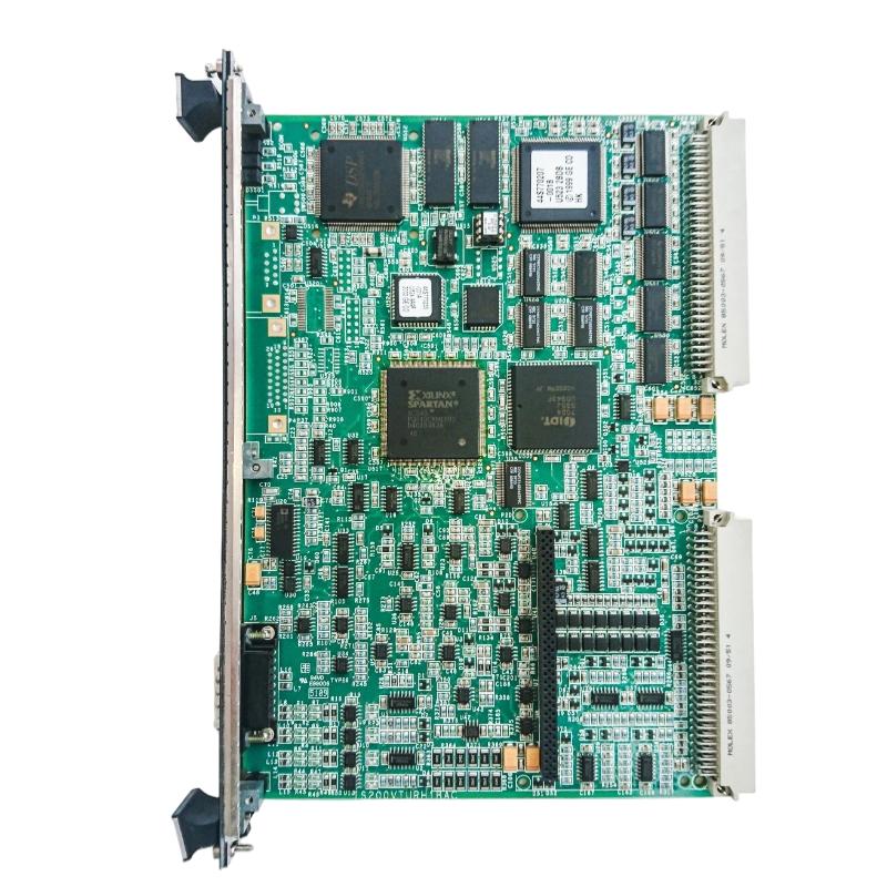
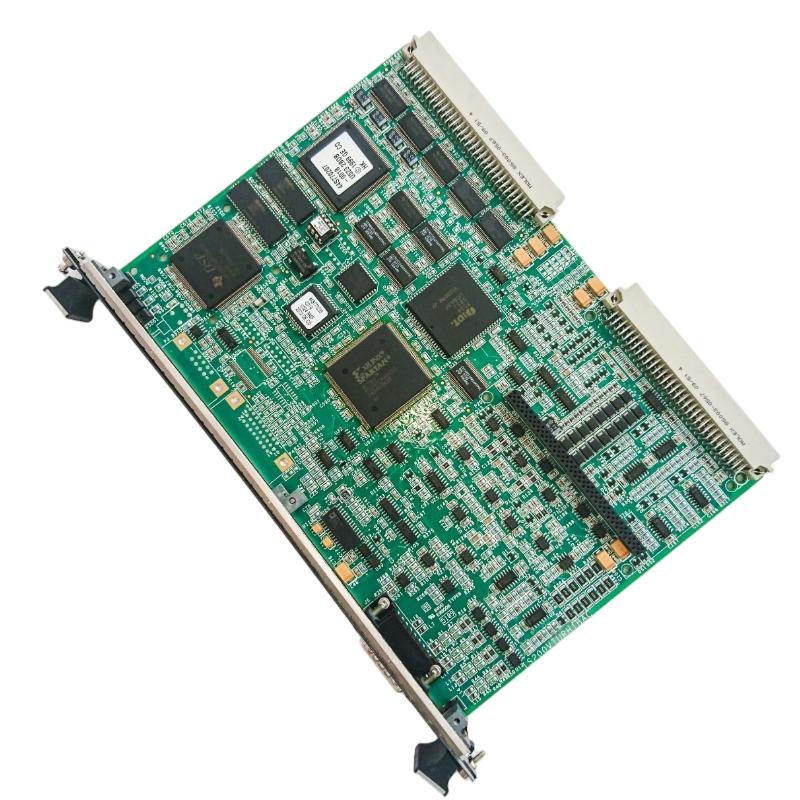
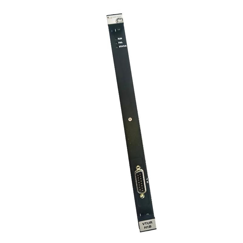
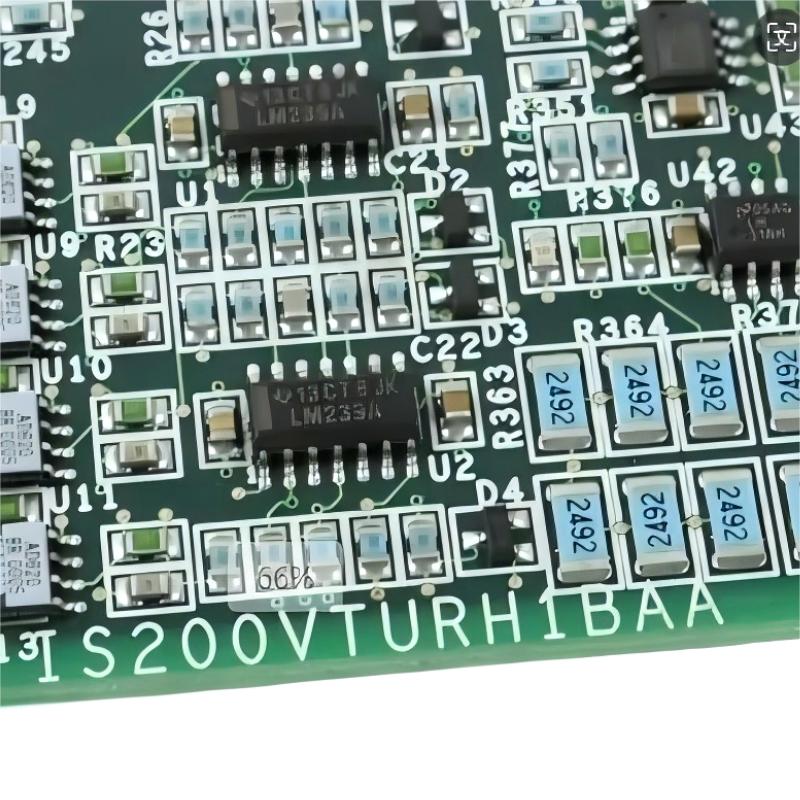
- GE
- IS200VTURH1BAA
- Turbine Protection Plate
- USA
- 210 x 180 x 60 mm
- 0.408 kg
- Xiamen, China
- New & In Stock
- T/T, PayPal, Western Union
- 1 Year
- 1-3 Working Days
- DHL, UPS, TNT, FedEx and EMS.
- 24-Hour Service
- COO
- 5
Our advantage

Global Logistics
We have a 10-year logistics and express cooperation agreement, so our products can be shipped to any place in the world.

Brand new and original
Our products are imported in bulk from the place of origin. Because of the cooperative relationship, our products are all original and 100% new.

24-hour service
We provide 7*24 hours service to our customers. We will be there whenever you need us.

Price advantage
All our products are priced very favorably because we have our own warehouse and supply.
| Company Information | |||
| [email protected] | |||
| Mobile | +8615980777398 | ||
| +8615980777398 | |||
| 15980777398 |
Product Overview
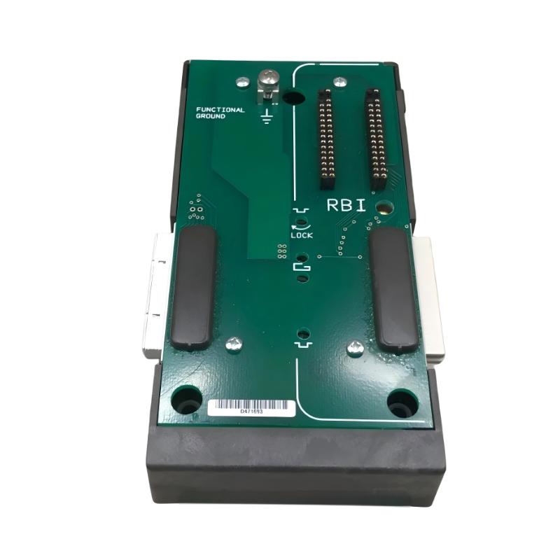
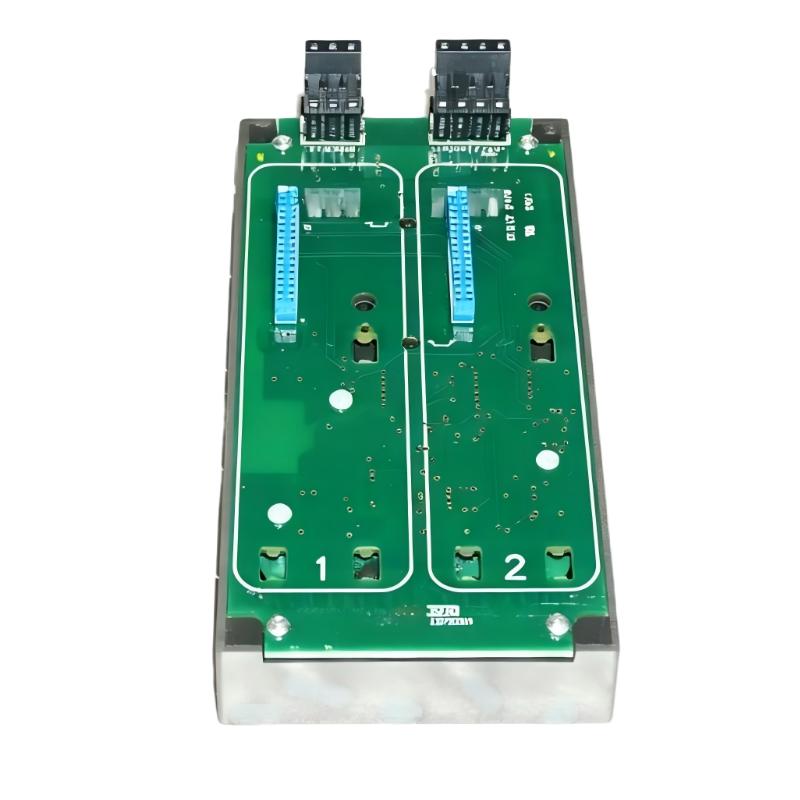
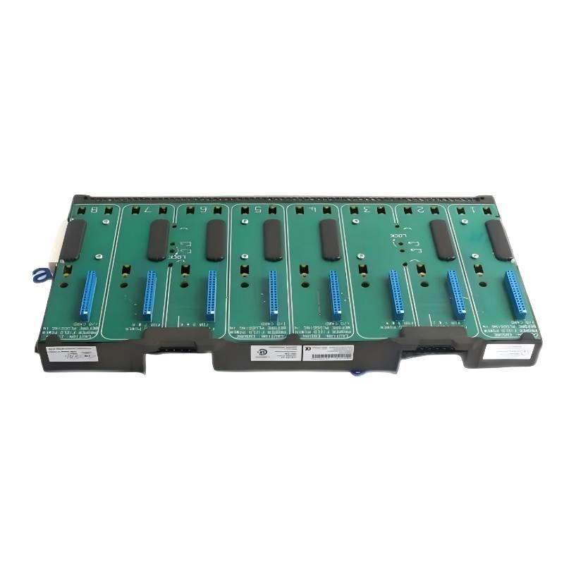
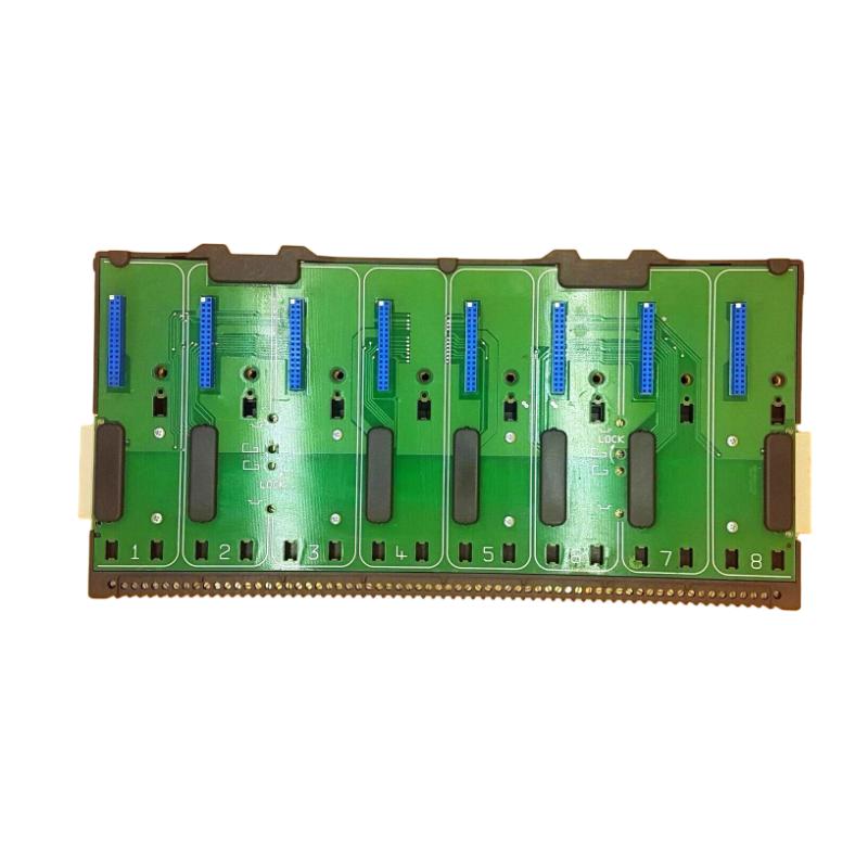
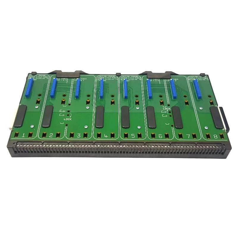
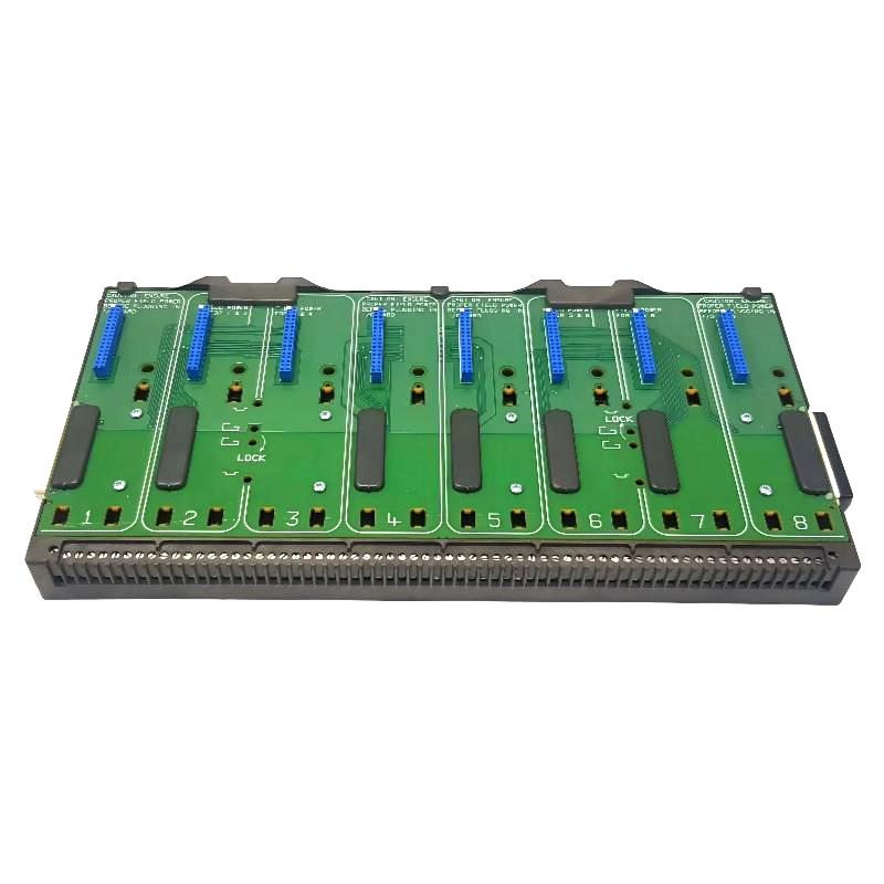
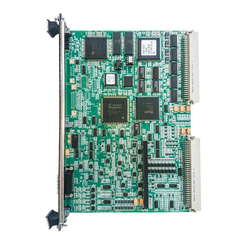
The GE IS200VTURH1BAA Turbine Protection Plate is an industrial control component associated with turbine protection and monitoring applications within compatible GE turbine control architectures. Turbine protection systems are designed to monitor critical operating conditions and help ensure that abnormal conditions can be detected and handled appropriately before they develop into more serious equipment problems.
In a turbine control system, protection-related hardware works together with sensors, terminal boards, I/O assemblies, control processors, and monitoring equipment. The protection interface provides an important connection between turbine operating information and the control logic responsible for monitoring system conditions.
The GE IS200VTURH1BAA has listed dimensions of 210 × 180 × 60 mm and a weight of approximately 0.408 kg. Its compact industrial construction allows it to be integrated into compatible turbine control equipment while maintaining a practical footprint for cabinet and system installation.
The exact electrical interfaces, signal assignments, protection logic, and system compatibility of the IS200VTURH1BAA depend on the host GE control system, associated hardware, and applicable board revision. For replacement applications, the complete model designation should therefore be verified before installation.
Technical Specifications
| Parameter | Specification |
|---|---|
| Manufacturer | General Electric (GE) |
| Model | IS200VTURH1BAA |
| Product Type | Turbine Protection Plate |
| Product Family | GE IS200 Series |
| Primary Function | Turbine protection and control-system interface |
| Application | Turbine Control and Protection |
| Installation | Compatible GE turbine control equipment |
| Dimensions | 210 × 180 × 60 mm |
| Weight | 0.408 kg |
| System Role | Turbine protection / monitoring interface |
| Typical Application | Industrial turbine control systems |
The exact electrical specifications, connector configuration, signal assignments, and compatibility should be verified against the applicable GE system documentation and hardware revision.
What Is the GE IS200VTURH1BAA?
The GE IS200VTURH1BAA is identified as a Turbine Protection Plate used in compatible GE turbine control and protection environments.
Turbines operate under demanding mechanical, electrical, thermal, and process conditions. Protection systems therefore need to monitor important operating parameters and provide reliable information to the control architecture.
A turbine protection system can be represented at a high level as:
Turbine Sensors → Protection Interface → Control Logic → Protection Response → Operator / Monitoring System
The IS200VTURH1BAA forms part of this broader protection architecture.
Rather than operating as an independent turbine controller, the protection plate works with other control-system components to support turbine monitoring and protection functions.
Turbine Protection Function
Turbine protection is an essential part of industrial turbine automation.
A turbine may be exposed to abnormal conditions involving:
- Speed
- Temperature
- Vibration
- Pressure
- Mechanical operating conditions
- Electrical conditions
- Lubrication
- Process conditions
The actual parameters monitored depend on the turbine type and control-system design.
Protection hardware provides a structured path for relevant operating information to reach the control and protection logic.
When abnormal conditions are identified, the control architecture can generate alarms, initiate protective actions, or place the equipment into an appropriate safe operating state according to the configured system strategy.
Function and Working Principle
Turbine Signal Interface
The protection system receives information from turbine-related sensors and associated field equipment.
The protection interface contributes to the transfer and organization of this information within the turbine control architecture.
Protection Monitoring
The control system can evaluate incoming information against configured operating conditions.
If a parameter moves outside an acceptable operating range, the system can generate an appropriate diagnostic or protection response.
Control-System Communication
Protection information can be transferred to associated control processors and monitoring equipment.
This allows turbine operating conditions to be monitored by operators and maintenance personnel.
Protective Response
The overall turbine control system determines the appropriate response to abnormal conditions.
Depending on the application, protection logic may be associated with alarm generation, controlled intervention, or turbine shutdown functions.
The exact protection strategy depends on the host system and should not be inferred solely from the board model.
Role in GE Turbine Control Systems
The IS200VTURH1BAA can be viewed as part of a larger turbine control and protection architecture.
A simplified structure is:
Turbine
↓
Sensors and Field Devices
↓
Protection Interface
↓
GE Control / I/O Architecture
↓
Protection and Control Logic
↓
Operator Interface / Monitoring System
Each layer contributes to turbine availability and operational safety.
Field sensors provide information about turbine conditions, interface equipment transfers the information into the control architecture, and control logic evaluates operating conditions.
The operator system provides visualization, diagnostics, alarms, and maintenance information.
Industrial Applications
The GE IS200VTURH1BAA is intended for applications associated with compatible turbine control systems.
Gas Turbine Systems
Gas turbines require continuous monitoring of operating conditions to maintain stable and controlled operation.
Protection-related control hardware can support the monitoring architecture associated with these systems.
Steam Turbines
Steam turbines contain multiple mechanical and process variables that require monitoring during operation.
Protection hardware can form part of the control architecture used to supervise these conditions.
Power Generation
Turbine control and protection systems are widely used in power-generation facilities.
Protection equipment contributes to the overall automation infrastructure used to monitor generating equipment.
Industrial Turbine Applications
Industrial facilities may use turbines for mechanical drive applications, power generation, or process-related equipment.
A compatible GE turbine control architecture can incorporate protection interface equipment as part of its monitoring and protection strategy.
System Integration
The IS200VTURH1BAA should be integrated according to the requirements of the complete GE turbine control system.
Important integration considerations include:
- Turbine control architecture
- Associated sensors
- Field wiring
- Terminal equipment
- I/O assemblies
- Control processors
- Protection logic
- Operator monitoring
- Hardware revision
- Cabinet configuration
The exact role of the protection plate depends on the system in which it is installed.
When replacing an existing unit, technicians should document the original configuration before removing the old component.
Installation Guidelines
Verify Product Identification
Before installation, confirm the complete part identification:
GE IS200VTURH1BAA
Check:
- Full model number
- Revision designation
- Board markings
- Connector configuration
- Installation position
- Associated control equipment
- Existing wiring
Because GE IS200-series components can have similar physical characteristics, the complete identification should always be used for compatibility verification.
Cabinet Installation
The listed dimensions of the IS200VTURH1BAA are:
210 × 180 × 60 mm
The cabinet should provide adequate clearance for:
- Mounting
- Cable routing
- Connector access
- Inspection
- Maintenance
- Appropriate ventilation
Wiring Verification
All associated wiring should be checked against the applicable system documentation.
Before commissioning, verify:
- Connector seating
- Cable identification
- Signal routing
- Grounding
- Shielding
- Terminal connections
Incorrect wiring can result in missing signals, incorrect diagnostic information, or unexpected protection-system behavior.
Commissioning Procedure
Turbine protection equipment should be commissioned carefully because it forms part of a critical control architecture.
Step 1: Confirm the Replacement Unit
Verify the model and revision before installation.
Step 2: Inspect the Hardware
Check the unit for physical damage, contamination, damaged connectors, or other visible problems.
Step 3: Verify Connections
Confirm all associated cables and connectors are correctly installed.
Step 4: Check the Control Architecture
Verify that associated I/O and control equipment are correctly configured.
Step 5: Apply Power
Restore system power according to the applicable turbine control procedures.
Step 6: Check Diagnostics
Review available system diagnostics for hardware, communication, or signal abnormalities.
Step 7: Verify Input Information
Confirm that relevant turbine operating information is being correctly received by the control architecture.
Step 8: Perform Functional Testing
Protection functions should be tested using approved plant procedures and appropriate test equipment.
Step 9: Document the Results
Record the installed hardware, revision, test results, and system status.
Troubleshooting Guide
Turbine Protection Signal Missing
If a turbine protection-related signal is missing, inspect the complete signal path.
Check:
- Field sensor
- Sensor wiring
- Terminal connections
- IS200VTURH1BAA connections
- Associated I/O equipment
- Control processor
- System configuration
- Diagnostic information
A failed sensor or damaged cable can create symptoms that appear to be an interface-board problem.
Incorrect Protection Information
If the control system displays incorrect information, verify:
- Field sensor condition
- Sensor wiring
- Terminal connections
- Interface hardware
- Associated I/O
- Control-system configuration
- Diagnostic status
The complete measurement path should be checked before replacing the protection component.
Intermittent Signals
Intermittent behavior may be caused by:
- Loose connectors
- Damaged cables
- Vibration
- Electrical interference
- Poor grounding
- Temperature-related conditions
- Sensor degradation
- Hardware faults
Physical inspection and diagnostic monitoring should be performed together.
Unexpected Protection Alarm
An unexpected alarm should not automatically be attributed to the IS200VTURH1BAA.
The investigation should include:
- Actual turbine operating conditions
- Sensor status
- Wiring
- Terminal equipment
- Interface hardware
- Controller diagnostics
- Configured protection logic
Protection alarms should always be investigated according to the plant’s approved turbine safety and maintenance procedures.
Preventive Maintenance
Inspect Connections
Periodically inspect connectors and associated wiring for looseness, damage, contamination, or signs of deterioration.
Inspect Cabinet Conditions
Maintain suitable cabinet conditions and protect electronic equipment from excessive dust, moisture, heat, and vibration.
Monitor Diagnostic Information
Control-system diagnostics can provide useful information about abnormal signals and hardware conditions.
Maintain Accurate Documentation
Record:
- Model number
- Revision
- Installation location
- Associated equipment
- Wiring information
- Maintenance history
Accurate documentation simplifies future troubleshooting and replacement.
Review Turbine Protection Performance
Protection-system testing should be performed according to the applicable plant maintenance schedule and safety procedures.
Physical Dimensions and Weight
The GE IS200VTURH1BAA has the following listed physical specifications:
Dimensions: 210 × 180 × 60 mm
Weight: 0.408 kg
These specifications are useful for:
- Cabinet planning
- Spare-parts management
- Replacement preparation
- Transportation
- Equipment identification
The physical envelope should be considered together with connector and wiring clearance during installation.
Replacement Considerations
When replacing a GE IS200VTURH1BAA Turbine Protection Plate, the complete model designation should be verified.
Important checks include:
- Full part number
- Revision designation
- Board markings
- Connector configuration
- Associated turbine-control equipment
- Existing wiring
- Cabinet location
- System configuration
A physically similar IS200-series board should not be assumed to be electrically or functionally interchangeable.
The replacement unit should be matched to the existing turbine control architecture before installation.
Related GE Turbine Control Components
A turbine protection installation may include several categories of associated equipment.
| Component Category | Typical Function |
|---|---|
| Turbine Protection Plate | Provides protection-system interface functionality |
| Turbine Sensor | Measures turbine operating conditions |
| Terminal Board | Organizes field wiring |
| I/O Board | Processes field signals |
| Control Processor | Executes control and protection logic |
| Communication Interface | Transfers system information |
| Operator Interface | Displays alarms and operating information |
| Turbine Actuator | Performs the required control action |
The exact components used with the IS200VTURH1BAA depend on the specific GE turbine control system.
Engineering Best Practices
Turbine protection systems require careful engineering and maintenance practices.
Recommended practices include:
- Verify all board identification before replacement.
- Maintain accurate turbine control drawings.
- Clearly identify sensor and field wiring.
- Inspect connectors during maintenance.
- Maintain appropriate grounding and shielding.
- Keep control cabinets clean and dry.
- Record hardware revisions.
- Use approved procedures for protection-system testing.
- Review diagnostic information after hardware replacement.
- Perform functional verification before returning equipment to normal operation.
These practices help improve the maintainability and reliability of turbine control and protection systems.
Key Advantages
Dedicated Turbine Protection Application
The IS200VTURH1BAA is identified as a turbine protection component for compatible GE control architectures.
Compact Industrial Construction
With listed dimensions of 210 × 180 × 60 mm, the unit provides a practical form factor for industrial control equipment.
Integration with Turbine Control Architecture
The protection plate can form part of a broader turbine monitoring and protection system.
Supports System-Level Monitoring
Protection-related information can be incorporated into the wider control and diagnostic architecture.
Suitable for Industrial Turbine Systems
The component is intended for integration into compatible industrial turbine control environments.
Technical FAQs
What is the GE IS200VTURH1BAA?
The GE IS200VTURH1BAA is identified as a Turbine Protection Plate used within compatible GE turbine control and protection systems.
What is the main function of the IS200VTURH1BAA?
Its role is associated with turbine protection and the integration of protection-related information into the turbine control architecture.
What are the dimensions of the IS200VTURH1BAA?
The listed dimensions are 210 × 180 × 60 mm.
How much does the IS200VTURH1BAA weigh?
The listed weight is approximately 0.408 kg.
Is the IS200VTURH1BAA a PLC?
No. It is identified as a turbine protection component rather than a general-purpose PLC controller.
Where is the IS200VTURH1BAA used?
It is intended for compatible GE turbine control and protection applications, including industrial turbine and power-generation environments.
What should be checked before replacing the board?
Technicians should verify the full model number, revision, connector configuration, wiring, associated control equipment, and host-system requirements.
Can another GE IS200 board replace the IS200VTURH1BAA?
A different IS200-series board should not be assumed to be interchangeable. Functional and electrical compatibility must be verified against the target turbine control system.
What can cause turbine protection signal problems?
Potential causes include sensor faults, damaged wiring, loose connectors, interface problems, I/O issues, configuration errors, electrical interference, or hardware failure.
Conclusion
The GE IS200VTURH1BAA Turbine Protection Plate is a specialized industrial control component associated with turbine monitoring and protection architectures. It provides an interface layer within compatible GE turbine control systems, allowing protection-related information to participate in the overall monitoring, diagnostic, and control process.
With listed dimensions of 210 × 180 × 60 mm and a weight of 0.408 kg, the IS200VTURH1BAA offers a compact form factor suitable for industrial turbine control equipment.
For installation and replacement applications, the complete GE IS200VTURH1BAA identification should be verified carefully. Correct wiring, connector inspection, system configuration, approved protection testing, and complete functional verification are essential when working with turbine protection equipment.