
NewsNEWCENTER
Featured products
Contact Us
GE IS200EHPAG1DAB Exciter High Voltage Pulse Amplifier Troubleshooting Guide
2026-09-16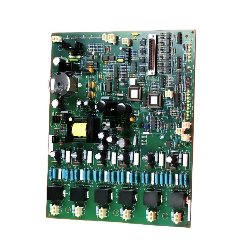
Table of Contents
- GE IS200EHPAG1DAB Fault Diagnosis Overview
- GE IS200EHPAG1DAB Common Fault Symptoms
- Common Causes of GE IS200EHPAG1DAB Faults
- GE IS200EHPAG1DAB Troubleshooting Diagnostic Logic
- GE IS200EHPAG1DAB Signal Testing and Fault Analysis
- GE IS200EHPAG1DAB Repair and Replacement Procedure
- GE IS200EHPAG1DAB Field Troubleshooting Case
- GE IS200EHPAG1DAB Troubleshooting FAQ
- GE IS200EHPAG1DAB Technical Summary
GE IS200EHPAG1DAB Fault Diagnosis Overview
The IS200EHPAG1DAB is used in an excitation-system pulse-amplification path, so troubleshooting must consider both electronic circuitry and the surrounding excitation architecture. A missing or abnormal excitation response can result from an input command problem, connector issue, grounding problem, board failure, or downstream power-stage condition.
A useful maintenance principle is to avoid starting with the assumption that the most visible component is defective. First determine where the expected signal disappears.
Control Command
      |
      v
Input Interface
      |
      v
IS200EHPAG1DAB
      |
      v
Pulse Output Path
      |
      v
Excitation Power Circuit
      |
      v
Generator Field Response
GE IS200EHPAG1DAB Common Fault Symptoms
Typical field symptoms associated with a problem in or around the pulse amplification path may include:
- Excitation does not respond as expected during startup.
- Generator excitation response becomes intermittent.
- Pulse-related diagnostics indicate an abnormal condition.
- The control system generates an excitation-related fault.
- Excitation behavior changes after cabinet maintenance.
- The system operates normally at one condition but becomes unstable during a more demanding operating state.
- A replacement board appears operational but the original symptom remains.
- Communication or control diagnostics occur together with excitation abnormalities.
These symptoms are not proof of an IS200EHPAG1DAB internal failure. The surrounding wiring and excitation equipment must be investigated before reaching that conclusion.
Common Causes of GE IS200EHPAG1DAB Faults
Incorrect or Missing Input Command
If the pulse command does not arrive correctly at the amplifier input, the downstream circuit may appear to have an amplifier fault even though the board is receiving no valid command.
Connector or Wiring Problems
Loose connectors, damaged conductors, contamination, or incorrectly reinstalled cables can interrupt pulse signals. This is particularly important after cabinet maintenance or board replacement.
Grounding and Electrical Noise
Improper grounding or shielding can introduce unwanted electrical interference into sensitive control signals. Excitation cabinets should be inspected according to the site’s grounding and EMC design.
Downstream Circuit Problems
A fault in the receiving power stage can produce abnormal feedback or loading conditions that may initially resemble a pulse-amplifier problem.
Internal Board Failure
If the input command is verified, the board interfaces are correct, the wiring is sound, and the downstream system is known to be healthy, the IS200EHPAG1DAB itself becomes a stronger candidate for further inspection or replacement.
GE IS200EHPAG1DAB Troubleshooting Diagnostic Logic
A disciplined troubleshooting sequence prevents unnecessary board replacement.
Reported Excitation Fault
          |
          v
Check System Alarm / Diagnostic Data
          |
          v
Verify Input Command
          |
     +----+----+
     |         |
   Valid     Missing
     |         |
     v         v
Check Board   Trace Control
Interface     Command Path
     |
     v
Check Pulse Output Path
     |
     v
Check Downstream Circuit
     |
     v
Compare Feedback
     |
     v
Determine Root Cause
If the control command is missing, troubleshoot upstream control logic first. If the command is present but the expected amplified pulse path is absent, investigate the board and its interfaces. If the pulse path appears correct but the excitation response remains abnormal, investigate the downstream circuit.
GE IS200EHPAG1DAB Signal Testing and Fault Analysis
Testing should be performed using equipment and procedures appropriate for the excitation system. Because the IS200EHPAG1DAB is associated with high-voltage pulse circuitry, technicians should not probe energized high-energy interfaces without the correct qualifications, instruments, isolation, and approved procedure.
Recommended Diagnostic Sequence
- Record the exact system alarm or observed symptom.
- Check whether the fault is repeatable.
- Review recent maintenance activity.
- Verify the control command entering the relevant interface.
- Inspect the IS200EHPAG1DAB connectors.
- Check cable continuity where appropriate and safe.
- Verify grounding and shielding arrangements.
- Check the downstream receiving circuit.
- Compare feedback behavior with known-good commissioning records.
- Only then determine whether board replacement is justified.
Example Diagnostic Record
Initial condition:
Excitation command present
Control processor operating normally

Observed condition:
Expected downstream response not obtained

Inspection:
Board connector = mechanically secure after correction
Control cable = continuity verified
Grounding = checked
Downstream circuit = requires further verification

Diagnostic direction:
Do not condemn the pulse amplifier until the complete
signal path has been verified.
The values and conditions above are an illustrative field-diagnostic example, not a universal test specification for the GE IS200EHPAG1DAB.
GE IS200EHPAG1DAB Repair and Replacement Procedure
When troubleshooting indicates that the board may be defective, repair or replacement should be performed using a controlled maintenance procedure.
Step 1: Confirm the Fault
Document the symptom, alarm information, operating condition, and any diagnostic evidence before removing the board.
Step 2: Isolate the Equipment
Apply the site’s approved lockout, isolation, and stored-energy procedures. Do not begin board removal until the equipment is confirmed safe for maintenance.
Step 3: Inspect the Existing Board
Look for visible contamination, damaged connectors, abnormal discoloration, mechanical damage, or other signs that may help explain the failure.
Step 4: Verify the Replacement
Confirm the complete GE IS200EHPAG1DAB identification and applicable revision before installation. A board that looks similar should not be substituted without compatibility verification.
Step 5: Reinstall and Test
Reconnect the wiring according to the approved system documentation. Perform preliminary checks before returning the excitation system to controlled operation.
Step 6: Reproduce the Original Operating Condition
A repair should not be considered complete simply because the controller starts. Recreate the condition under which the original fault occurred and verify stable excitation response.
GE IS200EHPAG1DAB Field Troubleshooting Case
During a representative maintenance investigation on a generator excitation cabinet, the operator reported that the excitation response became abnormal during a controlled operating transition. Initial inspection showed no obvious physical damage to the IS200EHPAG1DAB.
The maintenance team first checked the controller status and confirmed that the command-generation section was operating. They then inspected the pulse interface and discovered that one connector had not been fully seated following previous cabinet maintenance.
After correcting the connector, the signal path was retested. The excitation response returned to normal behavior during the same operating transition that had previously produced the fault.
This type of case demonstrates why troubleshooting should progress from input command to board interface and then to downstream response. Replacing an expensive control board without checking the connector path can leave the original fault unresolved.
GE IS200EHPAG1DAB Troubleshooting FAQ
How can I determine whether the IS200EHPAG1DAB is actually defective?
Verify the input command, connector condition, wiring, grounding, output path, and downstream circuit first. A board becomes a stronger suspect when the surrounding interfaces have been verified and the expected board function is still absent.
Why can a loose connector create an apparent pulse-amplifier failure?
A loose connector can interrupt or distort the signal path. The controller may continue operating while the downstream excitation circuit fails to receive the expected command, making the amplifier appear to be the source of the problem.
Should I replace the board if the excitation system reports a fault?
Not automatically. Alarm information should be combined with signal measurements, connector inspection, wiring checks, and downstream circuit verification before deciding that the board requires replacement.
What should be checked after replacing the GE IS200EHPAG1DAB?
Verify connector installation, control-system diagnostics, command transmission, pulse-path behavior, relevant feedback signals, and the original operating condition that caused the fault. Record the final test results for future maintenance.
Can high-voltage pulse signals be checked with ordinary test equipment?
Testing high-energy pulse circuits requires instruments, probes, isolation methods, and procedures suitable for the actual excitation system. Technicians should follow the equipment-specific safety and measurement requirements rather than improvising a test method.
GE IS200EHPAG1DAB Technical Summary
Effective GE IS200EHPAG1DAB fault diagnosis requires a system-level approach. The board operates within a larger excitation architecture, so abnormal generator-field behavior cannot be attributed to the pulse amplifier without checking the command source, connectors, wiring, grounding, downstream power circuit, and feedback signals.
The most practical troubleshooting strategy is to identify where the expected signal path changes from normal to abnormal. By separating upstream control, IS200EHPAG1DAB pulse amplification, and downstream excitation response, maintenance engineers can reduce unnecessary board replacement and establish a more defensible root-cause diagnosis.