
NewsNEWCENTER
Featured products
Contact Us
GE IS200EHPAG1DAB Exciter High Voltage Pulse Amplifier Installation Guide
2026-09-16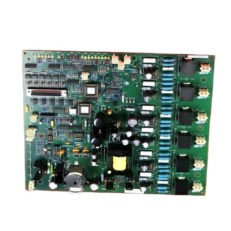
Table of Contents
- GE IS200EHPAG1DAB Installation Overview
- GE IS200EHPAG1DAB Function in Excitation Systems
- GE IS200EHPAG1DAB Installation Preparation
- GE IS200EHPAG1DAB Mounting and Cabinet Layout
- GE IS200EHPAG1DAB Wiring and Signal Setup
- GE IS200EHPAG1DAB Setup and Commissioning
- GE IS200EHPAG1DAB Installation Validation
- GE IS200EHPAG1DAB Field Commissioning Case
- GE IS200EHPAG1DAB Installation FAQ
- GE IS200EHPAG1DAB Technical Summary
GE IS200EHPAG1DAB Installation Overview
The IS200EHPAG1DAB is associated with excitation-system pulse amplification and is intended for use where controlled pulse signals must be processed or amplified within an industrial excitation architecture. Because excitation equipment can involve high-energy electrical circuits, installation should always follow the actual system drawings, approved wiring documentation, isolation procedures, and site safety requirements.
Before installing the GE IS200EHPAG1DAB, technicians should identify the upstream control board, downstream power or firing circuit, associated feedback signals, and the cabinet protection arrangement. A board that appears mechanically compatible may still be electrically unsuitable if the connector assignments, system revision, or application configuration does not match.
GE IS200EHPAG1DAB Function in Excitation Systems
The primary purpose of a high-voltage pulse amplifier in an excitation system is to provide the required interface between low-level control pulses and the downstream switching or firing circuitry. In a complete excitation controller, pulse timing and command information may originate in a control or firing-control circuit, while the amplifier provides the appropriate signal drive for the next stage.
A simplified signal relationship can be represented as:
Excitation Controller
        |
        v
Pulse / Firing Command
        |
        v
GE IS200EHPAG1DAB
High Voltage Pulse Amplification
        |
        v
Excitation Power Stage
        |
        v
Generator Field Circuit
This means that installation quality can directly affect system behavior. Incorrect grounding, damaged connectors, signal interference, or an incorrect board revision may produce symptoms that initially appear to be failures in the power section.
GE IS200EHPAG1DAB Installation Preparation
A controlled preparation process reduces the possibility of commissioning errors. Before handling the board, technicians should review the equipment documentation and establish the exact electrical boundary of the work.
- Confirm the complete GE IS200EHPAG1DAB part number and board revision.
- Verify that the replacement board matches the intended excitation-system configuration.
- Record existing connector locations and cable identification.
- Review excitation cabinet drawings before disconnecting wiring.
- Apply the required electrical isolation and lockout procedures.
- Check for residual electrical energy before accessing the equipment.
- Inspect the cabinet for contamination, moisture, loose hardware, or overheating.
- Check the condition of mating connectors and wiring harnesses.
- Keep high-level pulse wiring separated from sensitive low-level signal wiring where the system design requires it.
For replacement work, photographs and connector labels can be useful, but they should not replace the approved wiring diagram. Field wiring may have been modified during previous maintenance activities.
GE IS200EHPAG1DAB Mounting and Cabinet Layout
The IS200EHPAG1DAB should be installed in the correct board position within the excitation cabinet. Mechanical installation should provide secure support without stressing the printed circuit board, connectors, or cable assemblies.
During installation, inspect the mounting area for dust, conductive contamination, loose metal particles, and evidence of excessive heat. Excitation cabinets can experience substantial electrical and thermal stress, so environmental condition is an important part of commissioning reliability.
Mechanical Installation Checklist
- Verify that the cabinet is electrically isolated.
- Inspect the board and connector interfaces before installation.
- Confirm the correct board position from the system documentation.
- Install the board without forcing any connector.
- Secure the board using the designated mounting hardware.
- Check that adjacent wiring does not interfere with the board or cooling path.
- Confirm that all connectors are fully seated.
GE IS200EHPAG1DAB Wiring and Signal Setup
Wiring is one of the most important parts of a GE IS200EHPAG1DAB installation. The exact connector and terminal assignments should be verified against the documentation for the specific excitation system. Technicians should not assume that a visually similar IS200 board uses identical signal assignments.
The practical wiring sequence is to identify the signal source, the amplifier interface, and the downstream receiving circuit before applying operating power.
Pulse Control Source
       |
       |  Control / Pulse Interface
       v
+----------------------+
| GE IS200EHPAG1DAB    |
| High Voltage Pulse   |
| Amplifier            |
+----------------------+
       |
       |  Amplified Pulse Interface
       v
Excitation Power Stage
       |
       v
Generator Field System
Wiring Inspection Points
- Check connector orientation before insertion.
- Inspect contacts for oxidation or mechanical damage.
- Verify cable identification against the electrical drawing.
- Check shield and grounding arrangements where applicable.
- Keep wiring away from unnecessary mechanical stress.
- Inspect for damaged insulation or loose conductors.
- Confirm that no signal cable has been accidentally moved to an adjacent connector.
Do not apply high-energy operating conditions simply to determine whether an uncertain connection is correct. When connector identification is unclear, resolve the wiring documentation first.
GE IS200EHPAG1DAB Setup and Commissioning
Commissioning should proceed from low-risk verification toward normal excitation operation. The objective is to determine whether the IS200EHPAG1DAB is correctly integrated before the generator is exposed to the full operating sequence.
Initial Power-Up
- Confirm that all required mechanical and electrical connections have been inspected.
- Verify cabinet isolation has been removed only when the system is ready for controlled energization.
- Check for abnormal indications during initial power application.
- Verify the upstream control system starts normally.
- Check that the excitation controller recognizes the expected hardware configuration.
- Monitor pulse-related feedback or diagnostic information provided by the control system.
- Proceed to functional testing only after the preliminary checks are satisfactory.
Commissioning Logic
Board Installed
      |
      v
Connector Inspection
      |
      v
Control System Power-Up
      |
      v
Check Diagnostics
      |
      v
Verify Pulse Command
      |
      v
Verify Amplified Pulse Path
      |
      v
Controlled Excitation Test
      |
      v
Record Operating Values
The exact test sequence depends on the generator and excitation architecture. High-voltage pulse circuits should only be tested by qualified personnel using the procedures established for that equipment.
GE IS200EHPAG1DAB Installation Validation
A successful installation should be validated at both the board level and the system level. Merely seeing the control cabinet power up does not prove that the pulse amplification path is functioning correctly.
- Confirm stable controller operation.
- Verify that no unexpected board or communication diagnostics are present.
- Confirm correct command transmission through the pulse-control path.
- Check relevant excitation feedback signals.
- Monitor the excitation system during controlled operation.
- Compare measured behavior with commissioning records.
- Check for abnormal heating, vibration, or electrical noise.
- Record the final board identification and maintenance information.
GE IS200EHPAG1DAB Field Commissioning Case
In one representative excitation-system commissioning case, a replacement pulse-amplifier board was installed after intermittent excitation-control behavior had been reported. The control processor started correctly after installation, but the commissioning team observed inconsistent pulse-related behavior during a controlled functional test.
Instead of immediately declaring the replacement board defective, the engineers divided the system into three sections: command generation, pulse amplification, and downstream power-stage response. Connector seating was checked first, followed by cable continuity and the grounding arrangement.
The investigation identified a poorly seated connector in the pulse interface path. After the connector was correctly secured, the command path became stable and the excitation response returned to the expected operating pattern. The example illustrates an important commissioning principle: a board-level symptom does not automatically mean that the circuit board itself has failed.
GE IS200EHPAG1DAB Installation FAQ
What should be checked before installing the GE IS200EHPAG1DAB?
Verify the complete part number, board revision, system compatibility, connector identification, cabinet condition, and approved wiring documentation. Electrical isolation and site safety procedures must also be completed before handling the board.
Can the connector positions be identified only from the physical appearance of the board?
No. Physical appearance should not be used as the sole method of connector identification. The applicable system drawings and board documentation should be used to confirm each interface.
Why is grounding important during IS200EHPAG1DAB installation?
Excitation systems can contain high-energy switching and pulse circuits that are sensitive to electrical noise and grounding problems. Correct grounding and shielding practices help maintain signal integrity and reduce unintended interference.
What should be done if the controller starts but the excitation response is abnormal?
Check the complete signal path rather than replacing the board immediately. Verify the control command, connector seating, cable continuity, grounding, downstream interface, and relevant feedback signals.
Should the IS200EHPAG1DAB be tested under full operating conditions immediately after installation?
No. Commissioning should use a controlled sequence appropriate to the excitation system. High-energy testing should be performed only by qualified personnel following the approved equipment procedure.
GE IS200EHPAG1DAB Technical Summary
The GE IS200EHPAG1DAB Exciter High Voltage Pulse Amplifier is an important interface component within an industrial excitation architecture. A reliable installation requires more than correct mechanical placement: technicians must verify board identity, connectors, pulse interfaces, grounding, cabinet condition, and downstream system response.
For installation and commissioning, the most effective approach is to work systematically from the control command toward the excitation power stage. When abnormal behavior occurs, separating the system into command, amplification, and downstream sections provides a practical method for identifying the actual fault location without unnecessarily replacing serviceable hardware.