

ProductPRODUCT
Featured products
Contact Us
- Woodward
- 8516-038
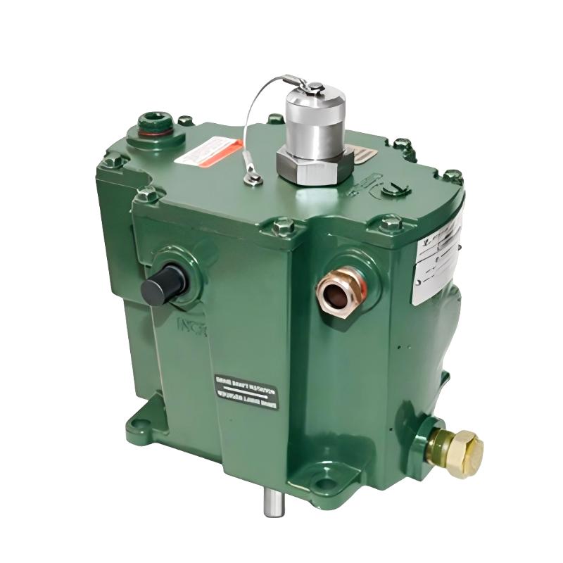
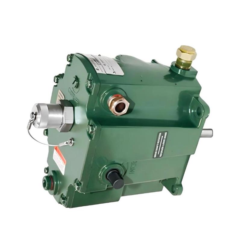
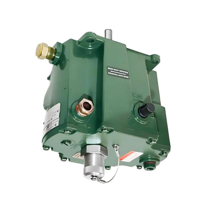
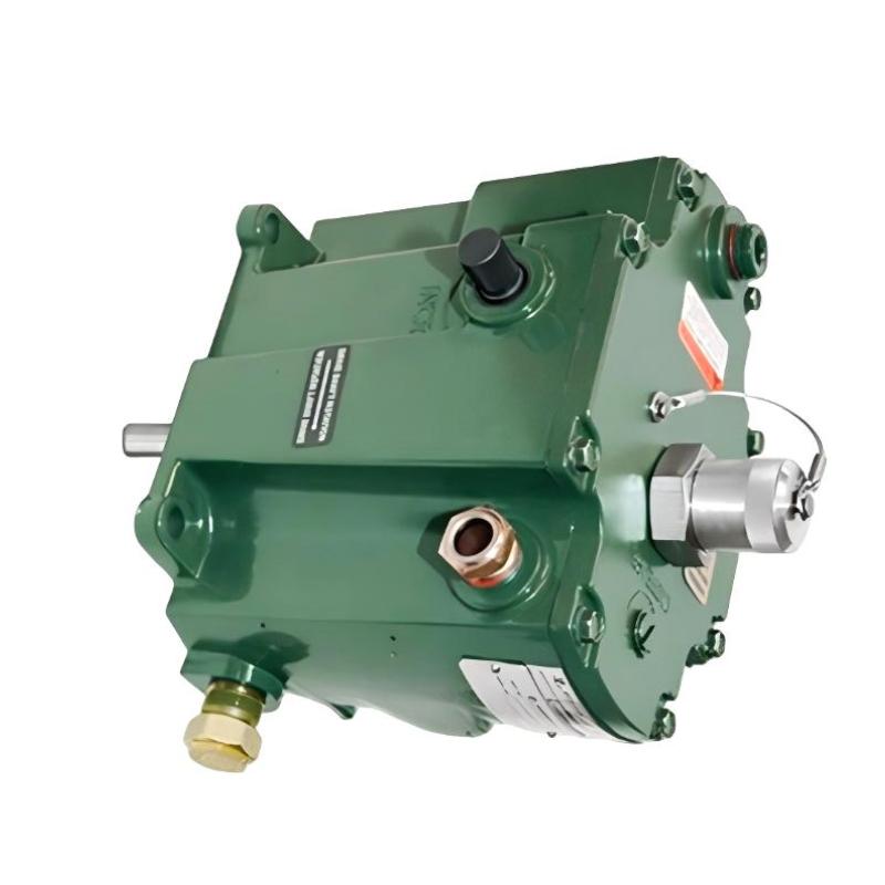
- Mechanical Hydraulic Governor
- USA
- 250 × 50 × 150 mm
- 2 kg
- Xiamen, China
- New & In Stock
- T/T, PayPal, Western Union
- 1 Year
- 1-3 Working Days
- DHL, UPS, TNT, FedEx and EMS.
- 24-Hour Service
- COO
- 8
Our advantage

Global Logistics
We have a 10-year logistics and express cooperation agreement, so our products can be shipped to any place in the world.

Brand new and original
Our products are imported in bulk from the place of origin. Because of the cooperative relationship, our products are all original and 100% new.

24-hour service
We provide 7*24 hours service to our customers. We will be there whenever you need us.

Price advantage
All our products are priced very favorably because we have our own warehouse and supply.
| Company Information | |||
| [email protected] | |||
| Mobile | +8615980777398 | ||
| +8615980777398 | |||
| 15980777398 |
Product Overview
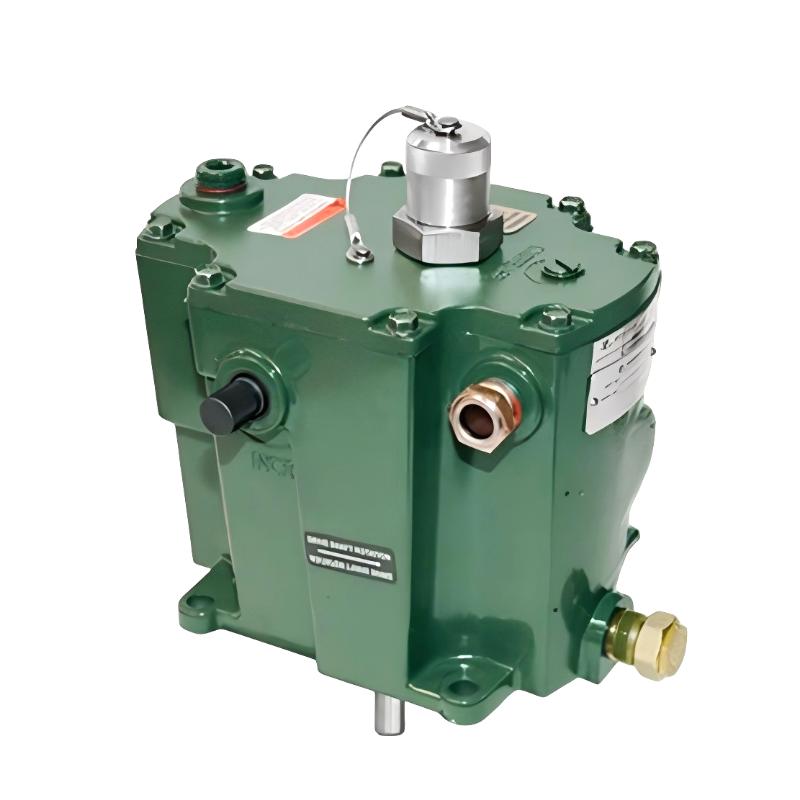
The Woodward 8516-038 is a TG-13 Series Mechanical Hydraulic Governor used for speed control on engines and other prime movers. It combines mechanical speed sensing with hydraulic control to regulate fuel or steam input according to changes in engine operating conditions.
In a typical engine installation, the governor is mechanically coupled to the engine or prime mover so that rotational speed can be continuously sensed. When load changes cause the engine speed to move away from the selected operating point, the governor responds through its internal mechanical and hydraulic control mechanism.
The governor is suited to applications where a self-contained mechanical-hydraulic speed control device is preferred over an electronic governor. It can be applied to industrial engines, generator sets, mechanical drive equipment, and other prime-mover systems requiring stable speed regulation.
The TG-13 Series is particularly relevant to engine systems where governor response must directly influence the fuel or actuator mechanism. Its mechanical feedback arrangement allows engine speed changes to produce corresponding control corrections without relying on a digital control processor for the primary speed-regulating function.
Technical Specifications
| Parameter | Specification |
|---|---|
| Model | 8516-038 |
| Product Family | TG-13 Series |
| Product Type | Mechanical Hydraulic Governor |
| Primary Function | Engine speed regulation |
| System Role | Prime-mover speed control |
| Control Method | Mechanical-hydraulic |
| Application | Engine, generator, and industrial prime-mover control |
| Dimensions | 250 × 50 × 150 mm |
| Weight | 2 kg |
Product Features
- TG-13 Series Mechanical Hydraulic Governor for prime-mover speed regulation.
- Combines mechanical speed sensing with hydraulic control.
- Responds directly to changes in engine rotational speed.
- Suitable for mechanical fuel or actuator control arrangements.
- Applicable to engine-driven generator and industrial mechanical-drive systems.
- Provides continuous speed-regulating action during changing load conditions.
- Suitable for applications where mechanical-hydraulic governor technology is required.
Working Principle
The governor senses prime-mover speed through its mechanical drive connection. As rotational speed changes, the internal flyweight mechanism responds to the change in centrifugal force and shifts the governor control mechanism.
The resulting mechanical movement controls hydraulic pressure within the governor. This hydraulic action moves the connected actuator or fuel-control mechanism, increasing or reducing energy input to the engine as required.
Engine Speed → Mechanical Speed Sensing → Governor Mechanism → Hydraulic Control → Fuel / Actuator Position → Engine Speed Correction
When engine load increases and speed begins to decrease, the governor reacts to the reduced speed condition and moves the control system toward greater fuel or energy input. When the load decreases and engine speed rises, the governor produces the opposite correction.
This closed mechanical-hydraulic feedback process continuously balances engine output against load demand and helps maintain the configured operating speed.
Role in an Engine and Generator Control Architecture
The 8516-038 acts directly within the prime-mover speed-control loop. Unlike an electronic supervisory controller, the mechanical-hydraulic governor performs the primary speed correction through its sensing mechanism, internal control elements, and hydraulic output.
Architecture chain
Engine / Prime Mover → Speed Sensing → 8516-038 Governor → Fuel / Actuator Mechanism → Engine Power Output
| System Element | Function |
|---|---|
| Engine / Prime Mover | Produces mechanical power |
| Mechanical Speed Drive | Transfers rotational speed to the governor |
| 8516-038 Governor | Detects speed changes and generates the regulating action |
| Hydraulic Control Mechanism | Converts governor movement into actuator force |
| Fuel / Actuator Mechanism | Adjusts engine energy input |
| Generator / Mechanical Load | Applies the operating load to the prime mover |
Industrial Applications
| Application | Typical Use |
|---|---|
| Generator Sets | Mechanical speed regulation of engine-driven generators |
| Industrial Engines | Control of engine speed under changing load |
| Power Generation | Prime-mover speed control for generating equipment |
| Mechanical Drives | Maintaining operating speed of engine-driven machinery |
| Pumping Equipment | Engine speed regulation for mechanical pump drives |
| Standby Power Systems | Speed control of mechanically governed generator engines |
Installation and Maintenance
- Confirm that the TG-13 governor is suitable for the intended engine and actuator arrangement.
- Verify the mechanical drive connection and governor mounting arrangement before installation.
- Check the governor drive direction and mechanical coupling according to the engine configuration.
- Ensure the actuator or fuel-control linkage moves freely throughout its required operating range.
- Inspect the linkage for excessive backlash, binding, or mechanical interference.
- Connect the governor to the engine fuel or actuator mechanism according to the approved control arrangement.
- Verify the required hydraulic and mechanical interfaces before commissioning.
- Start the prime mover under controlled conditions and observe governor response during speed changes.
- Check speed stability during both increasing and decreasing load conditions.
- Investigate hunting, sluggish response, or unstable speed behavior before placing the equipment into normal service.
- Inspect the governor and connected linkage during scheduled engine maintenance.
- After governor replacement or major linkage work, perform a complete speed-control and load-response test before returning the engine or generator to service.
Related Components
| Component | Function |
|---|---|
| Engine Fuel System | Supplies and regulates fuel to the prime mover |
| Governor Drive | Transfers engine rotation to the governor |
| Fuel Control Linkage | Connects governor output to the engine fuel mechanism |
| Hydraulic Actuator | Converts hydraulic control action into mechanical movement |
| Engine Control Rack | Regulates fuel or energy input to the engine |
| Generator | Converts mechanical power into electrical power |
| Speed Sensing Mechanism | Provides rotational-speed feedback |
| Prime Mover | Provides the mechanical power being regulated |
Recommended Related Models
| Model / Product Family | Product Type | Typical Application |
|---|---|---|
| Woodward TG-13 Series | Mechanical Hydraulic Governor | Engine speed regulation |
| Woodward TG Series Governors | Mechanical Hydraulic Governor | Industrial prime-mover control |
| Woodward Mechanical Governors | Speed Governor | Mechanical engine control |
| Woodward Hydraulic Governors | Hydraulic Governor | Fuel and actuator regulation |
| Woodward Engine Control Systems | Engine Control System | Engine operating control |
| Woodward Generator Control Systems | Generator Controller | Generator-set automation |
| Woodward Hydraulic Actuators | Hydraulic Actuator | Fuel and mechanical control |
| Woodward Speed Control Components | Speed Control Equipment | Prime-mover speed regulation |
Key Advantages
- Provides mechanical-hydraulic speed regulation for prime movers.
- Responds directly to engine speed changes through mechanical feedback.
- Suitable for generator and industrial engine applications.
- Can operate without relying on electronic processing for the primary speed-control loop.
- Interfaces directly with mechanical fuel and actuator systems.
- Well suited to engine installations requiring established hydraulic governor technology.
Technical FAQs
How does the governor respond when generator load suddenly increases?
A sudden increase in generator load tends to reduce prime-mover speed. The governor detects the speed reduction through its mechanical sensing mechanism and adjusts the hydraulic control output toward a higher fuel or energy command, allowing the engine to recover toward its regulated speed.
What can cause unstable engine speed when a mechanical governor is otherwise functional?
Unstable speed can result from incorrect linkage adjustment, excessive mechanical play, improper governor settings, actuator problems, or changes in the engine’s fuel response. The governor should therefore be evaluated together with the complete mechanical control linkage and fuel system.
Why is the mechanical drive connection critical for TG-13 operation?
The governor depends on the prime mover’s rotational speed as its feedback signal. An incorrect drive arrangement, excessive coupling play, or abnormal drive condition can distort the sensed speed and lead to incorrect fuel-control movement.
How should governor performance be evaluated after servicing?
The engine should be operated through controlled speed and load changes while observing speed recovery, stability, and actuator response. The test should confirm that the governor responds consistently to both increasing and decreasing load conditions before normal operation resumes.