

ProductPRODUCT
Featured products
Contact Us
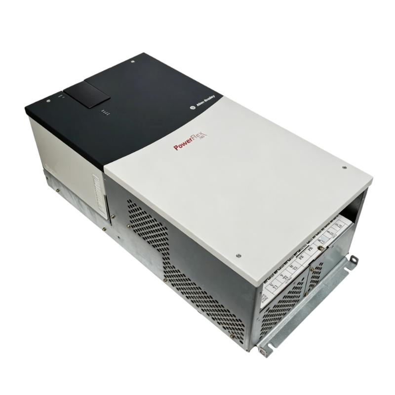
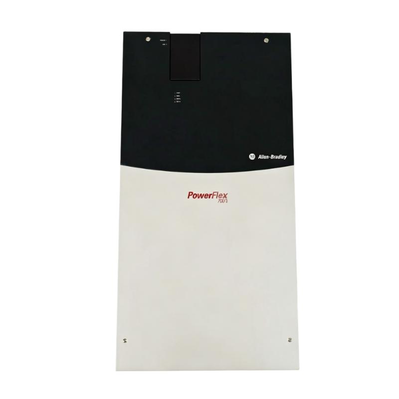
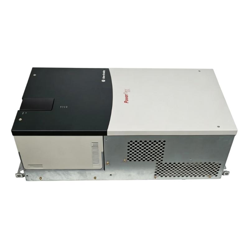
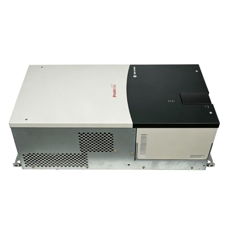
- Allen Bradley
- 20BP140A3ANNADC1
- PowerFlex 700 AC Drive
- USA
- 689.6 × 308.9 × 275.4 mm
- 37.19 kg
- Xiamen, China
- New & In Stock
- T/T, PayPal, Western Union
- 1 Year
- 1-3 Working Days
- DHL, UPS, TNT, FedEx and EMS.
- 24-Hour Service
- COO
- 70
Our advantage

Global Logistics
We have a 10-year logistics and express cooperation agreement, so our products can be shipped to any place in the world.

Brand new and original
Our products are imported in bulk from the place of origin. Because of the cooperative relationship, our products are all original and 100% new.

24-hour service
We provide 7*24 hours service to our customers. We will be there whenever you need us.

Price advantage
All our products are priced very favorably because we have our own warehouse and supply.
| Company Information | |||
| [email protected] | |||
| Mobile | +8615980777398 | ||
| +8615980777398 | |||
| 15980777398 |
Product Overview
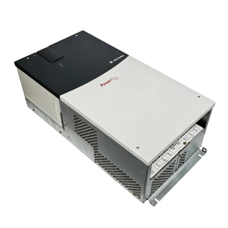
The Allen Bradley 20BP140A3ANNADC1 PowerFlex 700 AC Drive is an industrial AC drive used to regulate motor operation in automated machinery and process equipment. It serves as the power-control stage between the electrical distribution system and an AC motor, allowing the motor to operate according to commands generated by the automation system.
In a typical installation, the drive receives operating commands from a PLC, controller, HMI, or another control source. It then manages the motor-side electrical output so that the connected motor can respond to the required speed and operating conditions.
The 20BP140A3ANNADC1 belongs to the PowerFlex 700 family and is suitable for established industrial motor-control systems. It can be used where controlled motor operation is needed for conveyors, pumps, fans, material-handling equipment, and other rotating machinery.
For replacement applications, technicians should verify the complete catalog number and existing drive configuration. The motor, incoming power, control wiring, communication arrangement, and programmed parameters should all be reviewed before the replacement unit is placed back into service.
Technical Specifications
| Parameter | Specification |
|---|---|
| Manufacturer | Allen Bradley |
| Model | 20BP140A3ANNADC1 |
| Product Family | PowerFlex 700 |
| Product Type | AC Drive |
| Primary Function | Variable-Speed AC Motor Control |
| System Role | Motor Speed and Power Control |
| Application | Industrial Automation / Motor Control |
| Dimensions | 689.6 × 308.9 × 275.4 mm |
| Weight | 37.19 kg |
Product Features
The 20BP140A3ANNADC1 provides the electrical motor-control functions required within a PowerFlex 700 installation.
Key characteristics include:
- Allen Bradley PowerFlex 700 AC drive
- Model 20BP140A3ANNADC1
- Intended for industrial AC motor control
- Supports variable-speed motor operation
- Interfaces with PLC-based automation systems
- Suitable for machinery and process equipment
- Supports coordinated motor operation
- Provides drive status and diagnostic information
- Suitable for established PowerFlex 700 installations
- Useful for maintenance, replacement, and retrofit applications
The complete motor-control arrangement should be considered when selecting or replacing the drive. Electrical supply characteristics, motor requirements, mechanical load, and control architecture all affect application compatibility.
Working Principle
The 20BP140A3ANNADC1 regulates the electrical output delivered to an AC motor according to the required operating command.
A simplified power path is:
Incoming AC Supply → PowerFlex 700 → Controlled Motor Output → AC Motor → Mechanical Load
The operating sequence can be understood as follows:
-
Incoming Power
Electrical power enters the drive from the plant power system.
-
Internal Power Processing
The drive processes the incoming electrical energy through its power-conversion circuitry.
-
Command Reception
The required motor operation is established through the connected control architecture.
-
Output Regulation
The drive controls its motor output according to the operating command and configured control parameters.
-
Motor Operation
The AC motor converts the controlled electrical input into mechanical rotation.
-
Process Response
The motor drives the connected machine according to the required production or process condition.
-
Status Feedback
Drive operating status and diagnostic information can be used for monitoring and troubleshooting.
The complete control relationship can therefore be represented as:
Process Requirement → Control Command → PowerFlex 700 → AC Motor → Mechanical Process
Role in an Industrial Motor Control Architecture
The 20BP140A3ANNADC1 sits between the automation control layer and the motor power layer.
A practical system arrangement is:
PLC / Controller → Drive Command → PowerFlex 700 → AC Motor → Machine
The PLC or controller handles the process sequence, while the PowerFlex 700 translates the required operating condition into controlled motor operation.
This arrangement is particularly useful when motor speed needs to change with the process. A conveyor, for example, may require gradual acceleration during startup and a controlled running speed during production. A pump may similarly need to adjust its operating point as process demand changes.
For maintenance, the drive should be treated as one stage within the complete chain. If a motor does not respond correctly, checking the controller command, drive status, motor circuit, motor, and mechanical load in sequence can help isolate the actual source of the problem.
Industrial Applications
| Application | Typical Use |
|---|---|
| Conveyor Systems | Variable-speed material transportation |
| Pumping Equipment | Adjusting motor operation to process requirements |
| Industrial Fans | Regulating airflow through motor-speed control |
| Material Handling | Coordinating motor operation with production |
| Manufacturing Machinery | Controlling rotating machine equipment |
| Process Equipment | Matching motor operation to changing conditions |
| Production Lines | Coordinating motor-driven machinery |
| Industrial Mechanical Systems | Variable-speed AC motor control |
The actual application depends on the drive configuration, motor characteristics, mechanical load, and process requirements.
Installation and Maintenance
The PowerFlex 700 should be installed and maintained as part of the complete electrical and mechanical system.
Recommended practices include:
- Confirm the complete 20BP140A3ANNADC1 catalog number.
- Verify the replacement drive configuration.
- Record power and control connections before removal.
- Document relevant existing drive parameters.
- Isolate the incoming electrical supply before servicing.
- Follow appropriate electrical discharge procedures.
- Inspect incoming power connections.
- Check motor output terminals and cables.
- Verify grounding connections.
- Inspect cabinet ventilation and drive cooling paths.
- Check control and communication wiring.
- Verify motor-related configuration before startup.
- Test motor direction under controlled conditions.
- Check acceleration and deceleration behavior.
- Monitor diagnostic information during commissioning.
- Gradually return the machine to its normal operating load.
If the drive trips only under higher mechanical demand, inspect the motor, driven equipment, motor cable, operating parameters, and load conditions before replacing the drive again.
Related Components
| Component | Function |
|---|---|
| Allen Bradley PLC | Executes automation logic and generates commands |
| PowerFlex 700 AC Drive | Controls motor electrical output |
| AC Motor | Converts electrical energy into mechanical motion |
| Motor Cable | Transfers controlled power to the motor |
| Circuit Protection | Protects the drive power circuit |
| Disconnect Device | Provides electrical isolation |
| HMI | Provides operator control and monitoring |
| Communication Network | Transfers commands and status data |
| Mechanical Load | Receives motor torque |
| Grounding System | Supports electrical safety and system integrity |
Recommended Related Models
| Model / Product Family | Product Type | Typical Application |
|---|---|---|
| Allen Bradley 20BP140A3ANNADC1 | PowerFlex 700 AC Drive | Variable-speed AC motor control |
| Allen Bradley 20BP140A3ANNACC1 | PowerFlex 700 AC Drive | Industrial motor control |
| Allen Bradley 20BP105A3ANNACC1 | PowerFlex 700 AC Drive | Variable-speed motor applications |
| Allen Bradley PowerFlex 700 | AC Drive Family | Industrial motor control |
| Allen Bradley PowerFlex AC Drives | Variable Frequency Drive | Machine and process automation |
Key Advantages
- Allen Bradley PowerFlex 700 AC drive.
- Model 20BP140A3ANNADC1.
- Suitable for industrial AC motor control.
- Supports variable-speed motor operation.
- Provides the interface between automation commands and motor power.
- Suitable for machinery and process equipment.
- Supports drive-level monitoring and diagnostics.
- Integrates with established PowerFlex 700 architectures.
- Useful for maintenance, replacement, and retrofit projects.
Technical FAQs
How should the 20BP140A3ANNADC1 be integrated with a PLC-controlled machine?
The PLC or controller normally establishes the required motor operating command, while the PowerFlex 700 manages the motor-side electrical response. Control wiring, communication interfaces, and drive configuration should be verified as a complete system during commissioning.
What should be checked if the motor runs but does not reach the expected operating speed?
First compare the commanded speed with the drive’s actual operating condition. Then examine drive parameters, motor behavior, mechanical load, and any active diagnostic information. The issue may originate outside the drive itself.
Why is it useful to record the original drive configuration before replacement?
The replacement must reproduce the operating conditions required by the application. Recording relevant parameters, control connections, motor information, and communication settings helps prevent configuration-related problems during startup.
What symptoms suggest that a drive fault may actually originate from the connected machine?
Repeated trips that occur only during specific production conditions can indicate an external problem. Excessive mechanical load, a blocked pump, damaged bearings, or abnormal motor behavior can increase the demand placed on the drive and trigger protective functions.