

ProductPRODUCT
Featured products
Contact Us
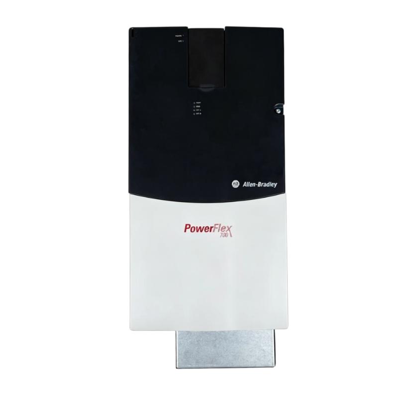
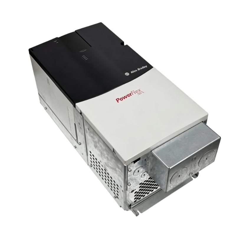
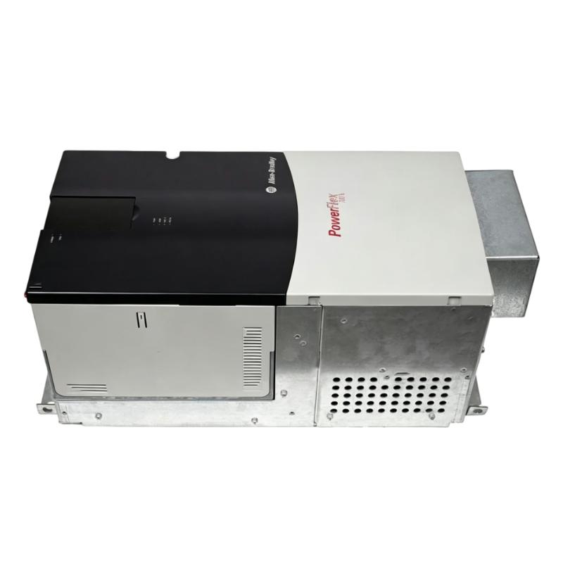
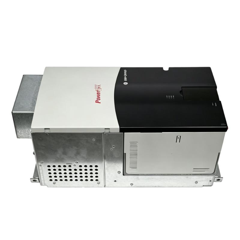
- Allen Bradley
- 20BF142A3ANNANC0
- PowerFlex 700 AC Drive
- USA
- 850 × 403.9 × 275.5 mm
- 71.44 kg
- Xiamen, China
- New & In Stock
- T/T, PayPal, Western Union
- 1 Year
- 1-3 Working Days
- DHL, UPS, TNT, FedEx and EMS.
- 24-Hour Service
- COO
- 42
Our advantage

Global Logistics
We have a 10-year logistics and express cooperation agreement, so our products can be shipped to any place in the world.

Brand new and original
Our products are imported in bulk from the place of origin. Because of the cooperative relationship, our products are all original and 100% new.

24-hour service
We provide 7*24 hours service to our customers. We will be there whenever you need us.

Price advantage
All our products are priced very favorably because we have our own warehouse and supply.
| Company Information | |||
| [email protected] | |||
| Mobile | +8615980777398 | ||
| +8615980777398 | |||
| 15980777398 |
Product Overview
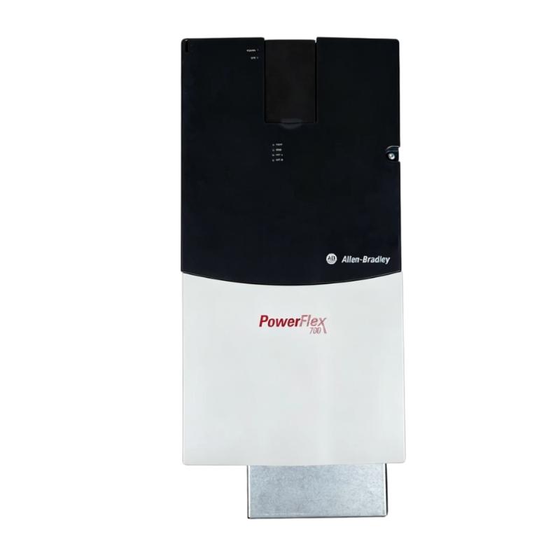
The Allen Bradley 20BF142A3ANNANC0 PowerFlex 700 AC Drive is a variable frequency drive for industrial AC motor applications. It sits between the plant power system and the motor, managing the electrical output required for controlled motor operation.
In production equipment, many motors need to operate at different speeds depending on process conditions. A variable-speed drive allows the motor to be coordinated with machine cycles, material flow, pump demand, ventilation requirements, or other changing operating conditions instead of relying on fixed-speed operation.
The 20BF142A3ANNANC0 belongs to the PowerFlex 700 drive family and can form part of a broader Allen Bradley automation architecture. A PLC or other controller can provide operating commands, while the drive handles the motor-side control and reports operating or diagnostic information back to the control system.
For replacement work, engineers should identify the complete catalog number and compare the existing application configuration. Motor characteristics, control method, wiring, communication arrangement, and programmed parameters should all be considered before commissioning a replacement drive.
Technical Specifications
| Parameter | Specification |
|---|---|
| Manufacturer | Allen Bradley |
| Model | 20BF142A3ANNANC0 |
| Product Family | PowerFlex 700 |
| Product Type | AC Drive |
| Primary Function | Variable-Speed AC Motor Control |
| System Role | Motor Speed and Power Control |
| Application | Industrial Automation / Motor Control |
| Dimensions | 850 × 403.9 × 275.5 mm |
| Weight | 71.44 kg |
Product Features
The 20BF142A3ANNANC0 is intended for applications where motor speed and operating behavior need to be managed electronically.
Key characteristics include:
- Allen Bradley PowerFlex 700 AC drive
- Model 20BF142A3ANNANC0
- Variable-speed AC motor control
- Suitable for industrial machinery and process equipment
- Interfaces between automation commands and motor operation
- Supports coordinated motor control within an automation system
- Provides drive operating and diagnostic information
- Suitable for production and material-handling equipment
- Useful for PowerFlex 700 maintenance and replacement projects
- Integrates with broader industrial control architectures
The drive should be matched to the complete motor-control application. Electrical supply, motor rating, mechanical load, control signals, and operating profile all influence the suitability of a particular drive configuration.
Working Principle
The PowerFlex 700 controls the motor by regulating the electrical output delivered from the drive to the AC motor.
A typical control path is:
Incoming AC Power → PowerFlex 700 → Controlled Motor Output → AC Motor → Mechanical Equipment
The operating sequence includes several functional stages:
-
Power Reception
The drive receives electrical power from the upstream distribution system.
-
Conversion
The internal power stage processes the incoming electrical energy for motor control.
-
Command Interpretation
A controller, operator, or configured control function establishes the required motor operating condition.
-
Output Control
The drive generates a controlled electrical output corresponding to the required motor operation.
-
Mechanical Response
The motor converts the electrical output into mechanical rotation and drives the connected equipment.
-
Status Monitoring
Drive operating conditions and diagnostic information can be used to monitor the motor-control system.
This arrangement enables the motor to respond to changing process requirements. For example, a conveyor may require different speeds during loading and unloading, while a pump may need its operating point adjusted as process demand changes.
Role in an Industrial Motor Control Architecture
The 20BF142A3ANNANC0 forms the bridge between the automation controller and the motor power circuit.
A simplified architecture is:
PLC / Controller → Control Command → PowerFlex 700 → AC Motor → Mechanical Load
The controller determines what the process requires, while the drive translates that requirement into controlled motor operation.
This division of responsibilities also simplifies troubleshooting. If a motor does not respond to a start or speed command, technicians can examine the system in stages:
Controller Command → Drive Input → Drive Status → Motor Output → Motor → Mechanical Load
This approach helps determine whether the issue originates from control logic, drive configuration, electrical connections, motor circuitry, or the driven machine.
Industrial Applications
| Application | Typical Use |
|---|---|
| Conveyor Systems | Controlling material-transfer speed |
| Pump Stations | Adjusting motor operation to process demand |
| Fan Systems | Variable-speed airflow control |
| Compressors | Managing motor operating conditions |
| Material Handling | Coordinating motor speed with production |
| Manufacturing Machinery | Controlling rotating equipment |
| Process Equipment | Matching motor operation to process requirements |
| Production Lines | Synchronizing motor-driven machinery |
The appropriate operating configuration depends on the motor and the mechanical process connected to the drive.
Installation and Maintenance
The drive should be treated as part of both the electrical and mechanical system during installation and servicing.
Recommended practices include:
- Confirm the complete 20BF142A3ANNANC0 catalog number.
- Verify the replacement drive against the existing installation.
- Record existing control and power connections.
- Document relevant drive parameters before removal.
- Isolate the incoming electrical supply before maintenance.
- Follow appropriate electrical discharge procedures.
- Inspect incoming power terminals.
- Check motor output wiring and cable condition.
- Verify grounding connections.
- Inspect the drive cooling path and cabinet ventilation.
- Check control and communication wiring.
- Confirm motor-related configuration before startup.
- Test operation at controlled speed.
- Monitor drive diagnostics during commissioning.
- Check motor response under normal load.
If the drive repeatedly trips during acceleration, the investigation should include acceleration settings, motor condition, motor cabling, mechanical load, and drive configuration. Replacing the drive without checking these factors may not resolve the underlying problem.
Related Components
The 20BF142A3ANNANC0 operates as part of a complete motor-control system.
| Component | Function |
|---|---|
| Allen Bradley PLC | Provides automation logic and control commands |
| PowerFlex 700 AC Drive | Controls motor electrical output |
| AC Motor | Produces mechanical rotation |
| Motor Cable | Connects the drive to the motor |
| Circuit Protection | Protects the incoming power circuit |
| Disconnect Device | Provides electrical isolation |
| HMI | Allows operator control and monitoring |
| Communication Network | Transfers commands and status data |
| Mechanical Load | Receives motor torque |
| Grounding System | Supports electrical safety |
Correct coordination between these components is important for reliable motor operation.
Recommended Related Models
| Model / Product Family | Product Type | Typical Application |
|---|---|---|
| Allen Bradley 20BF142A3ANNANC0 | PowerFlex 700 AC Drive | Variable-speed AC motor control |
| Allen Bradley PowerFlex 700 | AC Drive Family | Industrial motor control |
| Allen Bradley PowerFlex AC Drives | Variable Frequency Drive | Machine and process applications |
| Allen Bradley PLC Controllers | PLC Hardware | Automation and drive control |
| Allen Bradley HMI Systems | Operator Interface | Drive and machine monitoring |
Key Advantages
- Allen Bradley PowerFlex 700 AC drive.
- Model 20BF142A3ANNANC0.
- Suitable for variable-speed AC motor applications.
- Provides controlled motor power and speed management.
- Can receive commands from an industrial automation system.
- Suitable for machinery and process equipment.
- Supports drive-level monitoring and diagnostics.
- Useful for existing PowerFlex 700 installations.
- Suitable for maintenance and replacement applications.
Technical FAQs
What is the function of the 20BF142A3ANNANC0 in a motor-driven production system?
It serves as the drive-level controller between the electrical supply and the AC motor. It converts control requirements into controlled motor operation, allowing the motor to respond to changing production or process conditions.
Why should the mechanical load be checked when diagnosing a drive fault?
The drive responds to the torque and speed requirements imposed by the connected machine. A seized bearing, excessive load, blocked pump, or other mechanical problem can cause symptoms that appear to be electrical drive faults.
What information should be preserved before removing an existing PowerFlex 700?
Technicians should record the drive catalog number, power and control wiring, communication connections, relevant configuration parameters, and motor-related settings. This information can significantly reduce commissioning time after replacement.
What is the best way to evaluate a replacement drive during commissioning?
Begin with controlled operation rather than immediately applying the full production load. Verify the control command, motor direction, acceleration response, drive status, and motor behavior first, then gradually evaluate operation under the normal machine load.