
NewsNEWCENTER
Featured products
Contact Us
Allen Bradley 1606-XLBUFFER Power Supply Installation Guide
2026-08-25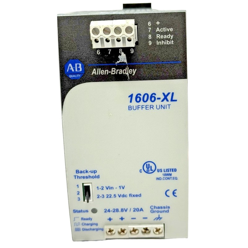
Table of Contents
- Allen Bradley 1606-XLBUFFER Power Supply Installation Overview
- Allen Bradley 1606-XLBUFFER Power Supply Function
- Allen Bradley 1606-XLBUFFER Installation Preparation
- Allen Bradley 1606-XLBUFFER Cabinet Layout and Mounting
- Allen Bradley 1606-XLBUFFER Wiring and DC Connection
- Allen Bradley 1606-XLBUFFER Setup and Initial Testing
- Allen Bradley 1606-XLBUFFER Commissioning with PLC Systems
- Allen Bradley 1606-XLBUFFER Installation Validation
- Allen Bradley 1606-XLBUFFER Field Commissioning Example
- Allen Bradley 1606-XLBUFFER Installation FAQ
- Allen Bradley 1606-XLBUFFER Overall Technical Summary
Allen Bradley 1606-XLBUFFER Power Supply Installation Overview
Allen Bradley 1606-XLBUFFER installation should be treated as part of the complete industrial DC power architecture. Because a buffer power unit can support control equipment during short interruptions or disturbances, correct wiring, charging behavior, load distribution, and commissioning are essential for reliable PLC operation.
The 1606-XLBUFFER is associated with the Allen Bradley 1606 power-supply family and is intended for industrial control-power applications where maintaining DC availability during brief input interruptions is important. In a practical cabinet, the buffer circuit may interact with a power supply, PLC Controller, I/O Modules, communication devices, Sensors, relays, and other DC loads.
The installation objective is therefore not simply to make the unit operate. The objective is to confirm that the complete power system can transition through the intended interruption or disturbance without causing unnecessary PLC resets or loss of critical control functions.
Allen Bradley 1606-XLBUFFER Power Supply Function
The Allen Bradley 1606-XLBUFFER is used within a DC control-power arrangement to provide buffering capability. In an automation cabinet, this type of device can help bridge short-duration interruptions and improve continuity for selected control loads.
From an engineering standpoint, the buffer should be considered together with the upstream DC supply and the connected load. The actual ride-through performance depends on the complete System Configuration, including load current, wiring, voltage conditions, and the devices connected to the protected DC bus.
Allen Bradley 1606-XLBUFFER Industrial Automation Role
- Supports continuity of DC control power during short disturbances.
- Works as part of an industrial DC power architecture.
- Can help protect PLC Controllers from brief supply interruptions.
- Can support selected I/O Modules and control interfaces.
- Provides a power-buffering layer between the normal DC source and critical loads.
It is important to distinguish buffering from unlimited backup power. The expected hold-up duration must always be evaluated against the actual load and the specified application requirements.
Allen Bradley 1606-XLBUFFER Installation Preparation
Before installing the 1606-XLBUFFER, review the complete DC power drawing. Determine which equipment is intended to remain powered during a short input interruption and which circuits can be allowed to drop out.
This distinction is especially important when a cabinet contains both PLC control electronics and high-current field loads. Supplying every load from the buffered circuit can reduce the available ride-through period and may create unnecessary stress on the DC power architecture.
Allen Bradley 1606-XLBUFFER Pre-Installation Checklist
- Confirm the exact 1606-XLBUFFER model.
- Review the approved electrical schematic.
- Identify the upstream DC power supply.
- Determine the intended buffered load.
- Calculate normal operating current.
- Identify high-current or intermittent loads.
- Verify conductor sizing and protection.
- Review cabinet temperature and ventilation.
- Confirm the intended PLC and I/O System Configuration.
Allen Bradley 1606-XLBUFFER Cabinet Layout and Mounting
Mechanical installation should provide adequate access for wiring, inspection, and maintenance. The 1606-XLBUFFER should be positioned according to the applicable installation requirements and should not be crowded by components that interfere with heat dissipation.
Cabinet temperature should be considered during engineering review. The actual thermal environment can be significantly different from the surrounding room, especially when drives, contactors, transformers, and multiple power supplies are installed inside the same enclosure.
Wire routing should also be planned before mounting. Keep high-current or electrically noisy circuits organized so that sensitive PLC, Sensor, and communication wiring is not unnecessarily exposed to switching disturbances.
Allen Bradley 1606-XLBUFFER Wiring and DC Connection
Allen Bradley 1606-XLBUFFER wiring should be performed only after the relevant electrical sources have been isolated according to the site’s safety procedure. The input and output connections must be identified from the actual product markings and approved electrical documentation.
Polarity is particularly important in DC control systems. Positive and negative conductors should be traced against the electrical drawing instead of being identified solely from conductor color.
Allen Bradley 1606-XLBUFFER Wiring Considerations
- Verify the upstream DC power source before connection.
- Confirm DC polarity.
- Use conductors suitable for the expected current.
- Provide the required branch protection.
- Keep connections mechanically secure.
- Separate sensitive signal wiring from high-noise circuits where appropriate.
- Clearly identify the buffered DC distribution circuit.
After wiring, inspect every relevant connection before energization. A high-resistance connection may remain invisible during low-load testing but become a significant problem when the buffered circuit carries its full operating load.
Allen Bradley 1606-XLBUFFER Setup and Initial Testing
The Allen Bradley 1606-XLBUFFER Setup process should establish a baseline before the PLC system is placed into normal operation. Start by verifying the upstream DC source and then check the buffered circuit under a controlled load.
1606-XLBUFFER INITIAL CHECK

1. Verify upstream DC source.
2. Confirm correct polarity.
3. Energize according to the approved procedure.
4. Measure DC voltage at the source.
5. Measure voltage at the buffered distribution point.
6. Connect the intended control load.
7. Monitor voltage during load changes.
8. Verify PLC Controller stability.
Do not use a simple power-cycle test as the only commissioning method. The purpose of the buffer is related to continuity during a disturbance, so the commissioning procedure should include an appropriate controlled interruption test when permitted by the system design and site safety procedure.
Allen Bradley 1606-XLBUFFER Commissioning with PLC Systems
Commissioning should verify the relationship between the 1606-XLBUFFER, the upstream power supply, and the protected control load. The PLC Controller should remain stable under the conditions for which the buffer has been selected.
A practical commissioning sequence is to begin with the control electronics and then introduce additional loads. Observe the voltage before, during, and after a controlled interruption. Record the response of the PLC, I/O Modules, communication interfaces, and other critical equipment.
Allen Bradley 1606-XLBUFFER Commissioning Observations
- Normal DC voltage before the interruption.
- Voltage behavior during the transition.
- PLC Controller operating state.
- I/O Module availability.
- Communication status.
- Sensor and instrumentation behavior.
- Recovery behavior when normal input power returns.
If a PLC resets during a controlled test, determine whether the cause is insufficient buffering time, excessive load, incorrect wiring, or an abnormal upstream condition before changing hardware.
Allen Bradley 1606-XLBUFFER Installation Validation
Validation should demonstrate that the installed 1606-XLBUFFER behaves predictably under representative operating conditions. The most useful test is not necessarily the largest possible load; it is the load condition that reflects the actual production System Configuration.
For a critical PLC Controller, document the normal operating voltage and the observed behavior during the approved interruption test. If remote I/O is included in the buffered circuit, measure the voltage at the remote distribution point as well.
Allen Bradley 1606-XLBUFFER Acceptance Checks
- Input power remains within the intended operating range.
- Buffered DC connections are correctly wired.
- Critical PLC equipment remains stable during the intended test.
- Remote I/O remains available when designed to be buffered.
- Communication interfaces recover correctly.
- Normal power returns without unexpected controller behavior.
- Final measurements are recorded for future Troubleshooting.
Allen Bradley 1606-XLBUFFER Field Commissioning Example
In one commissioning case, a control cabinet was designed to maintain the PLC Controller and critical I/O during short disturbances. The engineer first measured the normal DC bus and confirmed stable operation with the machine in standby.
During the controlled interruption test, the PLC remained online, but one remote I/O group showed an intermittent communication event. The initial assumption was that the buffer had failed.
Instead of replacing the 1606-XLBUFFER immediately, the engineer measured the voltage at three locations: the upstream DC source, the buffer output, and the remote I/O distribution point. The source and buffer measurements remained stable relative to the expected system behavior, while the remote point showed a larger transient drop.
The investigation then moved to the distribution wiring. A terminal connection in the remote branch was found to have excessive resistance. Under normal operation it did not produce an obvious problem, but during the transition it contributed to a temporary voltage disturbance at the remote I/O equipment.
After correcting the connection, the controlled interruption test was repeated. The PLC and remote I/O remained stable, and the original communication event was not reproduced.
This is a useful field lesson: when a buffered system fails to maintain one downstream device, always compare the voltage at the buffer with the voltage at the actual load before concluding that the buffer itself is defective.
Allen Bradley 1606-XLBUFFER Installation FAQ
What is the purpose of the Allen Bradley 1606-XLBUFFER?
The 1606-XLBUFFER is used within a DC control-power architecture to provide buffering capability during short-duration supply disturbances. Its actual performance depends on the complete power-system configuration and connected load.
Should the entire control cabinet be connected to the buffered circuit?
Not necessarily. The buffered load should be selected according to the application. High-current or non-critical loads can consume available buffering capacity without providing additional value for PLC control continuity.
Why should the remote PLC or I/O voltage be measured during commissioning?
Voltage can change between the buffer and the final load because of cable resistance and connection quality. Load-side measurements provide evidence about the actual voltage available to the equipment.
Can the 1606-XLBUFFER prevent every PLC power fault?
No. Buffering is intended for the conditions supported by the system design. It does not eliminate problems caused by sustained power loss, severe overload, incorrect wiring, downstream short circuits, or equipment faults.
What information should be recorded during 1606-XLBUFFER Commissioning?
Record normal DC voltage, connected load conditions, PLC and I/O status, behavior during the approved interruption test, recovery behavior, and important load-side voltage measurements. These records provide a useful baseline for future Fault Diagnosis.
Allen Bradley 1606-XLBUFFER Overall Technical Summary
The Allen Bradley 1606-XLBUFFER Installation Guide should be applied to the entire DC power architecture rather than treating the buffer as an isolated component. Correct wiring, load selection, cabinet installation, and staged Commissioning are essential for achieving predictable control-power continuity.
For field engineers, the most useful validation method is to establish normal operating measurements and then observe the complete power path during an approved disturbance test. Comparing the buffer output with the voltage at critical PLC and I/O loads can reveal distribution problems that are easily mistaken for hardware failure.
Once the 1606-XLBUFFER has passed Setup, wiring inspection, load validation, and controlled Commissioning, the recorded results should become part of the cabinet maintenance documentation. This baseline can significantly improve future Troubleshooting and Fault Diagnosis when PLC Controllers, Modules, Sensors, or communication equipment experience unexplained power-related interruptions.