

ProductPRODUCT
Featured products



Contact Us
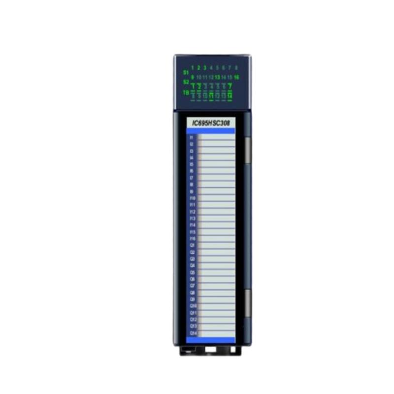
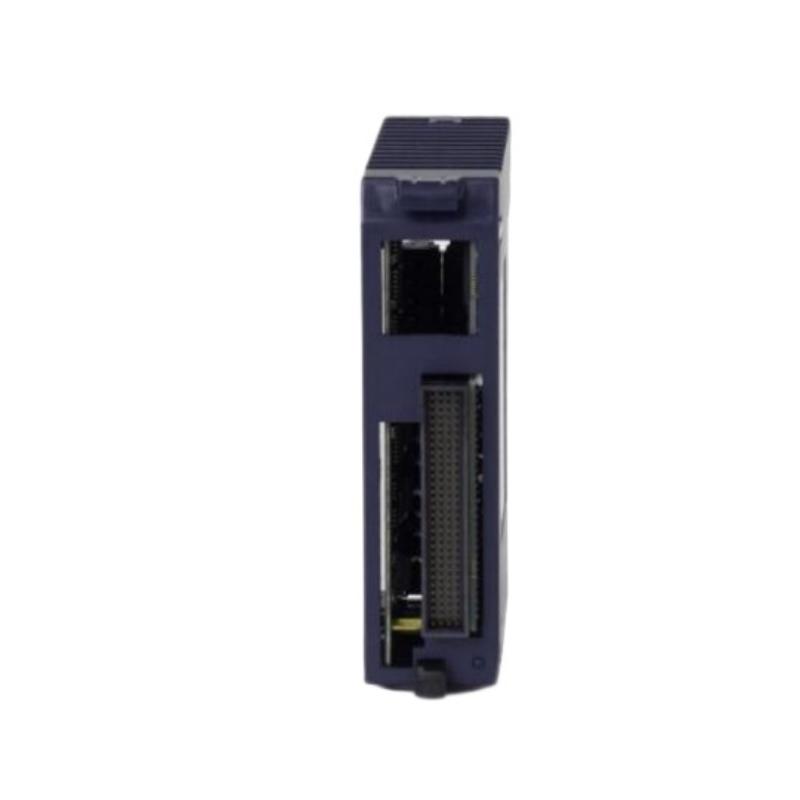
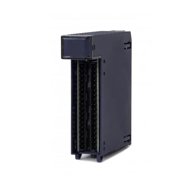
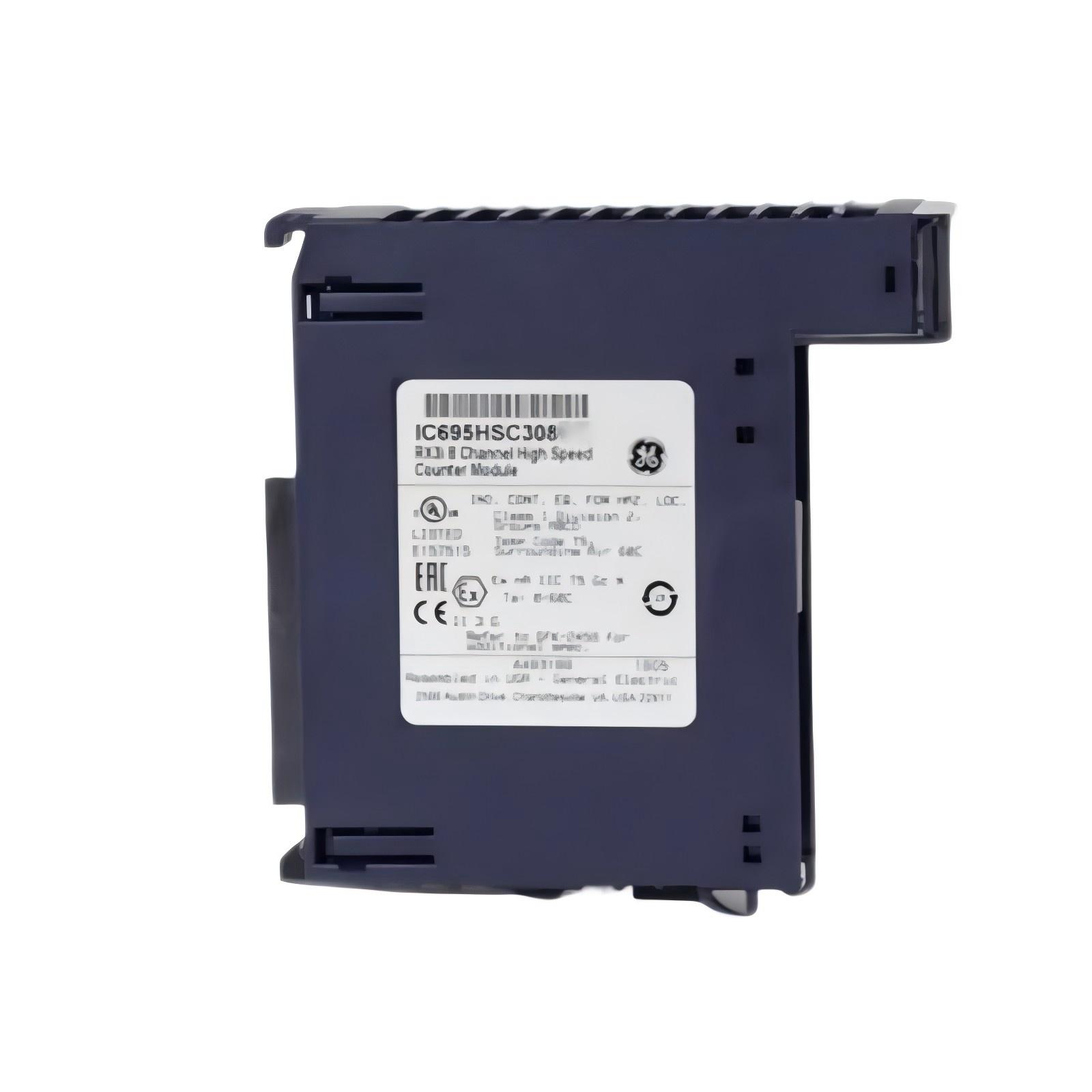
- GE
- IC695HSC308
- RX3i High-Speed Counter
- USA
- 132 x 50.8 x 70 mm
- 0.336 kg
- Xiamen, China
- New & In Stock
- T/T, PayPal, Western Union
- 1 Year
- 1-3 Working Days
- DHL, UPS, TNT, FedEx and EMS.
- 24-Hour Service
- COO
- 51
Our advantage

Global Logistics
We have a 10-year logistics and express cooperation agreement, so our products can be shipped to any place in the world.

Brand new and original
Our products are imported in bulk from the place of origin. Because of the cooperative relationship, our products are all original and 100% new.

24-hour service
We provide 7*24 hours service to our customers. We will be there whenever you need us.

Price advantage
All our products are priced very favorably because we have our own warehouse and supply.
| Company Information | |||
| [email protected] | |||
| Mobile | +8615980777398 | ||
| +8615980777398 | |||
| 15980777398 |
Product Overview
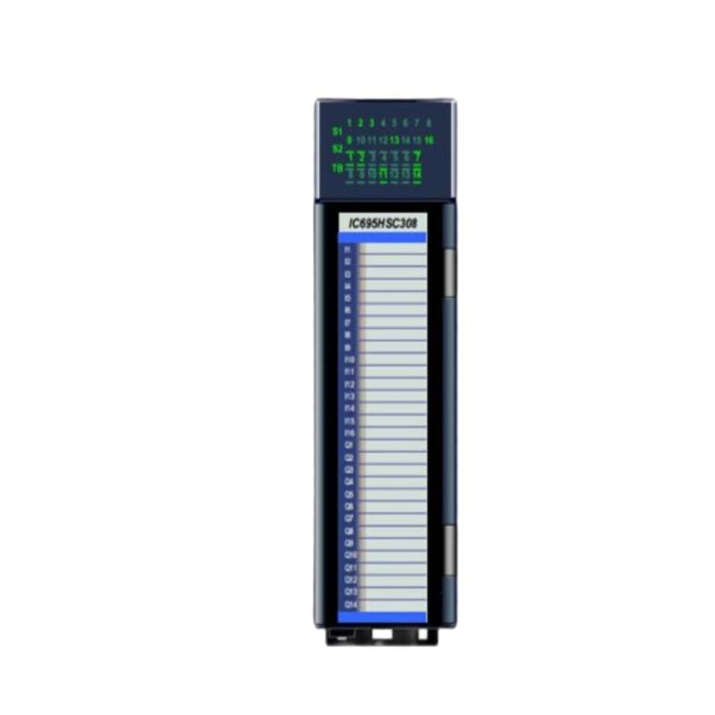
The GE IC695HSC308 is an RX3i High-Speed Counter Module designed for industrial automation applications that require accurate counting of high-frequency pulses and rapid detection of fast-changing field signals. Unlike conventional PLC input processing, which may not be suitable for very fast pulse trains, a dedicated high-speed counter provides specialized hardware for capturing and processing high-speed events.
The module can be used in applications involving rotary encoders, proximity sensors, pulse generators, counting systems, and other devices that produce repetitive high-frequency signals.
The specified dimensions of the GE IC695HSC308 are 132 × 50.8 × 70 mm, with a weight of approximately 0.336 kg.
In an RX3i control architecture, the high-speed counter module provides a specialized interface between fast field signals and the controller application. It can allow the control system to monitor pulse counts and related events without depending entirely on the normal PLC scan cycle.
This guide covers the product’s technical characteristics, operating principle, installation, commissioning, signal troubleshooting, preventive maintenance, and replacement procedures.
Product Identification
| Parameter | Specification |
|---|---|
| Manufacturer | GE |
| Product Family | PACSystems RX3i |
| Model | IC695HSC308 |
| Product Type | RX3i High-Speed Counter |
| Primary Function | High-Speed Pulse Counting |
| Dimensions | 132 × 50.8 × 70 mm |
| Weight | 0.336 kg |
| Installation | RX3i Control System |
| Application | High-Speed Industrial Measurement and Control |
| System Role | High-Speed Counting / Pulse Processing |
Technical Specifications
| Technical Item | Specification |
|---|---|
| Product Series | PACSystems RX3i |
| Part Number | IC695HSC308 |
| Module Type | High-Speed Counter |
| Height | 132 mm |
| Width | 50.8 mm |
| Depth | 70 mm |
| Weight | Approximately 0.336 kg |
| Primary Function | Pulse Counting |
| Signal Type | High-Speed Digital Pulses |
| Installation Environment | Industrial Control Cabinet |
| System Integration | RX3i Automation Architecture |
What Is the GE IC695HSC308?
The IC695HSC308 is a specialized high-speed counting module used when a standard PLC input process may not provide the required response to fast pulse signals.
A conventional digital input may be affected by the controller’s scan cycle and application execution time. A high-speed counter is designed specifically to detect and process rapid pulse events.
Typical signal sources include:
- Rotary encoders
- Proximity sensors
- Pulse generators
- Position sensors
- Speed sensors
- Production counters
- Metering equipment
- Rotational monitoring devices
A simplified signal path is:
Pulse Generator / Sensor
↓
IC695HSC308
↓
High-Speed Counting
↓
RX3i Controller
↓
PLC Application
↓
Machine / Process Control
High-Speed Counter Working Principle
The module performs specialized processing of incoming pulse signals.
1. Signal Detection
The module receives a digital pulse signal from an external sensor or pulse-producing device.
2. High-Speed Capture
The module detects incoming events using dedicated high-speed processing rather than relying exclusively on the standard PLC scan.
3. Count Processing
Detected pulses are accumulated according to the configured counting operation.
4. Status Processing
The module provides count and status information to the control application.
5. Controller Integration
The RX3i controller can use the counter information for machine sequencing, measurement, position monitoring, or other control functions.
Why Use a High-Speed Counter?
High-speed counting is useful when the input frequency is too fast for conventional software-based counting.
For example, a production machine may use a proximity sensor to detect every passing product.
If the sensor produces:
Pulse → Pulse → Pulse → Pulse → Pulse
at a high frequency, a conventional input-processing approach may not reliably capture every event.
A dedicated high-speed counter is designed specifically for this type of application.
Typical Industrial Applications
The GE IC695HSC308 can be integrated into applications such as:
- Production counting
- Conveyor systems
- Rotary encoder monitoring
- Motor speed measurement
- Position monitoring
- Packaging machinery
- Material handling
- Length measurement
- Machine synchronization
- Pulse-based metering
- High-speed manufacturing
- Automated inspection systems
Application Example: Production Counting
Consider a conveyor carrying manufactured components.
A sensor generates one pulse every time a product passes a specific point.
The signal path can be represented as:
Product
↓
Proximity Sensor
↓
Pulse Signal
↓
IC695HSC308
↓
Count Value
↓
RX3i Controller
↓
Production Logic
The controller can then use the count value to coordinate production sequences, packaging operations, or machine interlocks.
Application Example: Rotary Speed Monitoring
A rotating machine may use an encoder or pulse-generating sensor.
As the shaft rotates:
Rotation → Pulse Train → High-Speed Counter → Controller
The controller can use the processed information for:
- Speed monitoring
- Position tracking
- Machine synchronization
- Production timing
- Alarm generation
System Integration
A typical RX3i system using the IC695HSC308 may include:
| Component | Function |
|---|---|
| RX3i CPU | Central control processing |
| IC695HSC308 | High-speed pulse counting |
| RX3i Power Supply | System power |
| RX3i Backplate | Rack mounting and backplane connection |
| Proximity Sensor | Pulse generation |
| Rotary Encoder | Position or speed feedback |
| Digital I/O Modules | General-purpose signals |
| Analog I/O Modules | Analog measurements |
| Engineering Workstation | Programming and diagnostics |
| Machine Actuators | Physical control |
Installation Guide
1. Verify the Module
Confirm:
GE IC695HSC308 RX3i High-Speed Counter
Verify the part number before installation.
2. Inspect the Module
Check:
- Housing
- Connectors
- Mounting interface
- Terminal interfaces
- Signs of physical damage
- Signs of overheating
Do not install a module that has visible damage.
3. Confirm System Configuration
Verify:
- RX3i rack
- Controller
- Power supply
- Module position
- High-speed counter configuration
- Sensor type
- Wiring arrangement
4. Prepare the Control Cabinet
Specified dimensions:
132 × 50.8 × 70 mm
Provide enough space for:
- Module installation
- Sensor wiring
- Terminal access
- Ventilation
- Maintenance
- Cable routing
Avoid excessive heat, moisture, vibration, and electromagnetic interference.
5. Identify the Pulse Source
Before wiring, determine the type of field device providing the pulse signal.
Examples include:
- Proximity sensor
- Encoder
- Pulse generator
- Machine sensor
Confirm that the sensor’s electrical characteristics are suitable for the intended input configuration.
6. Shut Down the System
Before physical installation:
- Stop the machine.
- Shut down the control system.
- Remove power according to the approved procedure.
- Verify a safe maintenance condition.
- Apply lockout/tagout procedures where required.
7. Install the Module
Install the IC695HSC308 in the designated RX3i rack position.
Verify:
- Correct orientation
- Correct slot
- Proper alignment
- Complete connector engagement
- Secure retention
8. Connect the Sensor
Connect the pulse-generating device according to the approved electrical design.
Pay attention to:
- Signal polarity
- Common/return connections
- Shielding
- Cable routing
- Grounding
- Signal integrity
9. Separate Signal Wiring
High-speed pulse signals can be sensitive to electrical interference.
Where appropriate, route sensor cables separately from:
- Motor power cables
- Variable-frequency drive wiring
- High-current conductors
- Switching power circuits
10. Verify Configuration
Confirm:
- Counter mode
- Input assignment
- Count direction
- Preset or limit parameters
- Required status behavior
- Controller data mapping
Commissioning Procedure
Step 1 — Physical Inspection
Verify the module, wiring, sensor, and rack installation.
Step 2 — Power Verification
Confirm stable control-system power.
Step 3 — Module Startup
Power up the RX3i system.
Step 4 — Status Check
Observe the module and controller diagnostics.
Step 5 — Sensor Verification
Activate the pulse source manually or under controlled machine operation.
Step 6 — Count Verification
Confirm that the counter responds to incoming pulses.
Step 7 — Direction Verification
If applicable, verify that the configured counting direction matches machine movement.
Step 8 — Scaling / Application Verification
Confirm that the controller interprets the count correctly for the application.
Step 9 — Machine Test
Operate the machine under controlled conditions and compare expected pulses with actual counts.
Troubleshooting Guide
Fault 1 — Counter Does Not Count
Possible causes:
- No sensor signal
- Incorrect wiring
- Sensor power problem
- Incorrect input configuration
- Module installation problem
- Faulty sensor
Recommended Checks
- Verify sensor power.
- Check signal wiring.
- Observe input status.
- Inspect module diagnostics.
- Test the sensor independently.
Fault 2 — Count Is Lower Than Expected
Possible causes:
- Pulse frequency exceeds application capability
- Poor signal quality
- Electrical interference
- Sensor positioning problem
- Incorrect configuration
- Wiring problem
Check the pulse source and signal integrity before replacing the module.
Fault 3 — Count Increases Without Machine Movement
This often indicates unwanted pulses or electrical noise.
Possible causes:
- Electromagnetic interference
- Incorrect grounding
- Shielding problem
- Noisy sensor signal
- Damaged cable
- Loose connection
Inspect the complete signal path.
Fault 4 — Counter Counts in the Wrong Direction
Possible causes:
- Incorrect sensor arrangement
- Incorrect configuration
- Reversed signal relationship
- Wiring error
Verify the configured direction and the actual sensor signal relationship.
Fault 5 — Count Resets Unexpectedly
Possible causes:
- Controller reset
- Power interruption
- Incorrect reset logic
- Application configuration
- External reset signal
Review controller and module diagnostics together.
Fault 6 — Intermittent Pulse Detection
Possible causes:
- Loose connector
- Damaged sensor cable
- Electrical noise
- Sensor instability
- Poor grounding
- Excessive cable length
- Environmental interference
Monitor the signal while the machine is operating.
Fault 7 — Sensor Works but PLC Value Is Incorrect
Possible causes:
- Incorrect data mapping
- Application logic error
- Configuration mismatch
- Scaling problem
- Counter parameter issue
Check the complete chain:
Sensor → HSC Module → Controller Data → PLC Logic
Fault 8 — High-Speed Counter Reports a Diagnostic Fault
Possible causes:
- Configuration problem
- Module hardware issue
- Input condition problem
- Power problem
- Rack communication issue
Record diagnostic information before resetting the system.
Fault 9 — Counter Works at Low Speed but Fails at High Speed
Possible causes:
- Signal integrity problem
- Incorrect sensor selection
- Electrical interference
- Wiring limitations
- Configuration issue
- Application timing problem
This fault should be investigated under controlled high-speed conditions.
Fault 10 — Counter Fails After Module Replacement
Possible causes:
- Incorrect hardware configuration
- Incorrect module position
- Wiring not restored correctly
- Counter parameters not restored
- Sensor connection problem
Compare the replacement installation with the original configuration and wiring documentation.
Diagnostic Workflow
A practical high-speed counter troubleshooting sequence is:
Power Supply
↓
RX3i Rack
↓
IC695HSC308
↓
Sensor Power
↓
Sensor Output
↓
Signal Cable
↓
Counter Input
↓
Controller Data
↓
PLC Application
↓
Machine Operation
This method prevents technicians from immediately replacing the HSC module when the actual fault is caused by the sensor, wiring, or application configuration.
Signal Integrity Considerations
High-speed counting depends heavily on signal quality.
Important considerations include:
Cable Routing
Keep high-speed sensor cables away from major sources of electrical noise where practical.
Shielding
Use appropriate shielding practices for the application.
Grounding
Ensure the control system and field devices have appropriate grounding.
Sensor Installation
Ensure proximity sensors and encoders are securely mounted.
Connector Security
Loose connectors can produce intermittent pulse detection.
Mechanical Stability
Vibration can cause a sensor to move and generate inconsistent signals.
Preventive Maintenance
Module Inspection
Inspect:
- Housing
- Connectors
- Mounting
- Terminal interfaces
- Status indicators
Sensor Inspection
Check:
- Sensor position
- Mounting
- Power
- Signal output
- Cable condition
Wiring Inspection
Check:
- Loose terminals
- Damaged cables
- Shielding
- Grounding
- Cable routing
System Inspection
Monitor:
- Controller diagnostics
- Counter status
- Count consistency
- Machine speed
- Environmental conditions
Preventive Maintenance Checklist
| Inspection Item | Recommended Action |
|---|---|
| HSC Module | Inspect housing and connectors |
| Module Seating | Verify secure rack installation |
| Sensor | Check mounting and operation |
| Sensor Cable | Inspect for damage |
| Signal Wiring | Verify connections |
| Shielding | Check signal-integrity practices |
| Grounding | Verify appropriate grounding |
| Count Values | Compare with expected results |
| Controller Diagnostics | Review abnormal events |
| Cabinet Environment | Monitor temperature and contamination |
High-Speed Counter Replacement Procedure
Step 1 — Record Current Configuration
Document:
- Counter parameters
- Input assignments
- Sensor connections
- PLC data mapping
- Application settings
Step 2 — Back Up the PLC
Save the application and hardware configuration.
Step 3 — Stop the Machine
Place the controlled equipment in a safe state.
Step 4 — Remove Power
Follow the approved shutdown and lockout/tagout procedure.
Step 5 — Label Wiring
Identify all sensor and signal connections.
Step 6 — Remove the Existing Module
Carefully disconnect and remove the existing HSC module.
Step 7 — Inspect the Rack
Check the backplane connection and mounting interface.
Step 8 — Install the Replacement
Install the replacement IC695HSC308.
Step 9 — Reconnect Sensor Wiring
Reconnect all field signal connections according to the documented wiring arrangement.
Step 10 — Restore Configuration
Restore the validated hardware and application configuration.
Step 11 — Restore Power
Power up the system.
Step 12 — Verify Module Status
Check diagnostics and module status.
Step 13 — Test Pulse Detection
Generate controlled pulses and verify the count.
Step 14 — Test Machine Operation
Operate the machine at controlled speeds.
Step 15 — Verify Count Accuracy
Compare the module’s count information with the expected number of pulses.
Key Advantages
- Designed for PACSystems RX3i automation systems
- Dedicated high-speed pulse-counting functionality
- Suitable for fast machine signals
- Useful for encoder and sensor applications
- Supports production counting
- Suitable for speed and position-related applications
- Compact 132 × 50.8 × 70 mm form factor
- Approximately 0.336 kg weight
- Reduces reliance on conventional PLC scan-based counting
- Suitable for industrial machine and process automation
Frequently Asked Questions
What is the GE IC695HSC308?
The GE IC695HSC308 is an RX3i High-Speed Counter Module designed to process fast pulse signals for industrial automation applications.
What are the dimensions?
The specified dimensions are:
132 × 50.8 × 70 mm
What is the weight?
Approximately 0.336 kg.
What is a high-speed counter used for?
It is used to process high-frequency pulses from devices such as proximity sensors, encoders, and pulse generators.
Why use an HSC instead of a normal digital input?
A dedicated high-speed counter is designed to capture rapid pulse events without relying entirely on the normal PLC scan cycle.
Why does the counter not count?
Check sensor power, wiring, signal configuration, module installation, sensor operation, and diagnostic information.
Why does the counter produce extra counts?
Unwanted counts can result from electrical noise, poor shielding, grounding problems, unstable sensors, damaged cables, or incorrect signal wiring.
Why does counting fail at high machine speed?
Possible causes include poor signal integrity, sensor limitations, electrical interference, wiring problems, or configuration issues.
What should be checked after replacing the HSC module?
Verify module installation, sensor wiring, hardware configuration, counter parameters, PLC data mapping, pulse detection, and count accuracy.
Conclusion
The GE IC695HSC308 RX3i High-Speed Counter is a specialized industrial automation module designed for applications requiring reliable processing of fast pulse signals. With specified dimensions of 132 × 50.8 × 70 mm and a weight of approximately 0.336 kg, it provides a compact interface for high-speed counting applications within the RX3i platform.
Its primary value is the ability to process rapid pulse events for applications such as production counting, encoder monitoring, speed measurement, position feedback, and machine synchronization. By using a dedicated high-speed counting function, the control system can handle pulse-driven applications that may be difficult to manage through conventional PLC input processing alone.
Successful installation requires correct rack integration, appropriate sensor selection, secure signal wiring, suitable grounding and shielding practices, and accurate counter configuration. During commissioning, technicians should verify the sensor signal, pulse detection, count direction, controller data, and actual machine performance.
When troubleshooting the IC695HSC308, the module should not automatically be considered the source of a counting problem. Sensor operation, wiring, signal integrity, configuration, controller data mapping, and mechanical conditions should all be checked systematically.
With proper installation, preventive maintenance, reliable signal wiring, configuration backups, and regular verification of count performance, the IC695HSC308 can provide dependable high-speed pulse processing for demanding RX3i industrial automation applications.