

ProductPRODUCT
Featured products



Contact Us
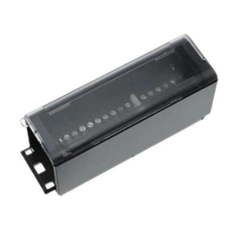
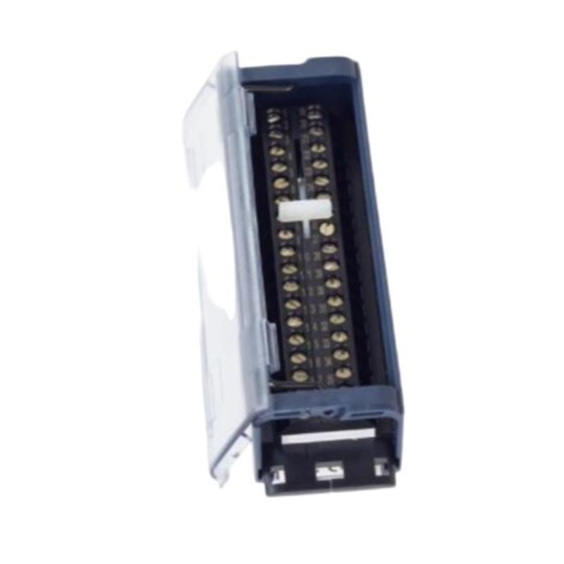
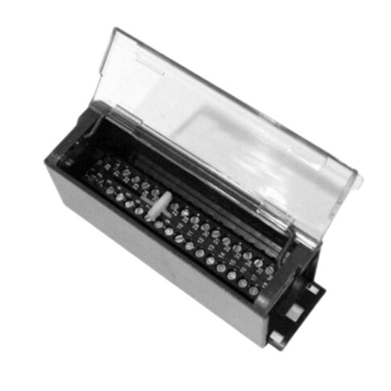
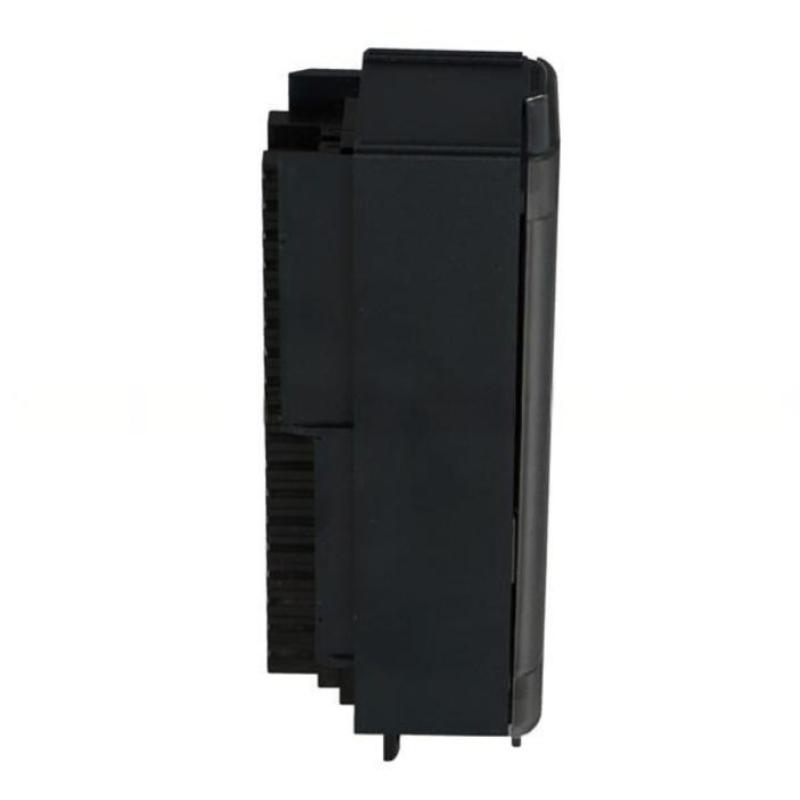
- GE
- IC694TBB132
- Box-Type High-Density Terminal Block
- USA
- 120 × 60 × 40 mm
- 0.14 kg
- Xiamen, China
- New & In Stock
- T/T, PayPal, Western Union
- 1 Year
- 1-3 Working Days
- DHL, UPS, TNT, FedEx and EMS.
- 24-Hour Service
- COO
- 68
Our advantage

Global Logistics
We have a 10-year logistics and express cooperation agreement, so our products can be shipped to any place in the world.

Brand new and original
Our products are imported in bulk from the place of origin. Because of the cooperative relationship, our products are all original and 100% new.

24-hour service
We provide 7*24 hours service to our customers. We will be there whenever you need us.

Price advantage
All our products are priced very favorably because we have our own warehouse and supply.
| Company Information | |||
| [email protected] | |||
| Mobile | +8615980777398 | ||
| +8615980777398 | |||
| 15980777398 |
Product Overview
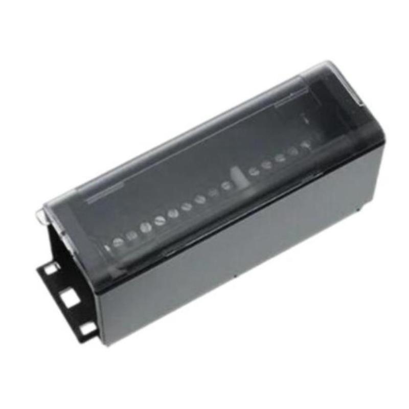
The GE IC694TBB132 Box-Type High-Density Terminal Block is a compact industrial wiring component used to provide an organized termination and connection point between compatible PLC equipment and field wiring. In an industrial automation cabinet, terminal blocks provide the physical interface through which sensors, switches, actuators, control circuits, and other field devices are connected to the PLC system.
The IC694TBB132 is identified as a Box-Type High-Density Terminal Block, making it suitable for applications where multiple electrical connections need to be arranged efficiently in a limited cabinet area.
The specified dimensions of this model are 120 × 60 × 40 mm, with a specified weight of 0.14 kg.
Unlike a PLC CPU or I/O module, a terminal block does not execute control logic. Its function is primarily electrical connection, circuit organization, and wiring distribution. Consequently, installation quality has a direct impact on PLC signal reliability.
Product Identification
| Parameter | Specification |
|---|---|
| Manufacturer | GE |
| Series | IC694 |
| Model | IC694TBB132 |
| Product Type | Box-Type High-Density Terminal Block |
| Main Function | Field Wiring Termination |
| Application | PLC and Industrial Automation |
| Dimensions | 120 × 60 × 40 mm |
| Weight | 0.14 kg |
| Installation | Industrial Control Cabinet |
| System Role | Electrical Connection Interface |
| Design | Box-Type |
| Density | High-Density Terminal Arrangement |
Technical Specifications
| Technical Item | Specification |
|---|---|
| Manufacturer | GE |
| Model | IC694TBB132 |
| Product Category | High-Density Terminal Block |
| Terminal Type | Box-Type |
| Main Function | Field Wiring Interface |
| Dimensions | 120 × 60 × 40 mm |
| Weight | 0.14 kg |
| Typical Environment | Industrial Control Cabinet |
| Application | PLC / Automation Wiring |
| Signal Type | Dependent on Associated System |
| Mounting | System-Compatible Installation |
| Maintenance | Wiring and Connection Inspection |
The exact terminal numbering, conductor-size range, electrical ratings, associated module compatibility, and mounting arrangement should be verified against the intended system configuration before installation.
What Is the GE IC694TBB132?
The IC694TBB132 provides a structured termination point for electrical conductors within a PLC control architecture.
A typical signal path can be represented as:
Field Device
↓
Field Cable
↓
IC694TBB132
↓
PLC I/O Interface
↓
PLC CPU
↓
Control Program
For an output circuit, the signal path operates in the opposite direction:
PLC CPU
↓
I/O Interface
↓
IC694TBB132
↓
Field Wiring
↓
Actuator
This makes the terminal block an important physical connection point even though it does not perform PLC processing.
Main Functions
Field Wiring Termination
The terminal block provides an organized location for connecting field conductors.
Depending on the application, connected circuits may include:
- Proximity sensors
- Limit switches
- Pushbuttons
- Solenoid valves
- Relays
- Indicator circuits
- Interlock signals
- Discrete control circuits
The actual function of each terminal depends on the associated PLC module and electrical design.
High-Density Wiring
The high-density design is useful when many circuits must be accommodated within a limited cabinet area.
A structured terminal arrangement can make it easier to:
- Identify individual circuits
- Trace wiring
- Perform maintenance
- Replace equipment
- Isolate faults
- Update documentation
Good terminal organization becomes increasingly important as the number of field circuits increases.
Installation Guide
1. Verify Model Identification
Before installation, confirm:
GE IC694TBB132
Compare the model number with the control-panel drawings and bill of materials.
Do not install a visually similar terminal block without confirming system compatibility.
2. Inspect the Terminal Block
Check the IC694TBB132 for:
- Cracked housing
- Damaged terminal points
- Broken mechanical components
- Corrosion
- Contamination
- Discoloration
- Signs of overheating
Do not install a component with visible physical damage.
3. Confirm Compatibility
Before installation, verify:
- Associated PLC equipment
- I/O module compatibility
- Terminal assignment
- Mechanical arrangement
- Electrical ratings
- Wiring configuration
- Mounting requirements
The physical dimensions of a terminal block do not by themselves establish electrical compatibility.
4. Verify Dimensions
The specified dimensions are:
120 × 60 × 40 mm
Ensure there is sufficient space around the terminal block for:
- Wire entry
- Cable bending
- Terminal access
- Labeling
- Inspection
- Maintenance
Avoid routing cables in a way that places continuous mechanical stress on the terminals.
5. Verify Weight
The specified weight is:
0.14 kg
The terminal block itself is lightweight, but the connected field cables may add considerable mechanical load.
Where necessary, provide cable support independently of the terminal connections.
6. Isolate Electrical Power
Before installing, removing, or rewiring the terminal block:
- Stop the machine safely.
- Shut down the applicable control system.
- Isolate electrical power.
- Apply lockout/tagout procedures.
- Verify the absence of hazardous voltage.
- Discharge stored energy where applicable.
- Follow the plant’s electrical safety procedures.
A stopped PLC does not necessarily mean that all terminal circuits are de-energized.
7. Install the Terminal Block
Position the IC694TBB132 in the designated location.
Verify:
- Correct orientation
- Proper alignment
- Secure mounting
- Adequate clearance
- Accessibility for wiring
Do not force the component into position.
8. Prepare Field Conductors
Before making connections:
- Identify each wire
- Confirm cable numbers
- Inspect insulation
- Prepare conductor ends correctly
- Avoid damaged strands
- Apply appropriate wire identification
Correct conductor preparation is important for long-term connection reliability.
9. Connect Field Wiring
Connect the conductors according to the approved wiring diagram.
For each circuit, verify:
- Terminal number
- Signal designation
- Voltage
- Polarity where applicable
- Common/reference
- Device destination
Never depend solely on memory when reconnecting high-density wiring.
Terminal Identification
A structured labeling system can greatly simplify maintenance.
For example:
| Identification | Description |
|---|---|
| Terminal Number | Physical connection |
| Cable Number | Field cable identification |
| Device Name | Connected field equipment |
| PLC Address | Associated control point |
| Signal Type | Input / Output / Common |
The actual naming convention should follow the plant’s engineering documentation.
Wiring Best Practices
Maintain Cable Organization
Route conductors neatly and avoid unnecessary loops around the terminal block.
Prevent Mechanical Stress
Heavy cables should not hang directly from terminal connections.
Use appropriate cable supports and strain relief.
Separate Power and Signal Wiring
Where practical, separate control and signal wiring from:
- Motor cables
- High-current power conductors
- VFD output cables
- Welding circuits
- Other high-noise electrical sources
This can help reduce electrical interference.
Commissioning Procedure
Step 1 – Mechanical Inspection
Verify:
- Terminal block is secure
- Housing is intact
- Mounting is correct
- Cable routing is acceptable
Step 2 – Wiring Verification
Compare every connection against the wiring documentation.
Check:
- Terminal numbers
- Cable identifiers
- Signal names
- Common connections
- Device destinations
Step 3 – Continuity Testing
With circuits safely isolated and where appropriate, perform continuity checks on critical wiring.
Look for:
- Open circuits
- Short circuits
- Cross-connections
- Incorrect terminations
Step 4 – Restore Power
Restore electrical power according to the approved startup procedure.
Observe the PLC and connected equipment for abnormal conditions.
Step 5 – Verify PLC Signals
Operate representative field devices and confirm that the associated PLC inputs respond correctly.
For output circuits, activate the corresponding PLC output and verify that the intended field device responds.
Step 6 – Functional Test
Operate the machine or process through the required test sequence.
Verify:
- Inputs
- Outputs
- Interlocks
- Alarms
- Actuator responses
- Sequence operation
Troubleshooting Guide
Fault 1 – PLC Does Not Receive a Field Signal
Possible Causes
- Loose terminal
- Incorrect terminal assignment
- Broken conductor
- Incorrect cable
- Failed field device
- Faulty associated I/O module
- Damaged terminal connection
Diagnostic Path
Trace:
Field Device → Field Cable → IC694TBB132 → I/O Module → PLC
Fault 2 – Signal Is Intermittent
Intermittent signals can be caused by:
- Loose terminal connections
- Poor conductor preparation
- Vibration
- Corrosion
- Damaged wiring
- Mechanical cable stress
Inspect the entire connection path rather than immediately replacing the terminal block.
Fault 3 – Several Signals Fail at Once
When multiple signals disappear simultaneously, investigate shared circuits first.
Possible causes include:
- Common connection failure
- Shared power supply
- Associated connector
- I/O module issue
- Wiring harness problem
- Terminal block connection problem
A common terminal or shared circuit can affect several signals simultaneously.
Fault 4 – Wrong Signal Appears at PLC
Possible causes include:
- Cross-wired conductors
- Incorrect terminal
- Wrong cable identification
- Incorrect PLC address
- Field device problem
Compare the physical wiring with the engineering documentation.
Fault 5 – Terminal Becomes Hot
Abnormal heating may indicate:
- Excessive current
- Loose connection
- Incorrect conductor size
- Poor termination
- Overloaded circuit
- Damaged terminal
Safely isolate the circuit and investigate the underlying electrical problem.
Do not treat terminal heating as a normal operating condition.
Fault 6 – Connection Frequently Becomes Loose
Potential causes include:
- Vibration
- Improper installation
- Mechanical cable tension
- Repeated maintenance
- Incorrect conductor preparation
Inspect the cable support and termination method as well as the terminal itself.
Fault 7 – Corrosion Is Present
Potential causes include:
- High humidity
- Condensation
- Chemical contamination
- Poor cabinet sealing
- Aggressive environmental conditions
Correcting the environmental cause is important to prevent recurrence.
Fault 8 – PLC Input Remains OFF
Check the signal path:
- Field sensor
- Sensor power
- Field cable
- IC694TBB132 terminal
- Associated I/O module
- PLC configuration
This approach helps distinguish wiring faults from PLC faults.
Fault 9 – PLC Output Does Not Reach the Field Device
Trace:
PLC Program → CPU → I/O Module → IC694TBB132 → Field Wiring → Load
Verify each stage separately.
Fault 10 – Fault Appears Immediately After Maintenance
If the equipment operated correctly before maintenance and failed immediately afterward, inspect for:
- Swapped conductors
- Incorrect terminal
- Loose wire
- Incorrect common
- Misidentified cable
- Incomplete reconnection
Fault Diagnosis Flow
For input circuits:
Field Device
↓
Field Cable
↓
IC694TBB132
↓
I/O Module
↓
PLC CPU
↓
PLC Program
For output circuits:
PLC Program
↓
CPU
↓
I/O Module
↓
IC694TBB132
↓
Field Wiring
↓
Actuator
Following the complete signal path prevents unnecessary replacement of functioning PLC hardware.
Preventive Maintenance
Terminal Block Inspection
Periodically inspect:
- Housing
- Terminal connections
- Signs of corrosion
- Discoloration
- Physical damage
- Mechanical stability
Wiring Inspection
Check:
- Insulation
- Cable identification
- Conductor condition
- Routing
- Strain relief
- Mechanical damage
Cabinet Inspection
Maintain:
- Cleanliness
- Appropriate temperature
- Low humidity
- Adequate ventilation
- Organized cable routing
Connection Maintenance
Inspect critical connections according to the plant maintenance schedule.
Avoid unnecessary disturbance of properly installed wiring.
Documentation Maintenance
Keep the following information current:
- Wiring diagrams
- Terminal schedules
- Cable lists
- PLC I/O assignments
- Cabinet drawings
- Maintenance records
Accurate documentation significantly reduces troubleshooting time.
Preventive Maintenance Table
| Maintenance Area | Recommended Action |
|---|---|
| Housing | Inspect for damage |
| Terminals | Inspect connections |
| Wiring | Check insulation and conductor condition |
| Cable Support | Check mechanical strain |
| Labels | Verify identification |
| Environment | Check humidity and contamination |
| Heat | Look for abnormal discoloration |
| Corrosion | Inspect terminal surfaces |
| Documentation | Keep drawings current |
| PLC I/O | Verify signal operation |
Industrial Applications
PLC Control Cabinets
The IC694TBB132 can be incorporated into PLC control cabinets where multiple field circuits need organized termination.
Machine Automation
Machine-control systems commonly contain numerous discrete devices, including:
- Proximity sensors
- Limit switches
- Pushbuttons
- Solenoid valves
- Relays
- Interlocks
A high-density terminal block provides a structured interface for these connections.
Production Lines
Automated production lines may contain extensive field wiring between equipment and PLC control panels.
Terminal blocks provide an accessible point for:
- Wiring inspection
- Circuit tracing
- Maintenance
- Equipment replacement
Process Automation
Process equipment may require organized wiring for:
- Valve status
- Discrete alarms
- Interlock signals
- Control commands
- Equipment feedback
The terminal block can form part of the connection architecture between these devices and the PLC system.
Packaging Equipment
Packaging machines often contain large numbers of sensors and actuators in a relatively compact control system.
High-density wiring components can help maintain an organized cabinet layout.
Material Handling
Conveyors and material-handling equipment may use multiple:
- Photoelectric sensors
- Limit switches
- Position switches
- Solenoid valves
- Motor-control interfaces
A structured terminal arrangement simplifies circuit identification.
Replacement Procedure
1. Document Existing Wiring
Record:
- Terminal number
- Cable number
- Device name
- Signal designation
- PLC address
- Common/reference
2. Photograph the Installation
Where plant procedures allow, take photographs before removing the terminal block.
Photographs should supplement formal wiring documentation.
3. Isolate Power
Stop the equipment and isolate applicable electrical energy.
Verify that the terminal circuits are safe to handle.
4. Label Every Conductor
Identify each wire before disconnecting it.
This is particularly important when many wires are connected in close proximity.
5. Remove the Existing Terminal Block
Disconnect the wiring and release the mounting arrangement.
Avoid pulling on field cables.
6. Inspect Associated Equipment
Check:
- I/O module connection
- Wiring harness
- Adjacent components
- Mounting hardware
- Cable condition
7. Install the Replacement
Install the replacement IC694TBB132 in the correct position.
Confirm secure mounting.
8. Reconnect Wiring
Reconnect every conductor according to the terminal schedule.
Perform a second verification before energizing the system.
9. Test Electrical Connections
Where appropriate, verify:
- Continuity
- Isolation
- Polarity
- Correct circuit routing
- Absence of unintended shorts
10. Commission the System
Test:
- PLC inputs
- PLC outputs
- Field devices
- Interlocks
- Alarms
- Machine sequence
Replacement Considerations
| Parameter | Specification / Check |
|---|---|
| Manufacturer | GE |
| Model | IC694TBB132 |
| Product Type | Box-Type High-Density Terminal Block |
| Dimensions | 120 × 60 × 40 mm |
| Weight | 0.14 kg |
| Mechanical Compatibility | Confirm |
| Associated PLC Module | Confirm |
| Terminal Assignment | Confirm |
| Electrical Rating | Confirm |
| Conductor Range | Confirm |
| Mounting Method | Confirm |
| Wiring Arrangement | Confirm |
A correct replacement should match the complete electrical and mechanical requirements of the application. Matching the physical dimensions alone is not sufficient.
Key Advantages
- Compact box-type design
- High-density terminal arrangement
- Organized field wiring
- Efficient use of cabinet space
- Simplifies circuit identification
- Facilitates troubleshooting
- Supports PLC control-panel applications
- Provides an accessible field-wiring interface
- Specified dimensions of 120 × 60 × 40 mm
- Specified weight of 0.14 kg
Technical FAQs
What is the GE IC694TBB132?
The GE IC694TBB132 is a Box-Type High-Density Terminal Block used to organize and terminate electrical connections within a compatible industrial automation system.
What are the dimensions of the IC694TBB132?
The specified dimensions are 120 × 60 × 40 mm.
What is the weight of the IC694TBB132?
The specified weight is 0.14 kg.
Does the IC694TBB132 process PLC logic?
No. The terminal block is a wiring component. PLC processing is performed by the controller or CPU.
What is the primary purpose of a terminal block?
It provides a structured electrical connection between field wiring and PLC or control-system circuits.
Why is the IC694TBB132 described as high-density?
The design is intended to accommodate multiple wiring connections in a compact physical arrangement.
What causes intermittent terminal-block faults?
Common causes include loose connections, vibration, damaged conductors, corrosion, mechanical strain, and poor wire preparation.
Can one terminal-block problem affect several PLC signals?
Yes. If several circuits share a common connection or wiring path, a single connection problem can affect multiple signals.
Why does a terminal become hot?
Potential causes include excessive current, loose connections, incorrect conductor sizing, poor termination, or an overloaded circuit.
What should be checked before replacing the terminal block?
Inspect the field device, wiring, terminal connections, associated I/O module, PLC configuration, and common circuits before replacing the terminal block.
Why is terminal labeling important?
It reduces wiring errors during installation and maintenance and allows technicians to trace individual circuits more quickly.
Can the IC694TBB132 be used with any PLC module?
Compatibility should be verified from the complete system configuration. Physical dimensions alone do not establish compatibility.
Conclusion
The GE IC694TBB132 Box-Type High-Density Terminal Block is a compact industrial wiring component designed to organize and terminate field connections within a compatible PLC and automation system. With specified dimensions of 120 × 60 × 40 mm and a specified weight of 0.14 kg, it provides a practical solution for high-density wiring arrangements in control cabinets.
Although the IC694TBB132 does not execute PLC logic, its role in the physical signal path makes installation quality extremely important. A loose connection, incorrectly terminated conductor, damaged terminal, or poorly routed cable can produce intermittent inputs, missing outputs, false signals, and difficult-to-trace machine faults.
A reliable installation should therefore include careful model verification, mechanical inspection, accurate terminal identification, correct conductor preparation, secure wiring, proper cable support, and systematic commissioning. When troubleshooting, technicians should follow the complete signal path from field device → cable → IC694TBB132 → I/O module → PLC CPU rather than assuming that the terminal block or PLC module is automatically defective.
For replacement work, maintain accurate wiring diagrams, terminal schedules, cable labels, and PLC I/O documentation. Proper documentation combined with routine terminal and wiring inspection can substantially reduce maintenance time and help maintain stable operation of industrial automation equipment.