

ProductPRODUCT
Featured products



Contact Us
- GE
- IC694TBB032
- Box-Type High-Density Terminal Block
- USA
- 120 × 60 × 40 mm
- 0.14 kg
- Xiamen, China
- New & In Stock
- T/T, PayPal, Western Union
- 1 Year
- 1-3 Working Days
- DHL, UPS, TNT, FedEx and EMS.
- 24-Hour Service
- COO
- 58
Our advantage

Global Logistics
We have a 10-year logistics and express cooperation agreement, so our products can be shipped to any place in the world.

Brand new and original
Our products are imported in bulk from the place of origin. Because of the cooperative relationship, our products are all original and 100% new.

24-hour service
We provide 7*24 hours service to our customers. We will be there whenever you need us.

Price advantage
All our products are priced very favorably because we have our own warehouse and supply.
| Company Information | |||
| [email protected] | |||
| Mobile | +8615980777398 | ||
| +8615980777398 | |||
| 15980777398 |
Product Overview
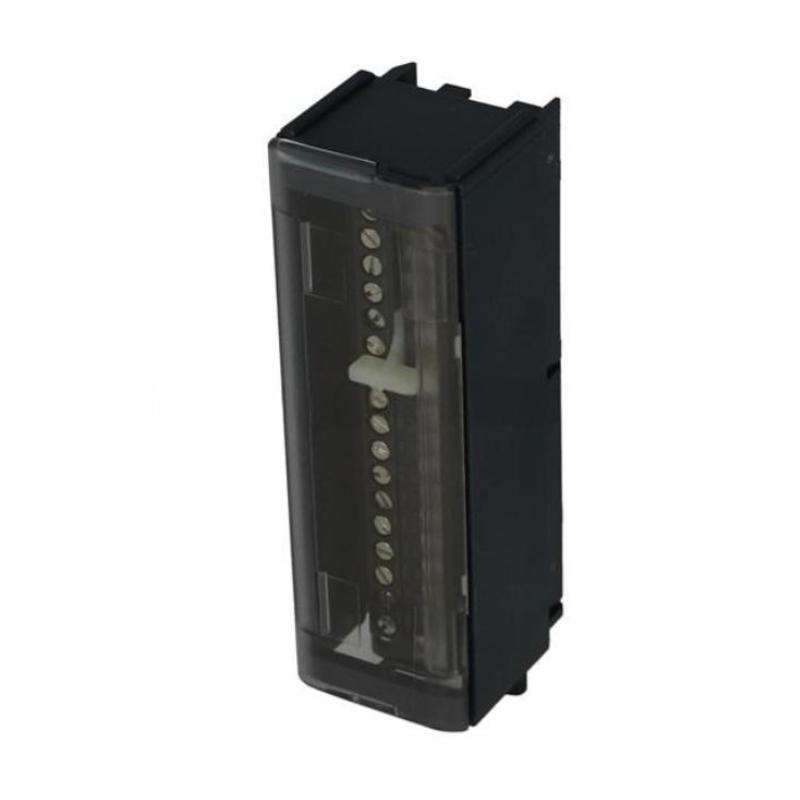
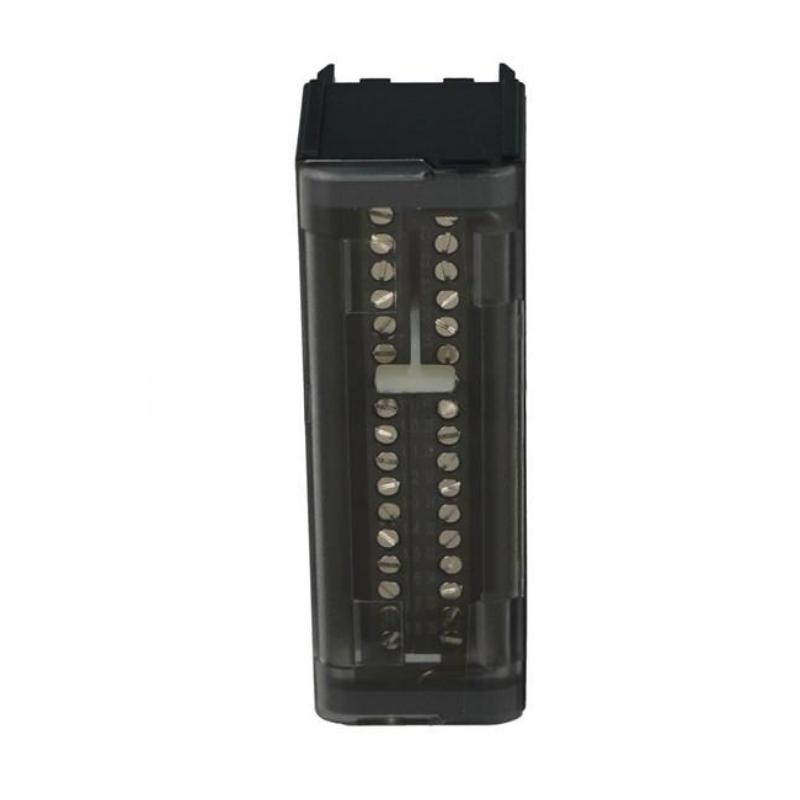
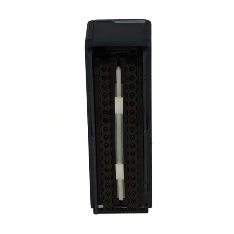
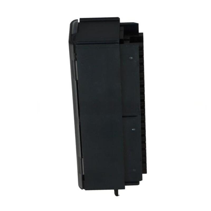
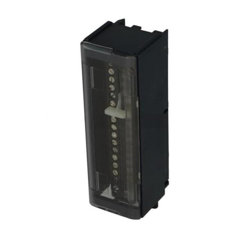
The GE IC694TBB032 Box-Type High-Density Terminal Block is a compact PLC wiring component designed to provide an organized connection point between a compatible industrial automation module and its associated field wiring.
Terminal blocks are an important part of PLC installations because they establish the physical connection between I/O circuits, field devices, control wiring, and the PLC system. A well-installed terminal block helps maintain clear circuit identification, secure electrical connections, and efficient maintenance.
The IC694TBB032 is identified as a Box-Type High-Density Terminal Block, making it suitable for applications where multiple field connections need to be organized within a relatively compact space.
The specified dimensions are 120 × 60 × 40 mm, and the specified weight is 0.14 kg.
Unlike a CPU or I/O module, the terminal block does not execute PLC logic. Its primary role is electrical connection and wiring organization. Consequently, most problems associated with a terminal block involve wiring, loose connections, incorrect terminal assignments, damaged conductors, or compatibility issues.
Product Identification
| Parameter | Specification |
|---|---|
| Manufacturer | GE |
| Series | IC694 |
| Model | IC694TBB032 |
| Product Type | Box-Type High-Density Terminal Block |
| Main Function | Field Wiring Connection |
| Application | PLC / Industrial Automation |
| Dimensions | 120 × 60 × 40 mm |
| Weight | 0.14 kg |
| Installation | Control Cabinet / PLC System |
| System Role | Electrical Interface and Wiring Distribution |
| Construction Type | Box-Type |
| Design Characteristic | High-Density Terminal Arrangement |
Technical Specifications
| Technical Item | Specification |
|---|---|
| Manufacturer | GE |
| Model | IC694TBB032 |
| Product Category | High-Density Terminal Block |
| Terminal Style | Box-Type |
| Main Function | Field Wiring Interface |
| Dimensions | 120 × 60 × 40 mm |
| Weight | 0.14 kg |
| Installation Environment | Industrial Control Cabinet |
| Application | PLC and Automation Wiring |
| Signal Function | Depends on Connected Module |
| Maintenance | Terminal, Wiring, and Connection Inspection |
| Mounting | Compatible System Installation |
The exact terminal count, terminal numbering, conductor-size range, electrical ratings, mounting arrangement, and module compatibility should be confirmed against the applicable system configuration before installation.
What Is the GE IC694TBB032?
The IC694TBB032 is a box-type high-density terminal block used to organize and terminate electrical connections within an industrial automation system.
A typical wiring architecture can be represented as:
Field Device
↓
Field Cable
↓
IC694TBB032 Terminal Block
↓
PLC / I/O Module
↓
CPU
↓
Control Program
The terminal block therefore acts as an electrical connection point between field wiring and the control system.
Main Functions
Field Wiring Termination
The terminal block provides an organized location for connecting field conductors.
Typical field circuits may include:
- Sensors
- Pushbuttons
- Limit switches
- Solenoid circuits
- Relay circuits
- Control signals
- Auxiliary devices
The actual circuit type depends on the connected PLC module and application.
Wiring Organization
A high-density terminal block can help organize multiple circuits in a compact cabinet area.
Good organization allows technicians to identify:
- Signal destination
- Circuit number
- Terminal number
- Device name
- PLC address
- Cable identification
This becomes especially important when troubleshooting a large control cabinet.
Electrical Interface
The IC694TBB032 itself does not determine the function of every connected circuit.
Its electrical purpose depends on:
- Connected PLC module
- Terminal assignment
- Field-device type
- Control voltage
- Circuit architecture
Therefore, the terminal block should always be installed according to the correct wiring diagram.
Installation Guide
1. Verify the Terminal Block Model
Confirm the identification:
GE IC694TBB032
Check the label before installation.
Do not substitute another terminal block simply because it appears physically similar.
2. Inspect the Terminal Block
Before installation, inspect for:
- Cracked housing
- Broken terminal components
- Damaged connection points
- Bent or damaged contacts
- Corrosion
- Contamination
- Signs of overheating
A damaged terminal block should be replaced rather than forced into service.
3. Confirm Compatibility
Before installation, verify:
- Associated PLC module
- Terminal assignment
- Mechanical compatibility
- Electrical rating
- Wiring arrangement
- Cabinet mounting requirements
This is especially important when replacing an existing terminal block.
4. Check Physical Dimensions
The specified dimensions are:
120 × 60 × 40 mm
Provide adequate space for:
- Terminal access
- Cable routing
- Wire bending
- Labels
- Maintenance
- Adjacent equipment
Do not install the terminal block where connected wires will be sharply bent or mechanically strained.
5. Check Weight
The specified weight is:
0.14 kg
Although lightweight, the total mechanical load can increase considerably when many field cables are connected.
Cable support should therefore be provided where necessary.
6. Isolate Power
Before wiring or replacing the terminal block:
- Stop the machine safely.
- Shut down the control system.
- Isolate applicable electrical power.
- Apply lockout/tagout procedures.
- Verify absence of hazardous voltage.
- Discharge stored energy where applicable.
- Follow plant electrical-safety procedures.
Never assume a terminal is safe because the PLC program is stopped.
7. Install the Terminal Block
Position the IC694TBB032 correctly within the designated installation location.
Make sure the block is:
- Properly aligned
- Mechanically secure
- Correctly positioned
- Accessible for wiring
Avoid excessive mechanical force.
8. Prepare the Wires
Before terminating wires:
- Verify wire identification
- Check conductor condition
- Strip insulation correctly
- Avoid damaging conductor strands
- Use appropriate wire-end preparation
- Maintain clear labeling
Damaged or poorly prepared conductors can create intermittent faults.
9. Connect Field Wiring
Connect each conductor according to the approved wiring diagram.
Verify:
- Terminal number
- Signal name
- Voltage
- Polarity where applicable
- Common/reference
- Device destination
Do not rely on memory when reconnecting a large terminal block.
Terminal Labeling
A clear labeling system can significantly reduce maintenance time.
A useful identification method may include:
Terminal → PLC Address → Device → Cable Number
For example:
| Identification | Example |
|---|---|
| Terminal | TB-01 |
| PLC Address | Input Point |
| Field Device | Proximity Sensor |
| Cable | C-101 |
The actual identifiers should follow the plant’s documentation system.
Wiring Best Practices
Avoid Excessive Wire Length
Excess wire should be routed neatly rather than packed tightly around the terminal block.
Avoid Mechanical Stress
Do not allow heavy cables to pull directly on terminal connections.
Use cable support where necessary.
Maintain Separation
Where practical, separate:
- Low-level control signals
- High-current circuits
- Motor power cables
- VFD wiring
- Communication cables
This helps reduce interference and improves cabinet organization.
Commissioning Procedure
Step 1 – Mechanical Check
Confirm:
- Terminal block secure
- Housing undamaged
- Connections accessible
- Cable routing acceptable
Step 2 – Wiring Check
Verify every connection against the wiring diagram.
Check:
- Terminal numbers
- Cable identification
- Polarity
- Common connections
- Signal destinations
Step 3 – Continuity Check
Where appropriate and with the circuit safely isolated, verify continuity of critical conductors.
Look for:
- Open circuits
- Short circuits
- Incorrect cross-connections
Step 4 – Power Verification
Restore power according to the approved startup procedure.
Verify that the connected circuit receives the expected electrical conditions.
Step 5 – I/O Verification
If the terminal block connects to PLC I/O, activate representative field devices and confirm that the corresponding PLC signals change correctly.
Step 6 – Functional Test
Run the equipment through the required operating sequence.
Verify:
- Inputs
- Outputs
- Interlocks
- Alarms
- Field-device responses
Troubleshooting Guide
Fault 1 – Field Signal Does Not Reach the PLC
Possible Causes
- Loose terminal
- Incorrect terminal assignment
- Broken wire
- Incorrect cable
- Incorrect module connection
- Damaged terminal
Diagnostic Path
Field Device → Cable → IC694TBB032 → PLC Module
Check each point sequentially.
Fault 2 – Intermittent Signal
Intermittent signals are often associated with:
- Loose connections
- Poor wire termination
- Vibration
- Corrosion
- Damaged conductors
- Mechanical cable stress
Inspect the terminal connection while following safe maintenance procedures.
Fault 3 – Multiple Signals Fail
If multiple circuits fail simultaneously, investigate shared connections first.
Possible causes include:
- Common terminal connection
- Shared power supply
- Connector problem
- Associated PLC module
- Wiring harness issue
A terminal block problem can affect multiple field circuits at once.
Fault 4 – Incorrect Signal Appears at the PLC
Possible causes include:
- Cross-wired terminals
- Incorrect cable identification
- Wrong terminal assignment
- Incorrect PLC address
- Field-device problem
Compare the physical wiring with the engineering drawings.
Fault 5 – Terminal Overheats
Possible Causes
- Excessive current
- Loose connection
- Incorrect conductor size
- Poor termination
- Damaged terminal
- Overloaded circuit
A hot terminal should not be ignored.
Immediately investigate the electrical cause using appropriate safety procedures.
Fault 6 – Terminal Connection Becomes Loose
Possible causes include:
- Vibration
- Improper tightening
- Mechanical cable strain
- Repeated maintenance
- Incorrect conductor preparation
Inspect the entire connection rather than tightening blindly.
Fault 7 – Corrosion Appears
Possible causes include:
- High humidity
- Chemical exposure
- Condensation
- Poor cabinet sealing
- Environmental contamination
Investigate the environmental cause as well as the terminal itself.
Fault 8 – PLC Input Remains OFF
Check:
- Field sensor
- Sensor power
- Cable continuity
- Terminal connection
- Associated I/O module
- PLC input configuration
The terminal block is only one part of the signal path.
Fault 9 – PLC Output Does Not Reach the Field Device
Trace:
PLC Output → Module → Terminal Block → Field Wiring → Load
Check each point individually.
Fault 10 – Wiring Error After Maintenance
If problems appear immediately after maintenance, compare the current wiring against the previous documented configuration.
Common causes include:
- Swapped conductors
- Wrong terminal
- Incorrect common connection
- Misidentified cable
- Incomplete reconnection
Fault Diagnosis Flow
A practical diagnostic sequence is:
Field Device
↓
Field Cable
↓
IC694TBB032
↓
PLC I/O Module
↓
PLC CPU
↓
Control Program
For output circuits, follow the path in reverse:
PLC Program
↓
CPU
↓
I/O Module
↓
IC694TBB032
↓
Field Device
This method helps isolate wiring faults from PLC hardware or programming faults.
Preventive Maintenance
Terminal Inspection
Inspect periodically for:
- Loose connections
- Corrosion
- Discoloration
- Cracks
- Damaged terminals
- Cable strain
Cable Inspection
Check:
- Insulation condition
- Conductor identification
- Mechanical damage
- Cable routing
- Bending radius
- Strain relief
Cabinet Inspection
Maintain:
- Cleanliness
- Appropriate temperature
- Low humidity
- Adequate ventilation
- Proper cable organization
Connection Verification
During scheduled maintenance, inspect critical connections according to the plant’s maintenance procedure.
Avoid unnecessary disturbance of correctly installed terminals.
Documentation Maintenance
Keep updated:
- Wiring diagrams
- Terminal schedules
- Cable lists
- I/O assignments
- Panel drawings
- Modification records
Accurate documentation is particularly valuable when troubleshooting high-density wiring.
Preventive Maintenance Table
| Maintenance Area | Recommended Action |
|---|---|
| Terminal Housing | Inspect for damage |
| Connections | Check condition and security |
| Field Wiring | Inspect insulation and conductors |
| Labels | Verify readability |
| Cable Routing | Check for strain and interference |
| Cabinet | Keep clean and dry |
| Corrosion | Inspect for environmental damage |
| Heat | Check for abnormal discoloration |
| Documentation | Keep wiring diagrams current |
| Associated I/O | Verify signal operation |
Industrial Applications
PLC Control Panels
The IC694TBB032 can be used as part of a PLC cabinet where multiple field connections must be organized and terminated.
Machine Automation
Machine control panels can contain numerous:
- Sensors
- Switches
- Actuators
- Relays
- Solenoids
A high-density terminal arrangement helps organize these connections.
Production Lines
Production equipment may have extensive field wiring between:
- Machine sensors
- Control cabinets
- PLC modules
- Actuators
Terminal blocks provide an accessible maintenance interface.
Process Equipment
Industrial process systems often require organized wiring for:
- Valve commands
- Status signals
- Interlocks
- Alarm circuits
- Equipment feedback
The terminal block can form part of the physical interface between these circuits and the PLC system.
Remote Equipment Connections
When field devices are located away from the main PLC rack, terminal blocks can provide a convenient transition point for cable organization and maintenance.
High-Density Wiring Applications
The box-type high-density design can be useful where cabinet space is limited and multiple circuits must be arranged efficiently.
The benefits become more apparent as the number of field connections increases.
Terminal Block vs. Standard Wiring Junction
| Feature | High-Density Terminal Block | Basic Junction Connection |
|---|---|---|
| Wiring Organization | High | Variable |
| Maintenance Access | Good | Depends on Design |
| Circuit Identification | Easy to Implement | Often Less Structured |
| Cabinet Space | Compact | Application Dependent |
| PLC Integration | Suitable | Depends on Architecture |
| Documentation | Terminal-Based | Often Cable-Based |
Replacement Procedure
1. Record the Existing Wiring
Before removal, document:
- Terminal numbers
- Cable numbers
- Device names
- Signal types
- PLC addresses
- Common connections
2. Photograph the Installation
Where permitted by plant procedures, photographs can help confirm the original wiring arrangement.
However, photographs should supplement—not replace—formal wiring documentation.
3. Isolate Power
Stop the equipment and isolate applicable electrical energy.
Verify that the terminal circuits are safe to handle.
4. Label All Wires
Clearly identify every conductor before disconnecting it.
This is especially important for high-density terminal blocks.
5. Remove the Existing Terminal Block
Disconnect the field wiring and release the mounting arrangement.
Handle the block carefully to avoid damaging adjacent wiring.
6. Inspect Associated Equipment
Check:
- PLC connector
- Wiring harness
- Adjacent modules
- Cabinet mounting
- Cable condition
7. Install the Replacement
Install the replacement terminal block in the correct position.
Verify mechanical security.
8. Reconnect Wires
Reconnect each conductor according to the documented terminal schedule.
Double-check the complete terminal list before energizing.
9. Perform Electrical Checks
Where appropriate, verify:
- Continuity
- Isolation
- Correct polarity
- Correct circuit routing
- Absence of unintended shorts
10. Commission the System
Test:
- Inputs
- Outputs
- Field devices
- Interlocks
- Alarms
- Machine sequence
Replacement Considerations
| Parameter | Specification / Check |
|---|---|
| Manufacturer | GE |
| Model | IC694TBB032 |
| Product Type | Box-Type High-Density Terminal Block |
| Dimensions | 120 × 60 × 40 mm |
| Weight | 0.14 kg |
| Mechanical Compatibility | Confirm |
| Associated Module | Confirm |
| Terminal Assignment | Confirm |
| Electrical Rating | Confirm |
| Conductor Size | Confirm |
| Mounting Arrangement | Confirm |
| Wiring Configuration | Confirm |
The replacement terminal block should be selected according to mechanical, electrical, and system compatibility rather than dimensions alone.
Key Advantages
- Compact terminal-block design
- High-density wiring arrangement
- Provides organized field connections
- Simplifies circuit identification
- Supports PLC control-panel wiring
- Facilitates maintenance and troubleshooting
- Helps separate field wiring from PLC module connections
- Suitable for industrial automation cabinets
- Specified dimensions of 120 × 60 × 40 mm
- Specified weight of 0.14 kg
Technical FAQs
What is the GE IC694TBB032?
The GE IC694TBB032 is identified as a Box-Type High-Density Terminal Block used for organizing and terminating electrical connections in a compatible industrial automation system.
What are the dimensions of the IC694TBB032?
The specified dimensions are 120 × 60 × 40 mm.
What is the weight of the IC694TBB032?
The specified weight is 0.14 kg.
What is the purpose of a PLC terminal block?
A terminal block provides a physical connection point between field wiring and PLC or I/O system connections.
Does the IC694TBB032 execute PLC logic?
No. A terminal block is a passive wiring component. PLC processing is performed by the CPU module.
Why is a high-density terminal block useful?
It allows multiple circuits to be organized within a relatively compact physical area, which can be valuable in control cabinets with limited space.
Why might a field signal fail at the PLC?
Possible causes include a broken cable, loose terminal, incorrect wiring, damaged terminal, failed field device, or a problem with the associated I/O module.
Why do intermittent faults frequently involve terminal connections?
Vibration, mechanical strain, corrosion, poor conductor preparation, or loose connections can cause electrical contact to change intermittently.
What should be checked before replacing the terminal block?
Check the wiring, terminals, field device, associated I/O module, connector, and PLC configuration first.
Can a damaged terminal block cause multiple PLC faults?
Yes. A common connection or multiple damaged terminals can interrupt several field circuits simultaneously.
Why is terminal labeling important?
Clear labels allow technicians to identify circuits quickly and reduce the risk of incorrect reconnection during maintenance.
What should be done if a terminal becomes unusually hot?
The circuit should be safely isolated and investigated for excessive current, loose connections, incorrect conductor sizing, poor termination, or component damage.
Conclusion
The GE IC694TBB032 Box-Type High-Density Terminal Block is a compact wiring component intended to organize and terminate field connections within an industrial PLC or automation control system. Its specified dimensions are 120 × 60 × 40 mm, and its specified weight is 0.14 kg.
Although a terminal block does not perform PLC processing itself, its reliability directly affects the quality of the electrical connection between field equipment and the control system. A loose terminal, damaged conductor, incorrect connection, or poor cable arrangement can result in intermittent signals, missing I/O, unexpected machine behavior, and difficult-to-diagnose faults.
Installation should therefore focus on correct terminal identification, secure mechanical mounting, proper conductor preparation, accurate wiring, cable support, and appropriate separation of signal and power wiring. During troubleshooting, technicians should trace the complete signal path from field device → cable → IC694TBB032 → I/O module → PLC CPU rather than immediately replacing PLC hardware.
For replacement and maintenance, accurate terminal schedules, cable labels, wiring diagrams, and documented I/O assignments are essential. With correct installation and periodic inspection, the IC694TBB032 can provide a practical and organized wiring interface for demanding industrial automation control panels.