

ProductPRODUCT
Featured products



Contact Us
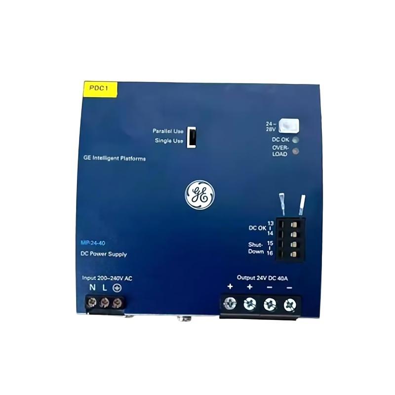
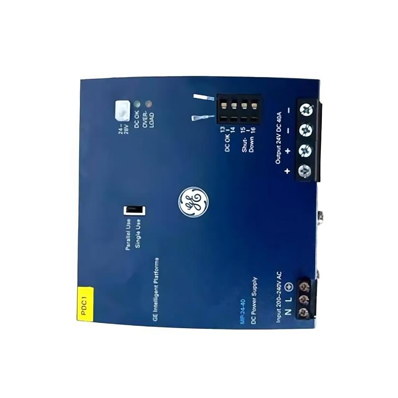
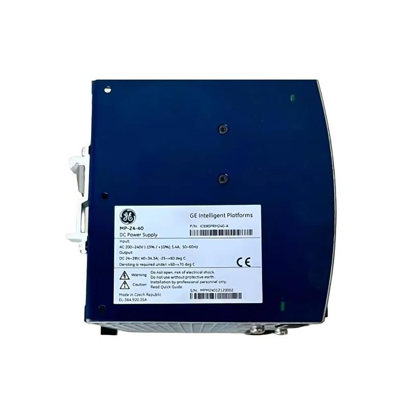
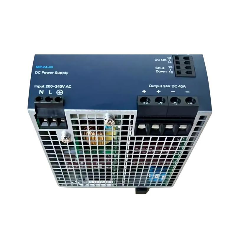
- GE
- IC690PRM120
- Power Supply
- USA
- 200 × 50 × 120 mm
- 1.36 kg
- Xiamen, China
- New & In Stock
- T/T, PayPal, Western Union
- 1 Year
- 1-3 Working Days
- DHL, UPS, TNT, FedEx and EMS.
- 24-Hour Service
- COO
- 69
Our advantage

Global Logistics
We have a 10-year logistics and express cooperation agreement, so our products can be shipped to any place in the world.

Brand new and original
Our products are imported in bulk from the place of origin. Because of the cooperative relationship, our products are all original and 100% new.

24-hour service
We provide 7*24 hours service to our customers. We will be there whenever you need us.

Price advantage
All our products are priced very favorably because we have our own warehouse and supply.
| Company Information | |||
| [email protected] | |||
| Mobile | +8615980777398 | ||
| +8615980777398 | |||
| 15980777398 |
Product Overview
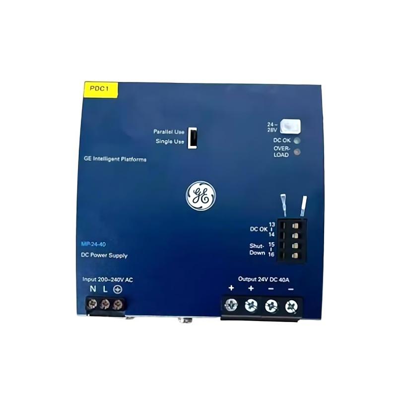
The GE IC690PRM120 Power Supply is an industrial automation power-supply component intended for use within control and automation systems. As part of an industrial control architecture, the power supply provides the electrical power required by connected control equipment and helps maintain stable operation of the automation system.
In PLC and industrial control installations, reliable power conversion and distribution are essential. A power-supply problem can affect controllers, I/O modules, communication equipment, sensors, and field devices simultaneously. For this reason, the IC690PRM120 should be installed with careful attention to input power, grounding, wiring, environmental conditions, cabinet ventilation, and load requirements.
The model specified here has dimensions of 200 × 50 × 120 mm and a weight of 1.36 kg.
This article provides practical guidance for installation, commissioning, preventive maintenance, fault diagnosis, and system integration of the GE IC690PRM120.
Product Identification
| Parameter | Specification |
|---|---|
| Manufacturer | GE |
| Product Series | IC690 |
| Model | IC690PRM120 |
| Product Type | Industrial Power Supply |
| Main Function | Control System Power Supply |
| Application | Industrial Automation |
| Dimensions | 200 × 50 × 120 mm |
| Weight | 1.36 kg |
| Installation | Industrial Control Cabinet |
| System Type | PLC / Automation Control System |
| Typical Use | Control Power Distribution |
| Maintenance | Periodic Electrical and Thermal Inspection |
Technical Specifications
| Technical Item | IC690PRM120 |
|---|---|
| Manufacturer | GE |
| Model | IC690PRM120 |
| Product Category | Power Supply |
| Application | Industrial Automation |
| Dimensions | 200 × 50 × 120 mm |
| Weight | 1.36 kg |
| Installation Environment | Control Cabinet |
| Function | Provides electrical power for control equipment |
| Integration | PLC / I/O / Control System |
| Maintenance Requirement | Electrical, wiring, and thermal inspection |
The exact electrical input, output, current capacity, protection characteristics, and system compatibility should be verified against the specific equipment documentation and the actual installation requirements before commissioning.
Role of the IC690PRM120 in an Automation System
A typical industrial control system can be represented as:
Incoming Electrical Supply
↓
Protection / Isolation
↓
IC690PRM120 Power Supply
↓
PLC / Controller
↓
I/O Modules
↓
Sensors and Actuators
↓
Industrial Process
The power supply forms an important part of this architecture because instability in the control-power system can produce symptoms throughout the entire automation installation.
A controller that repeatedly resets, an I/O module that disappears from the network, or communication equipment that intermittently loses connection may all require investigation of the power system.
Power Supply Working Principle
An industrial power supply generally performs several important functions between the incoming electrical source and the control system.
These functions can include:
- Receiving electrical input.
- Converting or conditioning the incoming power.
- Providing suitable power to the control system.
- Maintaining stable operation under normal load.
- Protecting the system against selected abnormal electrical conditions.
- Supporting reliable operation of connected automation equipment.
The exact electrical behavior depends on the design of the IC690PRM120 and the specific system in which it is installed.
For replacement applications, technicians should compare the electrical requirements of the existing installation with the replacement unit before connecting power.
Installation Requirements
1. Confirm the Model
Before installation, verify:
GE IC690PRM120
Check the identification label and compare the replacement unit with the existing system.
Inspect the unit for:
- Cracked housing
- Damaged terminals
- Bent mounting points
- Loose components
- Corrosion
- Moisture
- Burn marks
- Discoloration
- Signs of overheating
Do not install equipment showing physical damage.
2. Verify the Electrical Requirements
Before connecting the IC690PRM120, determine the actual electrical requirements of the control system.
Verify:
- Input voltage
- Input frequency
- Output voltage
- Output current
- Connected load
- Protection requirements
- Grounding requirements
- Control-system power consumption
The replacement power supply should not be connected simply because its physical dimensions match the original unit.
Electrical compatibility must be confirmed first.
3. Calculate the Control-System Load
Determine the total power consumption of all connected devices.
Consider:
- PLC CPU
- I/O modules
- Communication modules
- Operator interfaces
- Sensors
- Relays
- Contactors
- Solenoid valves
- Network equipment
- Other control devices
A suitable engineering margin should be maintained rather than operating the power supply continuously at its maximum capacity.
4. Cabinet Space
The specified dimensions are:
200 × 50 × 120 mm
When designing the cabinet, do not reserve only the exact physical footprint.
Additional space may be required for:
- Power cables
- Terminal access
- Ventilation
- Cable bending
- Inspection
- Maintenance
- Adjacent equipment
Avoid placing heat-sensitive components immediately beside the power supply.
5. Mounting
The specified weight is:
1.36 kg
The mounting structure should securely support the unit.
Verify:
- Mounting hardware
- Panel rigidity
- Mechanical stability
- Correct orientation
- Vibration
- Cable support
The power supply should not be allowed to move or vibrate excessively during machine operation.
6. Environmental Conditions
Industrial control cabinets can expose electronic equipment to dust, heat, vibration, and electrical interference.
Protect the IC690PRM120 from:
- Water
- Condensation
- Excessive humidity
- Conductive dust
- Oil contamination
- Corrosive substances
- Excessive heat
- Excessive vibration
Cabinet ventilation should be sufficient to prevent excessive temperature buildup.
Electrical Wiring
Power Isolation
Before performing electrical work:
- Disconnect the incoming power.
- Apply lockout/tagout procedures.
- Verify the absence of hazardous voltage.
- Check for stored electrical energy.
- Confirm the circuit is isolated.
- Use appropriate electrical PPE.
Never perform wiring work on energized terminals.
Input Wiring
Connect the incoming supply according to the approved electrical schematic.
Before energizing, verify:
- Correct input terminals
- Correct voltage
- Correct polarity where applicable
- Protective devices
- Grounding
- Cable size
- Terminal tightness
- Insulation
Incorrect input wiring can damage the power supply and connected equipment.
Output Wiring
The output circuit should be connected according to the system’s electrical design.
Before connection, determine:
- Connected load
- Output voltage requirement
- Current demand
- Cable size
- Protection
- Polarity where applicable
- Grounding arrangement
Avoid connecting loads that exceed the designed capacity of the power supply.
Grounding
A proper grounding arrangement is important for industrial automation equipment.
Verify:
- Protective earth connection
- Cabinet grounding
- Ground conductor integrity
- Terminal tightness
- Ground continuity
Poor grounding can contribute to:
- Electrical noise
- Communication problems
- Unstable control signals
- Unexpected resets
- Safety problems
Separation of Wiring
Where practical, separate high-current or high-noise wiring from sensitive control wiring.
Avoid unnecessarily routing power cables together with:
- Analog signal cables
- Communication cables
- Sensor wiring
- Encoder wiring
- Low-level control signals
Good cabinet wiring practices can reduce electrical interference.
Commissioning Procedure
Pre-Power Inspection
Before applying power:
- Verify the IC690PRM120 model.
- Confirm input requirements.
- Verify output requirements.
- Inspect power wiring.
- Check grounding.
- Verify protective devices.
- Check terminal tightness.
- Confirm the connected load.
- Inspect cabinet ventilation.
- Check for accidental short circuits.
Initial Energization
Apply power under controlled conditions.
Observe:
- Power-supply status
- Output condition
- Controller status
- I/O module operation
- Communication equipment
- Abnormal noise
- Odor
- Excessive heat
If abnormal behavior appears immediately after energization, disconnect power and begin troubleshooting.
Verify Output Stability
Measure the output under appropriate operating conditions.
Compare the measured value with the required system voltage.
A power supply may appear normal without load but become unstable when the complete control system is connected.
Therefore, testing should include the actual operating load whenever practical.
Verify Connected Equipment
After confirming stable power, check:
PLC
Verify that the controller powers up normally.
I/O Modules
Check that all expected modules are recognized.
Communication Equipment
Verify that network devices remain online.
HMI
Confirm normal communication and display operation.
Field Devices
Verify that sensors and actuators receive the expected control power.
Troubleshooting Guide
Fault 1 – Power Supply Does Not Start
Possible Causes
- No input voltage
- Incorrect wiring
- Open circuit protection
- Incorrect input conditions
- Internal power-supply fault
Diagnostic Procedure
Check:
- Incoming voltage
- Protective devices
- Input wiring
- Grounding
- Terminal connections
- Power-supply condition
Fault 2 – Output Voltage Is Missing
Possible Causes
- Input power problem
- Output overload
- Short circuit
- Incorrect wiring
- Internal failure
- Protection function activated
Corrective Action
Disconnect the load in a controlled manner and verify whether the output condition changes.
Then check the downstream wiring and connected equipment.
Fault 3 – PLC Repeatedly Resets
A controller reset does not necessarily mean the PLC itself is defective.
Possible causes include:
- Unstable power supply
- Excessive load
- Loose power connection
- Voltage drop
- Short circuit
- Electrical interference
- Overheated power supply
Diagnostic Procedure
Monitor the control-system power while the PLC is operating.
Inspect:
- Input power
- Output voltage
- Wiring
- Terminal connections
- Load changes
- Cabinet temperature
Fault 4 – I/O Modules Intermittently Disconnect
Possible Causes
- Power instability
- Loose wiring
- Insufficient control voltage
- Communication problem
- Grounding issue
- Excessive electrical noise
Start troubleshooting at the power supply before replacing I/O modules unnecessarily.
Fault 5 – Power Supply Overheats
Possible Causes
- Excessive load
- Poor cabinet ventilation
- High ambient temperature
- Restricted airflow
- Dust contamination
- Nearby heat-producing equipment
Corrective Action
Check the total connected load and cabinet thermal conditions.
Ensure that ventilation paths are not blocked.
Fault 6 – Output Voltage Drops Under Load
Possible Causes
- Excessive load
- Short circuit
- Undersized wiring
- Poor terminal connection
- Power-supply degradation
- Excessive temperature
Diagnostic Procedure
Measure the output voltage:
- Without load, where safe and appropriate.
- Under normal load.
- During peak load conditions.
A significant change under load can indicate a power-capacity or downstream problem.
Fault 7 – Fuse or Circuit Protection Repeatedly Trips
Possible Causes
- Short circuit
- Excessive load
- Incorrect protection selection
- Wiring fault
- Failed downstream device
Do not simply replace the protective device repeatedly.
Locate and correct the underlying electrical problem first.
Fault 8 – Control System Becomes Unstable After Adding a New Module
Possible Causes
- Increased power demand
- Insufficient supply capacity
- Incorrect wiring
- Short circuit
- New module malfunction
- Power-distribution problem
Calculate the revised total load after adding the module.
Fault 9 – Communication Errors Occur After Startup
Possible Causes
- Unstable control power
- Grounding problems
- Electrical interference
- Loose communication wiring
- Network equipment power interruption
Communication problems should be investigated together with the power system, especially when multiple devices experience intermittent failures simultaneously.
Fault 10 – Power Supply Produces Abnormal Noise
Possible Causes
- Mechanical vibration
- Electrical stress
- Overload
- Cooling-system issue
- Internal component deterioration
Disconnect the equipment if there is unusual noise accompanied by overheating, burning odor, smoke, or other abnormal behavior.
Fault Diagnosis Strategy
A reliable troubleshooting sequence is:
Incoming Power
↓
Circuit Protection
↓
IC690PRM120 Input
↓
IC690PRM120 Output
↓
Power Distribution
↓
PLC / Controller
↓
I/O Modules
↓
Communication Equipment
↓
Field Devices
This approach helps determine whether the fault originates at the power source, power supply, distribution wiring, controller, I/O system, communication network, or field equipment.
Preventive Maintenance
Electrical Inspection
Periodically inspect:
- Input terminals
- Output terminals
- Ground connections
- Cable insulation
- Terminal tightness
- Signs of overheating
- Discoloration
- Corrosion
Thermal Inspection
Monitor:
- Power-supply temperature
- Cabinet temperature
- Airflow
- Ventilation openings
- Nearby heat sources
An increase in operating temperature can be an early indication of excessive loading or deteriorating cooling conditions.
Load Inspection
Periodically review the connected load.
Check whether additional equipment has been added to the control system.
A power supply that operated correctly when originally commissioned may become overloaded after system expansion.
Preventive Maintenance Table
| Maintenance Area | Inspection / Action |
|---|---|
| Input Voltage | Verify stable supply |
| Output Voltage | Check under normal operating load |
| Input Terminals | Inspect tightness |
| Output Terminals | Inspect connection integrity |
| Grounding | Verify continuity |
| Cable Insulation | Inspect for deterioration |
| Cabinet Ventilation | Keep airflow unobstructed |
| Dust | Remove accumulated contamination |
| Temperature | Monitor operating conditions |
| Connected Load | Review periodically |
| Protective Devices | Inspect condition |
| PLC Operation | Check for unexpected resets |
| I/O System | Monitor intermittent faults |
| Communication | Check for power-related interruptions |
Common Installation Mistakes
Incorrect Input Voltage
Applying an incorrect input condition can cause immediate equipment failure.
Always verify the electrical design before energization.
Overloading the Power Supply
Adding more PLC modules, communication equipment, sensors, relays, or other loads without recalculating the total power demand can create instability.
Poor Ventilation
Even when the electrical load is within the expected range, excessive cabinet temperature can reduce reliability.
Loose Terminals
Loose electrical connections can produce:
- Voltage drops
- Heating
- Intermittent operation
- Arcing
- Equipment damage
Poor Grounding
Grounding problems can contribute to noise, communication errors, and unstable control operation.
Inadequate Cable Sizing
Undersized wiring can produce voltage drops and excessive heating.
Replacing Modules Before Checking Power
If several automation devices fail simultaneously or intermittently, inspect the control-power system before replacing multiple PLC or I/O modules.
PLC System Integration
The IC690PRM120 can form part of the power architecture supporting an industrial automation system.
A simplified structure is:
AC Input
↓
Protection
↓
IC690PRM120
↓
PLC Controller
↓
I/O System
↓
Sensors / Actuators
↓
Industrial Process
Reliable control power is particularly important when multiple automation modules depend on the same power source.
A power disturbance can potentially affect several devices simultaneously, making power-supply diagnostics an important first step in many system-level troubleshooting situations.
Compatible System Components
Depending on the specific control architecture, an industrial power supply may support a system containing:
- PLC CPUs
- I/O modules
- Communication modules
- Remote I/O
- HMIs
- Industrial switches
- Relays
- Sensors
- Actuators
- Solenoid valves
- Control contactors
- Instrumentation equipment
Actual compatibility depends on the electrical specifications and architecture of the complete system.
Replacement Considerations
When replacing an IC690PRM120, do not compare only the model number.
Verify:
1. Physical Compatibility
Confirm:
- Dimensions
- Mounting arrangement
- Cable access
- Cabinet space
2. Electrical Compatibility
Confirm:
- Input voltage
- Output voltage
- Current capacity
- Frequency
- Protection requirements
3. Load Compatibility
Calculate the complete downstream load.
4. Environmental Compatibility
Verify:
- Ambient temperature
- Humidity
- Vibration
- Dust
- Cabinet ventilation
5. System Compatibility
Confirm that the power supply can properly support the controller, I/O modules, communication equipment, and other connected loads.
Key Advantages
- Designed for industrial automation applications
- Provides control-system power
- Compact physical design
- Dimensions of 200 × 50 × 120 mm
- Weight of 1.36 kg
- Suitable for control cabinet installation
- Can support PLC-based architectures
- Can support I/O systems
- Can support industrial communication equipment
- Suitable for centralized control-power applications
- Can be incorporated into industrial automation systems
- Straightforward cabinet integration
- Suitable for preventive maintenance and condition monitoring
Technical FAQs
What is the GE IC690PRM120?
The GE IC690PRM120 is an industrial automation power-supply component intended to provide electrical power within a control-system architecture.
What are the dimensions of the IC690PRM120?
The specified dimensions are 200 × 50 × 120 mm.
How much does the IC690PRM120 weigh?
The specified weight is 1.36 kg.
What is the primary purpose of the IC690PRM120?
Its primary role is to provide suitable control power for equipment within an industrial automation system.
Where can the IC690PRM120 be installed?
It is intended for integration into industrial control cabinets and automation-system power architectures.
What should be checked before installing an IC690PRM120?
Verify the model, electrical input and output requirements, connected load, grounding, protective devices, wiring, cabinet space, and environmental conditions.
Why does the PLC repeatedly restart?
Possible causes include unstable control power, excessive load, voltage drop, loose terminals, wiring problems, electrical interference, or an issue with the downstream system.
Why does the output voltage drop?
Possible causes include excessive load, downstream short circuits, poor wiring, loose connections, excessive temperature, or deterioration of the power supply.
Can a power-supply fault cause communication problems?
Yes. If communication equipment loses stable control power, network devices and automation modules may reset or intermittently disconnect.
Why should the total load be calculated before installation?
Because the power supply must provide sufficient capacity for all connected equipment. Adding PLC modules, I/O modules, sensors, relays, or communication devices can increase the total load.
What is the most important maintenance task?
Regularly checking the input and output power conditions, terminal connections, cabinet temperature, ventilation, and connected load can help identify developing problems.
Should the power supply be replaced immediately when an I/O module fails?
Not necessarily. If multiple devices show intermittent or simultaneous problems, first investigate the control-power system, wiring, grounding, and distribution before replacing individual modules.
Conclusion
The GE IC690PRM120 Power Supply is an industrial automation power component intended to provide reliable electrical power within a control-system architecture. Stable control power is fundamental to the operation of PLCs, I/O modules, communication equipment, sensors, relays, and other automation devices.
The specified IC690PRM120 measures 200 × 50 × 120 mm and weighs 1.36 kg, making these dimensions important considerations when planning control-cabinet installation and maintenance access.
Correct installation begins with verification of the electrical requirements and total connected load. The input circuit, output wiring, grounding, protective devices, cabinet ventilation, and mounting arrangement should all be checked before commissioning.
For troubleshooting, technicians should follow a systematic path from the incoming supply to the power supply output and then through the downstream automation system. If multiple devices experience resets, communication interruptions, or intermittent operation, the control-power system should be investigated before assuming that individual PLC or I/O modules have failed.
Regular electrical inspection, thermal monitoring, load review, terminal maintenance, and cabinet cleaning can help maintain stable operation and reduce unexpected automation-system downtime.