

ProductPRODUCT
Featured products



Contact Us
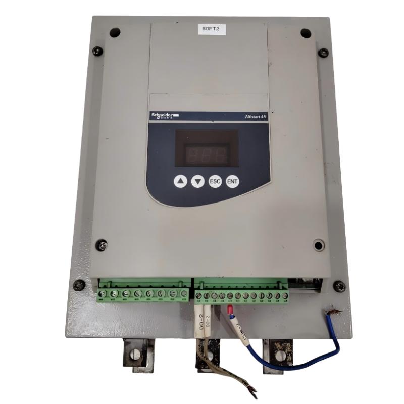
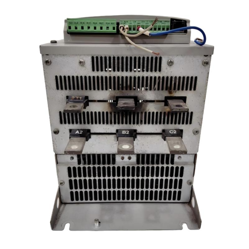
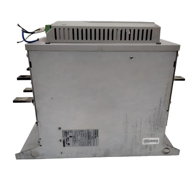
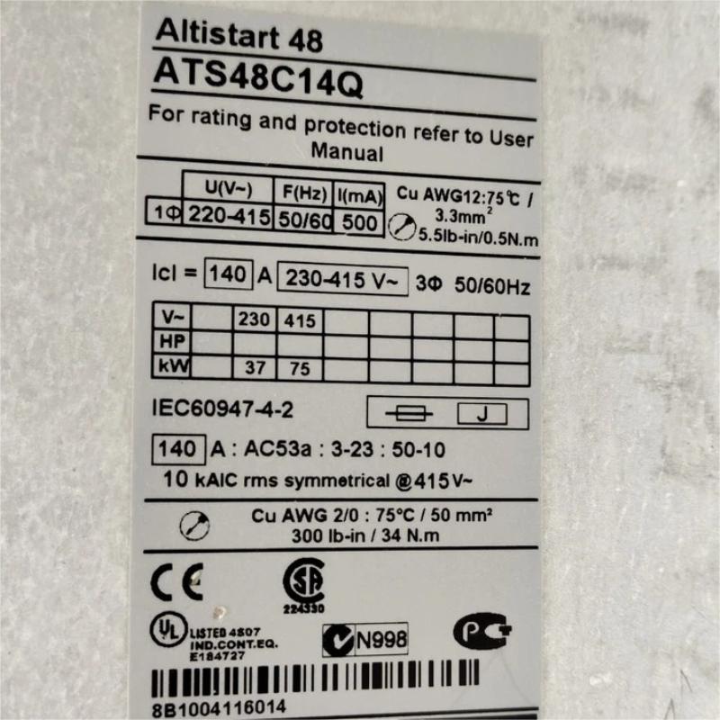
- Schneider
- ATS48C14Q
- Soft Starter
- France
- 340 x 200 x 265 mm
- 12.4 kg
- Xiamen, China
- New & In Stock
- T/T, PayPal, Western Union
- 1 Year
- 1-3 Working Days
- DHL, UPS, TNT, FedEx and EMS.
- 24-Hour Service
- COO
- 51
Our advantage

Global Logistics
We have a 10-year logistics and express cooperation agreement, so our products can be shipped to any place in the world.

Brand new and original
Our products are imported in bulk from the place of origin. Because of the cooperative relationship, our products are all original and 100% new.

24-hour service
We provide 7*24 hours service to our customers. We will be there whenever you need us.

Price advantage
All our products are priced very favorably because we have our own warehouse and supply.
| Company Information | |||
| [email protected] | |||
| Mobile | +8615980777398 | ||
| +8615980777398 | |||
| 15980777398 |
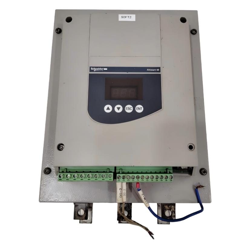
Product Overview
The Schneider ATS48C14Q Soft Starter is an industrial motor-control device from the Altistart 48 series. It is designed for controlled starting and stopping of three-phase asynchronous motors used in industrial machinery and process equipment.
Unlike a conventional direct-on-line starter, a soft starter progressively controls the motor during startup. This helps reduce the mechanical shock and electrical stress associated with starting a motor directly from the supply. The same principle can be applied to controlled stopping when the application requires a smoother deceleration process.
The ATS48C14Q can be considered for industrial equipment such as pumps, fans, compressors, conveyors, blowers, mixers, and other motor-driven machinery. Its communication capability also allows it to be integrated into PLC-based control systems and broader industrial automation architectures.
For the product specified here, the physical dimensions are 340 × 200 × 265 mm, and the supplied weight is 12.4 kg.
Product Identification
| Parameter | Specification |
|---|---|
| Manufacturer | Schneider Electric |
| Product Family | Altistart 48 |
| Model | ATS48C14Q |
| Product Type | Soft Starter |
| Motor Type | Three-Phase Asynchronous Motor |
| Main Function | Controlled Motor Starting and Stopping |
| Communication | Modbus RS-485 |
| Installation | Vertical |
| Dimensions | 340 × 200 × 265 mm |
| Weight | 12.4 kg |
| Typical Applications | Pumps, Fans, Compressors, Conveyors, Mixers |
| Application Area | Industrial Motor Control |
Technical Specifications
| Technical Item | ATS48C14Q |
|---|---|
| Manufacturer | Schneider Electric |
| Series | Altistart 48 |
| Model | ATS48C14Q |
| Product Category | Soft Starter |
| Motor Type | Three-Phase Asynchronous Motor |
| Control Function | Motor Starting / Stopping |
| Communication | Modbus |
| Physical Interface | RS-485 |
| Installation Orientation | Vertical |
| Height | 340 mm |
| Width | 200 mm |
| Depth | 265 mm |
| Weight | 12.4 kg |
| Cooling | Forced Air |
| Typical Loads | Pumps, Fans, Compressors, Conveyors, Mixers |
| Automation Integration | PLC / HMI / DCS |
The ATS48 platform combines motor-starting control with protection and monitoring functions, making the device suitable for integration into industrial motor-control panels.
ATS48C14Q Operating Principle
The basic control architecture is:
Three-Phase AC Supply
↓
ATS48C14Q Soft Starter
↓
Three-Phase Asynchronous Motor
↓
Mechanical Load
When a motor starts directly across the line, it can draw a high starting current and generate a sudden increase in torque.
The ATS48C14Q controls the starting sequence so that the motor can accelerate progressively. This controlled transition can reduce stress on:
- Motor windings
- Couplings
- Gearboxes
- Belts
- Shafts
- Pump assemblies
- Conveyor systems
- Mechanical transmission components
The soft starter can also provide controlled stopping where required by the application.
Major Functions
Controlled Acceleration
The ATS48C14Q provides a controlled motor-starting process rather than an uncontrolled direct connection.
This is particularly useful for machines where sudden torque can produce mechanical shock.
Controlled Deceleration
Controlled stopping can be useful when the process requires the motor to reduce speed gradually.
Typical examples include:
- Pumping systems
- Conveyor systems
- High-inertia fans
- Industrial process equipment
Motor Protection
The ATS48 family incorporates motor and starter protection functions.
Depending on the configuration, the protection system can help identify abnormal conditions involving:
- Motor thermal loading
- Starter temperature
- Phase conditions
- Excessive current
- Abnormal motor operation
Protection settings must be matched to the actual motor and application.
Communication
The ATS48C14Q can participate in an industrial communication architecture through its Modbus communication interface.
A typical system is:
PLC
↓
RS-485 / Modbus
↓
ATS48C14Q
↓
Motor
This allows the automation system to coordinate motor operation and monitor available status and diagnostic information.
Industrial Applications
1. Pumping Equipment
Pump motors often benefit from controlled acceleration and stopping.
Possible applications include:
- Water pumps
- Cooling pumps
- Process pumps
- Transfer pumps
- Industrial circulation systems
- Wastewater equipment
A controlled motor-starting sequence can help reduce sudden changes in the mechanical and fluid system.
2. Fans and Blowers
Large fans and blowers can have significant rotating inertia.
Typical applications include:
- Industrial ventilation
- Exhaust systems
- Cooling equipment
- Dust collection
- Air-handling systems
- Process ventilation
The ATS48C14Q can help provide a more controlled acceleration sequence for suitable motor-driven fan systems.
3. Compressors
Compressor motors can require substantial starting torque.
The ATS48C14Q may be suitable for compressor applications when the motor, load, starting cycle, and soft-starter rating are correctly matched.
Important engineering considerations include:
- Motor rated current
- Compressor loading
- Starting duration
- Starting frequency
- Ambient temperature
- Mechanical resistance
4. Conveyors
Conveyor systems can experience substantial mechanical stress during motor startup.
Controlled acceleration can help reduce:
- Belt shock
- Coupling stress
- Gearbox loading
- Product movement disturbances
- Mechanical vibration
5. Mixers
Mixers can present a demanding starting load, particularly when the process material has high viscosity.
Controlled acceleration can help provide a smoother transition from standstill to operating speed.
6. Industrial Machines
The ATS48C14Q can also be incorporated into industrial machines requiring controlled starting of motors driving:
- Blowers
- Centrifugal equipment
- Material-handling equipment
- Processing machinery
- Rotating production equipment
Installation Guide
Step 1 – Verify Product Identification
Before installation, confirm that the equipment is:
Schneider ATS48C14Q
Inspect the unit for:
- Physical cracks
- Damaged terminals
- Loose components
- Bent mounting points
- Moisture
- Dust contamination
- Signs of impact
- Overheating marks
Do not install a visibly damaged device until it has been inspected.
Step 2 – Verify Motor Information
Obtain the motor nameplate before configuring the ATS48C14Q.
Record:
- Rated voltage
- Rated current
- Rated frequency
- Rated power
- Motor connection
- Rated speed
- Duty classification
- Starting requirements
The soft starter should be matched to the actual motor current and operating duty.
Step 3 – Cabinet Planning
The specified dimensions are:
340 × 200 × 265 mm
The cabinet should provide additional space around the unit.
Consider clearance for:
- Power cables
- Motor cables
- Control wiring
- Communication cables
- Protective devices
- Ventilation
- Cable bending
- Maintenance access
Do not place the device directly against another heat-producing component.
Step 4 – Verify Installation Orientation
Install the ATS48C14Q in the recommended vertical orientation.
Before final mounting, verify:
- Vertical alignment
- Stable mounting
- Ventilation
- Cable access
- Terminal accessibility
- Maintenance clearance
Step 5 – Environmental Preparation
The control cabinet should protect the soft starter from unsuitable environmental conditions.
Avoid exposure to:
- Water
- Condensation
- Excessive dust
- Conductive contamination
- Oil mist
- Corrosive gases
- Excessive vibration
- Excessive heat
The cabinet cooling system should be capable of maintaining suitable operating conditions.
Step 6 – Electrical Isolation
Before wiring the ATS48C14Q:
- Disconnect the incoming supply.
- Apply lockout/tagout procedures.
- Verify the absence of hazardous voltage.
- Isolate the motor.
- Check for stored electrical energy.
- Confirm that the work area is electrically safe.
- Use appropriate electrical PPE.
Never perform power wiring on an energized system.
Step 7 – Mount the Soft Starter
The supplied weight is:
12.4 kg
The mounting structure must therefore provide adequate mechanical support.
Check:
- Mounting hardware
- Panel rigidity
- Vibration resistance
- Vertical orientation
- Cable support
- Ventilation
The soft starter should remain mechanically secure during normal operation.
Step 8 – Connect the Power Circuit
Connect the incoming three-phase supply and motor according to the engineered electrical diagram.
Verify:
- Correct phase wiring
- Cable sizing
- Protective devices
- Grounding
- Terminal connections
- Insulation condition
- Cable routing
Before energizing, inspect every power connection.
Step 9 – Connect Control Wiring
Depending on the system design, control signals may include:
- Start
- Stop
- Reset
- Run indication
- Fault indication
- External interlocks
- PLC commands
- Emergency-stop logic
Keep control wiring organized and separated appropriately from high-current conductors.
Step 10 – Connect Communication
For PLC or supervisory-system integration, connect the communication network according to the system architecture.
Typical communication checks include:
- RS-485 wiring
- Device address
- Communication parameters
- PLC configuration
- Network topology
- Control permissions
A communication fault does not necessarily indicate a defective soft starter.
Step 11 – Configure Motor Parameters
Enter the actual motor data.
Important configuration areas include:
- Motor current
- Starting parameters
- Acceleration time
- Deceleration time
- Current limitation
- Protection settings
- Stop mode
- Command source
Avoid copying configuration values from another machine without checking the motor and load.
Step 12 – Inspect the Mechanical Load
Before starting the motor, verify the connected machine.
Inspect:
- Motor shaft
- Coupling
- Bearings
- Gearbox
- Belts
- Pump
- Fan
- Conveyor
- Mechanical guards
Confirm that the load is free from unexpected mechanical resistance.
Commissioning Procedure
Pre-Startup Checklist
Before applying power:
- Verify motor nameplate information.
- Check power wiring.
- Check control wiring.
- Verify protective grounding.
- Verify circuit protection.
- Check mechanical installation.
- Confirm ventilation.
- Verify soft-starter configuration.
- Test interlocks.
- Check emergency-stop circuitry.
Initial Energization
After completing the inspection:
- Energize the electrical system.
- Observe the ATS48C14Q.
- Check for fault indications.
- Verify the control circuit.
- Check communication status.
- Confirm the intended control mode.
First Motor Start
Start the motor under controlled conditions.
Observe:
- Motor current
- Starting time
- Motor sound
- Vibration
- Starter status
- Mechanical movement
- Process behavior
If abnormal conditions occur, stop the motor and investigate the cause.
Troubleshooting Guide
Fault 1 – ATS48C14Q Does Not Power Up
Possible Causes
- No incoming supply
- Open circuit protection
- Incorrect wiring
- Control-supply problem
- Internal fault
Troubleshooting
Check:
- Incoming voltage
- Protective devices
- Power connections
- Control circuit
- Starter status
Fault 2 – Motor Does Not Start
Possible Causes
- Start command missing
- Incorrect control wiring
- Active interlock
- Incorrect configuration
- Motor problem
- Mechanical obstruction
Diagnostic Procedure
Trace the start command from the PLC, HMI, relay, or external control system.
Then verify the motor circuit and mechanical load.
Fault 3 – Motor Starts Slowly
Possible Causes
- Excessive acceleration time
- Current limitation too restrictive
- Incorrect motor data
- Excessive load
- Mechanical resistance
Corrective Action
Check the motor parameters first.
Then inspect the mechanical load.
Fault 4 – Excessive Current During Starting
Possible Causes
- Acceleration time too short
- Current limitation incorrectly configured
- Heavy load
- Incorrect motor parameters
- Motor fault
Recommended Checks
Compare configured values with the motor nameplate.
Then inspect the connected machinery for abnormal resistance.
Fault 5 – Starter Trips During Acceleration
Possible Causes
- Motor overload
- Phase problem
- Incorrect wiring
- Incorrect configuration
- Mechanical obstruction
- Excessive load
Do not repeatedly reset the starter without identifying the underlying problem.
Fault 6 – ATS48C14Q Overheats
Possible Causes
- Poor cabinet ventilation
- Blocked cooling path
- Excessive ambient temperature
- Excessive starting frequency
- Motor overload
- Dust accumulation
- Cooling-system failure
Corrective Action
Inspect the entire cabinet thermal environment.
Verify airflow and check whether nearby components are generating excessive heat.
Fault 7 – Motor Vibrates
Possible Causes
- Shaft misalignment
- Coupling problem
- Bearing wear
- Mechanical imbalance
- Incorrect acceleration profile
- Mechanical resonance
Inspect the mechanical system as well as the electrical control system.
Fault 8 – Motor Stops Too Quickly
Possible Causes
- Incorrect deceleration settings
- External stop command
- Incorrect control logic
- Incorrect stop configuration
- High-inertia load
Review the programmed stop sequence and external control logic.
Fault 9 – Motor Does Not Stop
Possible Causes
- Stop command missing
- Control wiring problem
- PLC logic problem
- External interlock
- Configuration problem
Trace the stop signal through the complete control chain.
Fault 10 – Modbus Communication Failure
Possible Causes
- Incorrect device address
- Incorrect communication settings
- Damaged RS-485 wiring
- Incorrect PLC configuration
- Network problem
- Communication interface fault
Diagnostic Sequence
First inspect the physical network.
Then check:
- Device address
- Baud rate
- Serial settings
- PLC configuration
- Network connections
Fault 11 – Repeated Overload Trips
Possible Causes
- Excessive load
- Bearing deterioration
- Mechanical obstruction
- Incorrect motor parameters
- Excessive starting frequency
- Incorrect protection settings
- Abnormal process conditions
Repeated trips should be investigated as a system-level problem rather than treated only by resetting the starter.
Fault Diagnosis Flow
Use the following sequence when diagnosing an ATS48C14Q system:
Incoming Supply
↓
Circuit Protection
↓
ATS48C14Q Status
↓
Start / Stop Signals
↓
Communication
↓
Power Wiring
↓
Motor Condition
↓
Mechanical Load
↓
Parameter Configuration
↓
Controlled Restart
This approach helps isolate problems between the power system, soft starter, control system, motor, and mechanical equipment.
Preventive Maintenance
Electrical Maintenance
Inspect:
- Power terminals
- Control terminals
- Ground connections
- Cable insulation
- Signs of overheating
- Loose connections
Cooling Maintenance
Inspect:
- Airflow
- Cooling path
- Cabinet ventilation
- Filters
- Dust accumulation
- Ambient temperature
Keep ventilation openings clear.
Mechanical Maintenance
Check:
- Mounting hardware
- Cable supports
- Shaft alignment
- Couplings
- Bearings
- Gearboxes
- Vibration
Operational Monitoring
Record and monitor:
- Motor current
- Starting duration
- Operating temperature
- Fault history
- Starting frequency
- Motor vibration
- Abnormal noise
Historical operating data can help identify changes before they become major failures.
Preventive Maintenance Table
| Maintenance Item | Recommended Action |
|---|---|
| Power Terminals | Check tightness and overheating |
| Control Terminals | Inspect connection integrity |
| Grounding | Verify continuity |
| RS-485 Network | Inspect communication connections |
| Cooling Path | Clean and inspect |
| Cabinet Ventilation | Maintain unobstructed airflow |
| Filters | Clean or replace as necessary |
| Motor Current | Monitor operating values |
| Fault History | Review periodically |
| Mounting Hardware | Check mechanical stability |
| Cable Insulation | Inspect for deterioration |
| Cabinet Interior | Remove dust and contamination |
| Motor / Load | Inspect alignment and vibration |
Common Installation Mistakes
Incorrect Motor Parameters
Incorrect motor information can result in poor acceleration and unnecessary protection trips.
Insufficient Cabinet Clearance
A cabinet that is too small can restrict airflow and make maintenance difficult.
Poor Ventilation
Heat buildup can negatively affect the soft starter and surrounding equipment.
Loose Electrical Connections
Loose connections can cause heating, voltage drop, intermittent faults, and equipment damage.
Incorrect Control Wiring
A faulty start/stop circuit can prevent normal operation even when the soft starter itself is healthy.
Communication Configuration Errors
Incorrect addressing or serial settings can prevent PLC communication.
Mechanical Problems
A worn bearing, blocked pump, overloaded conveyor, or damaged coupling can appear as a motor-control fault.
Excessive Fault Resets
Repeatedly resetting faults without finding the cause can increase equipment stress and downtime.
PLC and Automation Integration
The ATS48C14Q can be incorporated into a larger industrial control system.
A typical architecture is:
PLC / DCS
↓
Control Commands
↓
ATS48C14Q
↓
Three-Phase Motor
↓
Industrial Machine
↓
Process
The communication interface can provide an additional path for exchanging motor-control and diagnostic information with an automation controller.
Possible automation functions include:
- Remote start
- Remote stop
- Fault monitoring
- Motor status monitoring
- Diagnostic monitoring
- Alarm handling
- Process interlocking
Supporting Components
A complete ATS48C14Q motor-control installation may include:
- Circuit breakers
- Disconnect switches
- Fuses
- Contactors
- Motor protection equipment
- PLC controllers
- HMIs
- Control relays
- RS-485 network components
- Emergency-stop circuits
- Current monitoring
- Motor sensors
- Process sensors
All supporting equipment should be selected according to the actual electrical and mechanical characteristics of the installation.
Related Altistart 48 Models
| Model | Typical Application |
|---|---|
| ATS48C11Q | Higher-current industrial motor applications |
| ATS48C14Q | Larger industrial motor applications |
| ATS48C17Q | Higher-power motor applications |
| ATS48C21Q | Larger motor-control applications |
| ATS48C25Q | Higher-current industrial applications |
| ATS48C32Q | High-power motor applications |
The correct model should be selected according to motor current, supply voltage, starting duty, mechanical load, environmental conditions, and required control performance.
Key Advantages
- Altistart 48 industrial soft-starting platform
- Designed for three-phase asynchronous motors
- Controlled motor acceleration
- Controlled stopping
- Motor protection functions
- Starter protection
- Modbus communication capability
- RS-485 integration
- PLC-compatible automation architecture
- Suitable for pumps and fans
- Suitable for compressors and conveyors
- Suitable for mixers and blowers
- Forced-air cooling
- Vertical installation
- Dimensions: 340 × 200 × 265 mm
- Weight: 12.4 kg
Technical FAQs
What is the Schneider ATS48C14Q?
The Schneider ATS48C14Q is an Altistart 48 industrial soft starter used to control the starting and stopping of three-phase asynchronous motors.
What are the dimensions of the ATS48C14Q?
The specified dimensions are 340 × 200 × 265 mm.
What is the weight of the ATS48C14Q?
The specified weight is 12.4 kg.
What does a soft starter do?
A soft starter controls the electrical conditions during motor starting and stopping, helping reduce sudden electrical and mechanical stress.
What equipment can use the ATS48C14Q?
Suitable applications can include pumps, fans, compressors, conveyors, blowers, mixers, and other industrial motor-driven machines.
Does the ATS48C14Q support communication?
Yes. The ATS48 platform provides Modbus communication capability for integration into industrial automation systems.
Why does the motor fail to start?
Possible causes include a missing start command, incorrect wiring, active interlocks, incorrect parameters, motor faults, or mechanical obstruction.
Why does the ATS48C14Q overheat?
Possible causes include inadequate ventilation, blocked airflow, excessive ambient temperature, excessive starting frequency, motor overload, or contamination.
Why does the starter trip during acceleration?
Possible causes include excessive mechanical load, incorrect motor parameters, phase problems, wiring faults, unsuitable settings, or mechanical resistance.
What should be checked before commissioning?
Verify motor nameplate data, power wiring, control wiring, grounding, protection, cabinet ventilation, communication settings, soft-starter parameters, and mechanical load.
Can the ATS48C14Q be integrated with a PLC?
Yes. Its communication capability allows it to be incorporated into suitable PLC, HMI, DCS, and industrial automation architectures.
Conclusion
The Schneider ATS48C14Q Soft Starter is an industrial motor-control solution for applications requiring controlled starting and stopping of three-phase asynchronous motors. By managing the motor-starting process, it can help reduce mechanical shock and provide more predictable motor acceleration for industrial equipment.
The specified ATS48C14Q has dimensions of 340 × 200 × 265 mm and a weight of 12.4 kg. These physical characteristics should be considered carefully when designing the control cabinet, particularly with regard to mounting strength, cable routing, cooling, ventilation, and maintenance access.
The most important factors for reliable operation are correct motor selection, appropriate configuration, properly designed electrical connections, adequate cooling, suitable protection, and systematic commissioning.
When a fault occurs, technicians should avoid replacing the soft starter immediately. A structured diagnostic process should first examine the incoming supply, protection circuit, control signals, communication network, motor wiring, motor condition, configuration, and mechanical load.
With appropriate installation, configuration, preventive maintenance, and fault diagnosis, the ATS48C14Q can serve as an effective component in industrial motor-control and automation systems.