

- Home
- >
- GE Fanuc
- >
- GE IC690ACC901 Cable
- >
ProductPRODUCT
Featured products



Contact Us
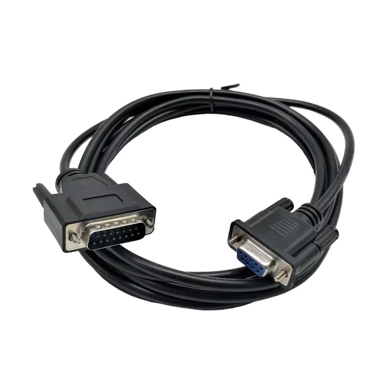
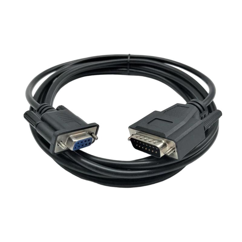
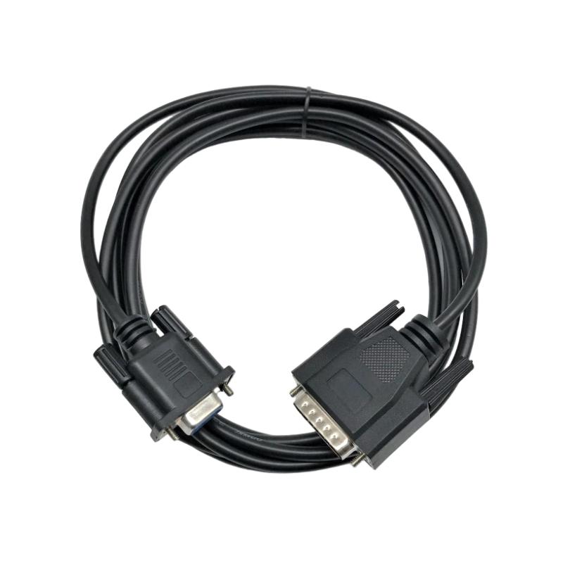
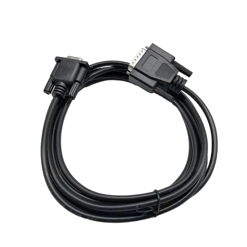
- GE
- IC690ACC901
- Cable
- USA
- Optional
- 3 kg
- Xiamen, China
- New & In Stock
- T/T, PayPal, Western Union
- 1 Year
- 1-3 Working Days
- DHL, UPS, TNT, FedEx and EMS.
- 24-Hour Service
- COO
- 74
Our advantage

Global Logistics
We have a 10-year logistics and express cooperation agreement, so our products can be shipped to any place in the world.

Brand new and original
Our products are imported in bulk from the place of origin. Because of the cooperative relationship, our products are all original and 100% new.

24-hour service
We provide 7*24 hours service to our customers. We will be there whenever you need us.

Price advantage
All our products are priced very favorably because we have our own warehouse and supply.
| Company Information | |||
| [email protected] | |||
| Mobile | +8615980777398 | ||
| +8615980777398 | |||
| 15980777398 |
Product Overview
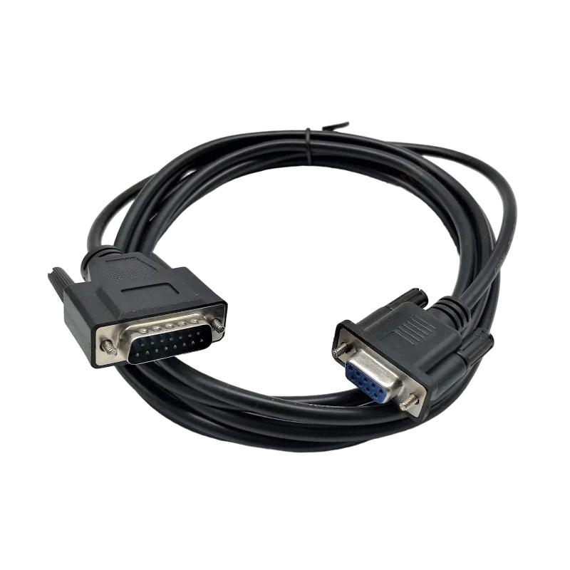
The GE IC690ACC901 Cable is an industrial automation cable used as part of a compatible GE control-system connection architecture. Cables are critical components in PLC and industrial control installations because they provide the physical electrical path required for communication, signal transmission, programming, or interconnection between automation hardware.
The supplied product information identifies the GE IC690ACC901 as a Cable, with an optional cable length and a shipping weight of 3 kg.
Because the cable length is specified as optional, the actual installed length should be verified against the specific part configuration and application requirements before installation.
Product Information
- Manufacturer: GE
- Model: IC690ACC901
- Product Type: Cable
- Cable Length: Optional
- Shipping Weight: 3 kg
- Application: Industrial Automation
- Typical Role: Control-System Interconnection / Signal or Communication Connection
The exact electrical function of a cable should always be confirmed from the complete system configuration before connection. Cable assemblies that appear physically similar may have different wiring, connector assignments, or application purposes.
Technical Specifications
| Parameter | Specification |
|---|---|
| Manufacturer | GE |
| Model Number | IC690ACC901 |
| Product Type | Cable |
| Cable Length | Optional |
| Shipping Weight | 3 kg |
| Application | Industrial Automation |
| System Role | Equipment Interconnection |
| Installation | Industrial Control System |
| Maintenance | Inspection / Replacement / Continuity Testing |
The cable length and shipping weight listed above are based on the product information supplied.
Function and Working Principle
An industrial automation cable provides the physical connection between compatible control-system components.
A simplified connection can be represented as:
Automation Device A
↓
GE IC690ACC901 Cable
↓
Automation Device B
Depending on the intended system architecture, the cable may provide a path for:
- Control signals
- Communication signals
- Programming connections
- Data transmission
- Device-to-device interconnection
The cable itself does not normally perform control logic. Its purpose is to maintain the electrical connection between the associated automation components.
The actual function of the IC690ACC901 depends on the equipment to which it is connected and the specific cable configuration.
Role in Industrial Control Systems
Reliable cable connections are essential for PLC and industrial automation systems.
A typical control architecture may contain:
PLC / Controller
↓
Communication or Interface Hardware
↓
IC690ACC901 Cable
↓
Remote Equipment
↓
I/O / Field Devices
A cable fault can interrupt communication, produce intermittent signals, prevent programming access, or cause connected equipment to appear offline.
For this reason, cable condition should be considered during troubleshooting rather than automatically assuming that an electronic module has failed.
Industrial Applications
PLC Control Systems
The IC690ACC901 can be used as part of compatible GE PLC system interconnections.
Industrial Machine Control
Machine-control systems rely on reliable cables for communication and equipment interconnection.
Manufacturing Automation
Factory automation systems often contain multiple controllers, interfaces, and distributed devices requiring reliable connections.
OEM Equipment
Machine builders can use correctly specified cable assemblies to connect automation components within control cabinets.
Maintenance and Replacement
A compatible cable can be important when restoring an existing automation system after cable damage or connector failure.
Installation Guide
1. Verify the Cable Model
Before installation, confirm:
GE IC690ACC901
Cable
Do not substitute a visually similar cable without verifying its electrical and connector compatibility.
2. Identify the Connected Equipment
Before connecting the cable, identify:
- Source device
- Destination device
- Connector type
- Cable function
- Signal type
- Communication architecture
- Required cable length
The correct cable should be selected based on the complete system configuration.
3. Verify Cable Length
The supplied product information specifies:
Cable Length: Optional
Therefore, verify the actual cable length of the specific IC690ACC901 configuration before installation.
The selected length should allow adequate routing without excessive tension, sharp bends, or unnecessary cable loops.
4. Inspect the Cable
Before installation, inspect:
- Cable jacket
- Connectors
- Pins
- Contacts
- Strain relief
- Shielding
- Labels
- Connector locks
Look for:
- Cuts
- Crushing
- Abrasion
- Corrosion
- Bent pins
- Broken locking mechanisms
- Exposed conductors
Do not install visibly damaged cable assemblies.
5. Power Down When Required
Before connecting or disconnecting the cable:
- Stop the machine or process.
- Place the system in a safe condition.
- Isolate applicable electrical power.
- Follow approved lockout/tagout procedures.
- Verify that the connected equipment is safe to work on.
Do not disconnect energized connections unless the specific system design and applicable procedures explicitly permit it.
6. Route the Cable Correctly
Route the IC690ACC901 away from unnecessary mechanical and electrical stress.
Avoid:
- Sharp bends
- Crushing
- Pinching
- Excessive tension
- Moving mechanical parts
- High-temperature surfaces
- High-current power cables where interference could be a concern
Maintain an appropriate bend radius for the actual cable construction.
7. Connect the Cable
Connect the cable to the designated equipment.
Verify:
- Correct connector
- Correct orientation
- Full connector engagement
- Secure locking mechanism
- No excessive mechanical force
Never force a connector into a socket.
8. Secure the Cable
Provide suitable cable support where required.
The cable should not hang from its connector under excessive mechanical load.
Use appropriate cable management to prevent:
- Vibration damage
- Connector stress
- Accidental disconnection
- Abrasion
- Excessive movement
Commissioning Procedure
Step 1 — Visual Inspection
Inspect the entire cable assembly.
Step 2 — Verify Connections
Confirm that both ends are correctly connected.
Step 3 — Check Connector Security
Make sure connectors are fully engaged and secured.
Step 4 — Verify Cable Routing
Confirm that the cable is not pinched, crushed, or excessively bent.
Step 5 — Energize the System
Restore power according to the approved commissioning procedure.
Step 6 — Check Connected Devices
Verify that the connected equipment starts normally.
Step 7 — Check Communication or Signal Operation
Confirm that the expected communication or signal transfer is functioning.
Step 8 — Test the Application
Perform an appropriate functional test.
Step 9 — Monitor Operation
Observe the system for intermittent communication, signal loss, or unexpected diagnostic conditions.
Troubleshooting Guide
Problem 1: Connected Device Is Not Recognized
Possible causes include:
- Cable disconnected
- Incorrect cable
- Connector not fully engaged
- Damaged cable
- Bent connector pins
- Configuration problem
- Device fault
Diagnostic Procedure
- Verify the IC690ACC901 model.
- Check both connectors.
- Inspect the cable.
- Verify the connected devices.
- Check communication status.
- Test with a known-good compatible cable where appropriate.
Problem 2: Communication Is Intermittent
Possible causes include:
- Loose connector
- Damaged conductor
- Cable movement
- Connector wear
- Electrical interference
- Excessive mechanical stress
- Poor shielding or grounding
Recommended Checks
Inspect the cable while monitoring the affected communication path.
If gently moving the cable causes the fault to appear or disappear, investigate the cable and connector assembly carefully.
Problem 3: Communication Is Completely Lost
Check:
- Cable connection
- Connector condition
- Cable continuity
- Device power
- Communication configuration
- Connected equipment
- Interface hardware
A systematic sequence is:
Power → Device → Connector → Cable → Interface → Configuration
Problem 4: Programming or Service Connection Does Not Work
Possible causes include:
- Incorrect cable
- Incorrect connection point
- Damaged connector
- Cable conductor failure
- Device configuration
- Programming interface problem
Verify the complete connection path before replacing the controller or interface hardware.
Problem 5: Cable Works Intermittently After Machine Movement
Possible causes include:
- Excessive cable bending
- Cable tension
- Connector movement
- Mechanical abrasion
- Internal conductor damage
Inspect the cable routing and mechanical support.
Problem 6: Cable Has Visible Damage
Damage such as:
- Cuts
- Crushing
- Severe abrasion
- Exposed conductors
- Burn marks
- Damaged connectors
may compromise electrical reliability and safety.
Replace the cable with a correctly compatible assembly when damage is significant.
Problem 7: New Cable Does Not Resolve the Fault
If replacing the IC690ACC901 does not correct the problem, investigate:
- Connected devices
- Interface modules
- Power supply
- Controller
- Configuration
- Communication settings
- Other cables in the signal path
The cable may not be the actual source of the fault.
Cable Continuity Testing
Where appropriate and safe, continuity testing can help identify an open conductor.
A basic diagnostic concept is:
Connector A Pin
↓
Cable Conductor
↓
Connector B Pin
A failed continuity test can indicate:
- Broken conductor
- Damaged connector
- Poor contact
- Internal cable damage
However, continuity testing alone does not prove that a cable is suitable for high-speed or noise-sensitive communication. A cable may show continuity while still having shielding, impedance, contact, or intermittent mechanical problems.
Connector Inspection
Connector problems are common sources of intermittent automation faults.
Inspect for:
- Bent pins
- Corroded contacts
- Contamination
- Loose housings
- Damaged locking mechanisms
- Incomplete insertion
- Mechanical wear
If a connector does not seat correctly, do not force it.
Cable Replacement Procedure
Phase 1 — Preparation
- Confirm GE IC690ACC901.
- Verify the replacement cable.
- Confirm the required cable length.
- Identify both connection points.
- Record existing routing.
- Place the system in a safe condition.
Phase 2 — Removal
- Stop the affected equipment.
- Isolate applicable power.
- Verify safe conditions.
- Release connector locks.
- Disconnect both ends.
- Remove the cable without damaging adjacent wiring.
Phase 3 — Installation
- Inspect the replacement cable.
- Verify connector condition.
- Confirm cable length.
- Route the cable correctly.
- Connect both ends.
- Secure the connectors.
- Provide appropriate cable support.
Phase 4 — Verification
- Check connector engagement.
- Inspect cable routing.
- Verify no excessive bending or tension.
- Check continuity where appropriate.
- Restore power.
- Test communication or signal operation.
Preventive Maintenance
| Maintenance Item | Recommended Action |
|---|---|
| Cable Jacket | Inspect for cuts and abrasion |
| Connectors | Check physical condition |
| Pins / Contacts | Inspect for damage |
| Cable Routing | Check for excessive stress |
| Strain Relief | Verify condition |
| Cable Support | Check mounting |
| Connector Locks | Verify engagement |
| Electrical Noise | Inspect routing |
| Labels | Verify identification |
| Communication | Monitor recurring errors |
Environmental Considerations
Temperature
Keep the cable away from excessive heat sources and maintain conditions suitable for the cable construction.
Moisture
Protect connectors and cable assemblies from moisture and condensation.
Dust
Prevent excessive contamination around connectors.
Vibration
Use proper cable support in applications with continuous vibration.
Mechanical Movement
Ensure that moving machinery cannot pull, crush, or repeatedly bend the cable beyond its suitable mechanical limits.
Electrical Noise
Where the cable carries communication or sensitive signals, maintain appropriate separation from high-current and high-noise equipment.
Common Installation Mistakes
Using an Incorrect Cable
A cable that looks similar may have different wiring or connector assignments.
Ignoring Cable Length
The supplied specification identifies the cable length as optional. Verify the actual configuration before installation.
Excessive Cable Tension
Mechanical tension can damage connectors and internal conductors.
Sharp Bends
Excessive bending can damage conductors and shielding.
Poor Cable Routing
Routing close to high-current circuits can increase the risk of electrical interference.
Connecting Under Unsafe Conditions
Follow the applicable equipment isolation and maintenance procedures before disconnecting or connecting the cable.
Replacing Electronic Hardware First
A communication problem may be caused by a cable or connector rather than the PLC or interface module.
Key Advantages
- Provides a physical connection between compatible automation equipment
- Supports organized industrial control-system wiring
- Can simplify equipment interconnection
- Suitable for compatible GE automation architectures
- Useful for PLC and control-system maintenance
- Supports replacement of damaged cable assemblies
- Optional cable-length configuration according to the supplied product information
- Shipping weight of 3 kg
Technical FAQs
What is the GE IC690ACC901?
The GE IC690ACC901 is an industrial automation Cable used as part of a compatible GE control-system interconnection.
What is the cable length of IC690ACC901?
The supplied product information specifies the cable length as optional, so the actual configuration should be verified before installation.
What is the shipping weight of IC690ACC901?
The supplied shipping weight is 3 kg.
What can cause an IC690ACC901 communication fault?
Possible causes include loose connectors, damaged conductors, incorrect cable selection, connector damage, electrical interference, or problems with connected equipment.
How can I troubleshoot an intermittent cable fault?
Inspect both connectors, cable routing, strain relief, mechanical movement, and the cable jacket. Continuity and substitution testing can also help identify faults where appropriate.
Can a cable have continuity but still be faulty?
Yes. Continuity testing may not detect intermittent contact problems, shielding problems, connector faults, or other signal-integrity issues.
Why should I verify the exact cable model?
Industrial automation cables may have different internal wiring and connector assignments even when they look physically similar.
Can cable routing affect communication?
Yes. Poor routing, excessive bending, mechanical stress, and proximity to high-current equipment can contribute to communication problems.
Should I replace the controller if communication is lost?
Not immediately. Check power, connectors, cable condition, communication hardware, and configuration before replacing the controller.
What should be checked before installing IC690ACC901?
Verify the model, cable configuration, required length, connector compatibility, connected devices, and installation routing.
How should IC690ACC901 be replaced?
Place the system in a safe state, isolate applicable power, disconnect the existing cable, inspect the replacement, route it correctly, secure both connectors, and perform a functional test.
What is the most effective way to diagnose a cable-related fault?
Trace the complete connection path from one connected device to the other and verify the cable, connectors, power, interfaces, and communication configuration systematically.
Conclusion
The GE IC690ACC901 Cable is an industrial automation cable intended for use within a compatible GE control-system architecture. Based on the supplied product information, its cable length is optional and its shipping weight is 3 kg.
Reliable operation depends on correct cable selection, compatible connectors, proper installation, suitable routing, secure connections, and protection from excessive mechanical and environmental stress.
When a communication or signal problem occurs, technicians should inspect the cable and connectors as part of the initial diagnostic process. Checking the complete connection path can prevent unnecessary replacement of PLCs, interface modules, and other expensive automation hardware.
Proper cable management, periodic connector inspection, continuity testing where appropriate, and systematic troubleshooting can improve long-term reliability in industrial automation installations.