

ProductPRODUCT
Featured products



Contact Us
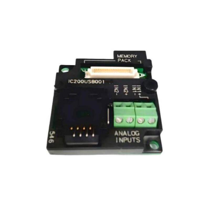
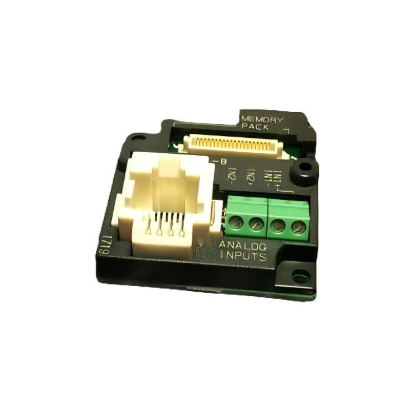
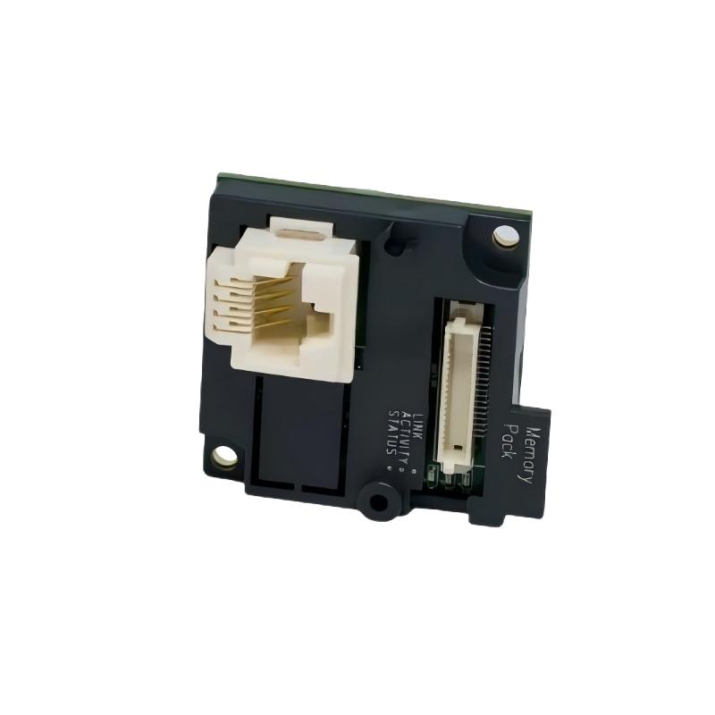
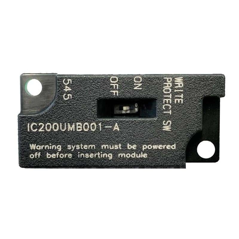
- GE
- IC200USB001
- RS-232 Communication Option Board
- USA
- 56 x 70 x 20 mm
- 0.06 kg
- Xiamen, China
- New & In Stock
- T/T, PayPal, Western Union
- 1 Year
- 1-3 Working Days
- DHL, UPS, TNT, FedEx and EMS.
- 24-Hour Service
- COO
- 77
Our advantage

Global Logistics
We have a 10-year logistics and express cooperation agreement, so our products can be shipped to any place in the world.

Brand new and original
Our products are imported in bulk from the place of origin. Because of the cooperative relationship, our products are all original and 100% new.

24-hour service
We provide 7*24 hours service to our customers. We will be there whenever you need us.

Price advantage
All our products are priced very favorably because we have our own warehouse and supply.
| Company Information | |||
| [email protected] | |||
| Mobile | +8615980777398 | ||
| +8615980777398 | |||
| 15980777398 |
Product Overview
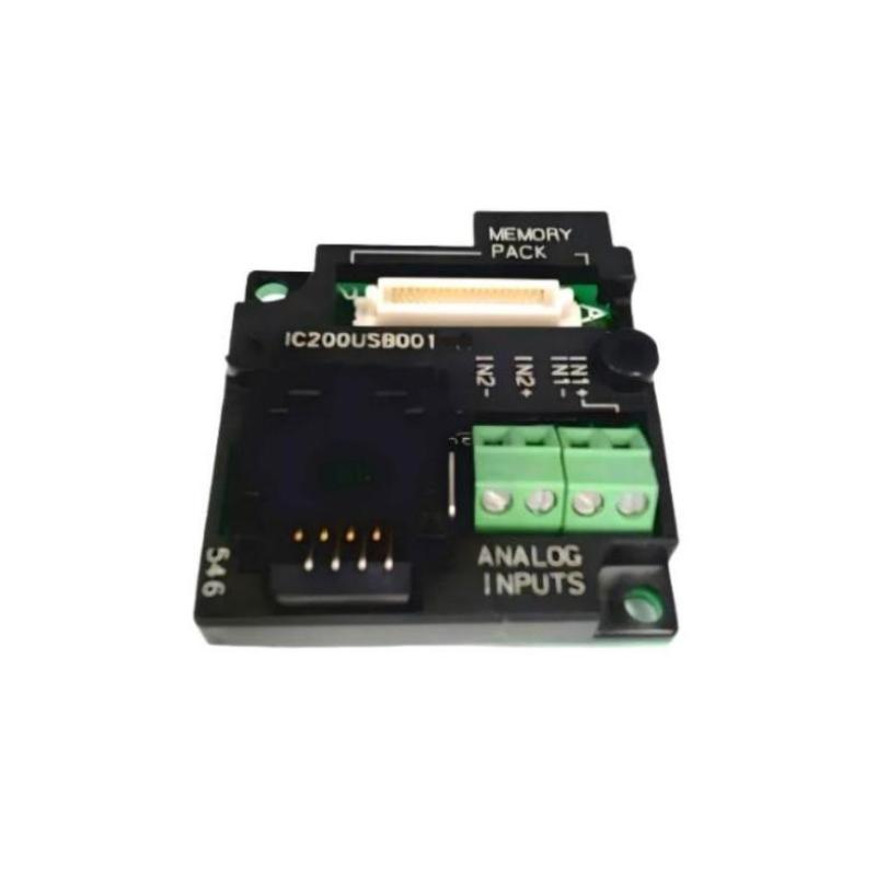
The GE IC200USB001 RS-232 Communication Option Board is a compact communication interface component designed for use with compatible GE VersaMax industrial automation equipment. Its primary purpose is to provide an RS-232 serial communication interface within an automation system, allowing compatible devices to exchange data through a serial communication connection.
Serial communication remains useful in industrial automation for connecting controllers, programming equipment, operator interfaces, configuration tools, and other compatible devices. When installed correctly, an RS-232 communication option can provide a straightforward point-to-point communication path for system configuration, diagnostics, or data exchange.
The supplied product information identifies the GE IC200USB001 as an RS-232 Communication Option Board, with dimensions of 56 × 70 × 20 mm and a weight of 0.06 kg.
Product Information
- Manufacturer: GE
- Product Family: VersaMax
- Model: IC200USB001
- Product Type: RS-232 Communication Option Board
- Communication Interface: RS-232
- Dimensions: 56 × 70 × 20 mm
- Weight: 0.06 kg
- Application: Industrial Automation
- System Role: Serial Communication Interface
The IC200USB001 should be installed only in equipment and configurations that support this communication option. Before installation, verify the host device, electrical interface requirements, communication settings, and physical installation arrangement.
Technical Specifications
| Parameter | Specification |
|---|---|
| Manufacturer | GE |
| Product Family | VersaMax |
| Model Number | IC200USB001 |
| Product Type | RS-232 Communication Option Board |
| Communication Interface | RS-232 |
| Dimensions | 56 × 70 × 20 mm |
| Weight | 0.06 kg |
| Application | Industrial Automation |
| Communication Type | Serial Communication |
| Installation | Compatible Automation Equipment |
| Maintenance | Installation / Configuration / Troubleshooting |
The dimensions and weight above are based on the product information supplied.
Function and Working Principle
The IC200USB001 provides an RS-232 serial communication interface for a compatible automation system.
A simplified communication structure can be represented as:
Industrial Controller / Host Equipment
↓
IC200USB001 RS-232 Interface
↓
RS-232 Serial Connection
↓
Compatible External Device
The board acts as the electrical communication interface between the host equipment and a compatible RS-232 device.
Depending on the host system and application, serial communication may be used for:
- Configuration
- Programming
- Diagnostics
- Data exchange
- Operator interface communication
- Equipment integration
- Maintenance access
RS-232 is generally intended for point-to-point serial communication rather than a large multidrop network. Therefore, technicians should verify the intended connection architecture before selecting the interface for a particular application.
Role in Industrial Control Systems
Communication interfaces are an important part of modern automation systems because controllers frequently need to exchange information with external devices.
A representative architecture is:
Automation Controller
↓
IC200USB001
↓
RS-232 Serial Link
↓
External Device
The external device may be a compatible:
- Programming computer
- Operator interface
- Configuration device
- Serial instrument
- Industrial controller
- Data collection device
The actual application depends on the capabilities of the host equipment and the communication protocol being used.
RS-232 Communication Characteristics
RS-232 is commonly used for point-to-point serial communication.
Typical communication parameters can include:
- Baud rate
- Data bits
- Stop bits
- Parity
- Flow control
- Transmission mode
- Device addressing where supported by the application protocol
The exact settings must match the communicating devices.
For example, if one device is configured for one serial communication format while the other device uses a different format, the physical connection may be correct but communication will still fail.
Therefore:
Correct Wiring + Correct Communication Parameters + Compatible Protocol = Reliable Communication
Industrial Applications
PLC Programming and Maintenance
The IC200USB001 can provide an RS-232 interface for compatible programming or maintenance applications.
Operator Interface Communication
Where supported by the host system, an RS-232 connection can be used to exchange data with an operator interface.
Serial Instrument Integration
Industrial instruments equipped with compatible serial interfaces can be connected through an appropriate RS-232 communication arrangement.
Equipment Configuration
Technicians can use serial communication for configuration and diagnostic activities where supported.
Legacy Automation Equipment
RS-232 remains useful when integrating newer control equipment with legacy serial devices.
OEM Machinery
Machine builders can use serial communication interfaces when an automation system requires a compact point-to-point communication connection.
Installation Guide
1. Confirm the Product Model
Before installation, verify:
GE IC200USB001
RS-232 Communication Option Board
Do not substitute a different communication option based only on physical appearance.
2. Verify Host Equipment Compatibility
Before installing the board, identify the host automation equipment.
Confirm:
- Host device model
- Supported communication options
- Option-board mounting arrangement
- Required communication interface
- Application requirements
- Controller configuration
The option board should only be installed in a compatible host environment.
3. Back Up Existing Configuration
Before modifying automation hardware, preserve the existing system configuration.
Record or back up:
- Controller program
- Hardware configuration
- Communication settings
- Application parameters
- Existing serial settings
- Device configuration
This provides a recovery point if the communication system does not operate after installation.
4. Place the Equipment in a Safe State
Before installation:
- Stop automatic operation.
- Place the machine in a safe state.
- Identify affected equipment.
- Isolate power where required.
- Follow applicable lockout/tagout procedures.
- Verify that the equipment cannot unexpectedly move or start.
5. Inspect the IC200USB001
Before installation, visually inspect the board.
Check for:
- Damaged PCB
- Cracked components
- Bent connector pins
- Corrosion
- Contamination
- Scratches or impact damage
- Loose components
Do not install a visibly damaged communication board.
6. Check Installation Space
The supplied dimensions are:
56 × 70 × 20 mm
Although the board is compact, additional space may be required for:
- Mounting
- Cabling
- Connector access
- Cable bend radius
- Ventilation
- Maintenance
Do not design the installation around the board dimensions alone.
7. Install the Communication Board
Install the IC200USB001 into the appropriate host equipment according to the mechanical arrangement of the host system.
Check:
- Correct orientation
- Proper alignment
- Secure mounting
- Connector engagement
- Mechanical clearance
Do not force the board into position.
8. Connect the RS-232 Interface
Before connecting the serial cable, confirm the intended RS-232 connection.
Verify:
- Connector compatibility
- Signal assignment
- Cable type
- Cable length
- Shielding arrangement where applicable
- Grounding arrangement
- External device interface
RS-232 connections should not be wired solely according to connector shape. Signal assignments must be verified before applying the connection.
9. Verify Communication Parameters
Confirm the settings on both communicating devices.
Typical parameters include:
- Baud rate
- Data bits
- Parity
- Stop bits
- Flow control
Both devices must use compatible settings.
Commissioning Procedure
Step 1 — Visual Inspection
Inspect the IC200USB001 and the host equipment.
Step 2 — Verify Installation
Confirm that the communication board is correctly installed.
Step 3 — Verify Cable Connections
Check the RS-232 cable and connector engagement.
Step 4 — Verify Communication Parameters
Confirm that both devices use compatible serial settings.
Step 5 — Power the System
Restore power according to the approved commissioning procedure.
Step 6 — Check System Status
Verify normal host-system startup.
Step 7 — Test Serial Communication
Establish communication with the connected device.
Step 8 — Check Data Exchange
Verify that transmitted and received data are correct.
Step 9 — Test Under Operating Conditions
Run the communication link under normal application conditions.
Step 10 — Document the Configuration
Record the final communication settings and connected-device information.
Troubleshooting Guide
Problem 1: No RS-232 Communication
Possible causes include:
- Incorrect cable
- Incorrect signal wiring
- Loose connector
- Incorrect baud rate
- Incorrect parity
- Incorrect stop bits
- Incorrect data format
- Incompatible protocol
- Host configuration problem
- External device problem
Recommended Checks
- Verify the IC200USB001 installation.
- Check the serial cable.
- Confirm signal assignments.
- Check connector engagement.
- Compare communication parameters.
- Verify the protocol used by both devices.
- Check diagnostics on the host equipment.
Problem 2: Communication Is Intermittent
Possible causes include:
- Loose connector
- Damaged cable
- Electrical interference
- Poor grounding
- Excessive cable length
- Mechanical vibration
- Unstable external equipment
Recommended Checks
Inspect the physical communication path before changing software settings.
Pay particular attention to:
- Connector condition
- Cable routing
- Cable shielding
- Grounding
- Nearby high-power equipment
- Cable movement
Problem 3: Data Is Garbled
Garbled or unreadable serial data often indicates a communication-parameter mismatch.
Check:
- Baud rate
- Data bits
- Parity
- Stop bits
- Flow control
- Protocol configuration
For example, if the transmitting and receiving devices use different baud rates, the physical link may appear active while the received data is unusable.
Problem 4: Device Does Not Respond
Possible causes include:
- Incorrect protocol
- Incorrect serial parameters
- Incorrect signal wiring
- External-device fault
- Communication software configuration
- Incorrect device mode
Check both the physical connection and application-level communication settings.
Problem 5: Communication Works During Testing but Fails During Operation
Possible causes include:
- Electrical noise
- Increased system activity
- Timing problems
- Application configuration
- Cable interference
- External device loading
Compare communication behavior during idle conditions and normal machine operation.
If the problem appears only when motors, drives, contactors, or other high-current equipment operate, investigate electrical interference and cable routing.
Problem 6: Communication Stops After System Restart
Check:
- Startup configuration
- Host configuration
- Communication parameters
- External device startup sequence
- Cable connection
- Application initialization
A communication system that works manually but fails after restart may have an initialization or configuration problem.
Problem 7: IC200USB001 Is Not Detected by the Host
Possible causes include:
- Incorrect installation
- Poor board connection
- Host incompatibility
- Configuration problem
- Hardware fault
Diagnostic Procedure
- Power down the system safely.
- Verify board installation.
- Inspect connectors.
- Confirm host compatibility.
- Restore power.
- Review host diagnostics.
- Compare the configuration with the intended hardware arrangement.
Problem 8: Communication Fails After Replacing the Board
If communication fails after replacing an IC200USB001, verify:
- Replacement model
- Board installation
- Cable connection
- Communication parameters
- Host configuration
- External-device configuration
Do not immediately conclude that the replacement board is defective.
RS-232 Troubleshooting Method
A practical troubleshooting sequence is:
Power
↓
Host Equipment
↓
IC200USB001 Installation
↓
Connector
↓
RS-232 Cable
↓
Signal Wiring
↓
Serial Parameters
↓
Communication Protocol
↓
External Device
This method helps isolate whether the problem is electrical, mechanical, configuration-related, or application-related.
Communication Cable Inspection
When troubleshooting an RS-232 connection, inspect the entire cable rather than only the connectors.
Check for:
- Broken conductors
- Damaged insulation
- Bent pins
- Loose terminals
- Incorrect wiring
- Poor shielding
- Excessive cable stress
- Excessive cable length
A cable that appears physically intact can still have an open conductor or incorrect signal assignment.
Installation and Wiring Considerations
Signal Integrity
Keep serial communication wiring away from sources of significant electrical interference.
Potential sources include:
- Variable-frequency drives
- Motors
- Contactors
- High-current power cables
- Switching power equipment
Cable Routing
Avoid running RS-232 communication cables parallel to high-power cables for long distances.
Where control-cabinet design permits, separate communication wiring from power wiring.
Grounding
Use the grounding arrangement appropriate for the complete system. Improper grounding can contribute to communication instability or electrical interference.
Module Replacement Procedure
Phase 1 — Preparation
- Confirm GE IC200USB001.
- Verify the replacement board.
- Back up system configuration.
- Record communication settings.
- Record connected-device information.
- Place the equipment in a safe state.
Phase 2 — Removal
- Stop the system.
- Isolate power as required.
- Verify safe conditions.
- Disconnect the RS-232 cable.
- Remove the existing communication board carefully.
Phase 3 — Installation
- Inspect the replacement IC200USB001.
- Confirm the model number.
- Align the board correctly.
- Install it securely.
- Reconnect the RS-232 interface.
- Inspect cable routing.
Phase 4 — Configuration
- Verify the host configuration.
- Confirm serial communication settings.
- Verify the communication protocol.
- Confirm external-device parameters.
Phase 5 — Testing
- Restore power.
- Check host startup.
- Verify board recognition.
- Test communication.
- Verify transmitted data.
- Verify received data.
- Test the system under normal operating conditions.
Preventive Maintenance
| Maintenance Item | Recommended Action |
|---|---|
| IC200USB001 | Inspect physical condition |
| Board Mounting | Verify secure installation |
| Connectors | Check engagement |
| RS-232 Cable | Inspect condition |
| Signal Wiring | Verify integrity |
| Communication Settings | Maintain documentation |
| Cable Routing | Keep away from major interference sources |
| Grounding | Verify system arrangement |
| Host Equipment | Review diagnostics |
| External Device | Check communication status |
| Configuration | Maintain verified backup |
Common Installation Mistakes
Using the Wrong Communication Board
Always verify the complete IC200USB001 model number.
Incorrect Serial Wiring
An RS-232 connector may physically fit while the signal assignment is incorrect. Verify the required signal connections before commissioning.
Mismatched Communication Parameters
The communicating devices must use compatible serial parameters.
Poor Cable Routing
Routing RS-232 cables alongside high-current power wiring can increase susceptibility to electrical interference.
Loose Connectors
A loose serial connector can create intermittent communication failures.
Changing Multiple Parameters at Once
During troubleshooting, change one variable at a time whenever possible. This makes it easier to identify the actual cause of the fault.
Key Advantages
- Compact RS-232 communication interface
- Designed for compatible GE VersaMax automation equipment
- Supports serial communication applications
- Suitable for point-to-point communication
- Compact dimensions of 56 × 70 × 20 mm
- Low weight of 0.06 kg
- Useful for configuration and maintenance applications
- Can support communication with compatible external serial equipment
- Provides a dedicated communication option within a modular automation architecture
Technical FAQs
What is the GE IC200USB001?
The GE IC200USB001 is an RS-232 Communication Option Board intended for compatible GE VersaMax automation equipment.
What communication interface does IC200USB001 provide?
The IC200USB001 provides an RS-232 serial communication interface.
What are the dimensions of IC200USB001?
The supplied dimensions are 56 × 70 × 20 mm.
What is the weight of IC200USB001?
The supplied weight is 0.06 kg.
What can RS-232 be used for in industrial automation?
RS-232 can be used for compatible applications such as configuration, diagnostics, programming, operator-interface communication, and point-to-point data exchange.
Why is RS-232 communication not working?
Check the board installation, cable, signal wiring, connector condition, baud rate, data bits, parity, stop bits, flow control, and communication protocol.
Why is the received serial data corrupted?
A mismatch in serial communication parameters is a common cause. Verify the communication settings on both devices.
Can electrical noise affect RS-232 communication?
Yes. Nearby motors, drives, contactors, and high-current switching equipment can contribute to communication interference.
Why does communication work intermittently?
Inspect connectors, cable condition, cable routing, grounding, electrical interference, and mechanical vibration.
Should the IC200USB001 be replaced immediately when communication fails?
No. Verify the cable, signal wiring, serial parameters, host configuration, external device, and communication protocol before replacing the board.
What should be recorded before replacing an IC200USB001?
Record the host configuration, serial parameters, connected device, communication protocol, cable arrangement, and existing system behavior.
How can an IC200USB001 communication fault be isolated?
Follow the path from power and host equipment through the option board, connector, cable, signal wiring, serial parameters, protocol, and external device.
Conclusion
The GE IC200USB001 RS-232 Communication Option Board is a compact communication component for compatible GE VersaMax industrial automation applications. The supplied product information specifies dimensions of 56 × 70 × 20 mm and a weight of 0.06 kg.
Reliable operation depends on correct host compatibility, proper board installation, appropriate RS-232 wiring, secure connectors, compatible communication parameters, and correct application-level protocol configuration.
When commissioning the IC200USB001, technicians should verify the physical installation first, followed by the RS-232 cable, signal wiring, serial parameters, communication protocol, and external device.
For troubleshooting, a systematic approach is preferable to immediate hardware replacement. Checking the host equipment, board installation, cable, signal path, communication parameters, and external device can help identify the actual source of communication problems and reduce unnecessary downtime.