

ProductPRODUCT
Featured products



Contact Us

- GE
- IC200UDR140
- VersaMax Microcontroller Processor
- USA
- 120 × 65 × 130 mm
- 0.39 kg
- Xiamen, China
- New & In Stock
- T/T, PayPal, Western Union
- 1 Year
- 1-3 Working Days
- DHL, UPS, TNT, FedEx and EMS.
- 24-Hour Service
- COO
- 46
Our advantage

Global Logistics
We have a 10-year logistics and express cooperation agreement, so our products can be shipped to any place in the world.

Brand new and original
Our products are imported in bulk from the place of origin. Because of the cooperative relationship, our products are all original and 100% new.

24-hour service
We provide 7*24 hours service to our customers. We will be there whenever you need us.

Price advantage
All our products are priced very favorably because we have our own warehouse and supply.
| Company Information | |||
| [email protected] | |||
| Mobile | +8615980777398 | ||
| +8615980777398 | |||
| 15980777398 |
Product Overview
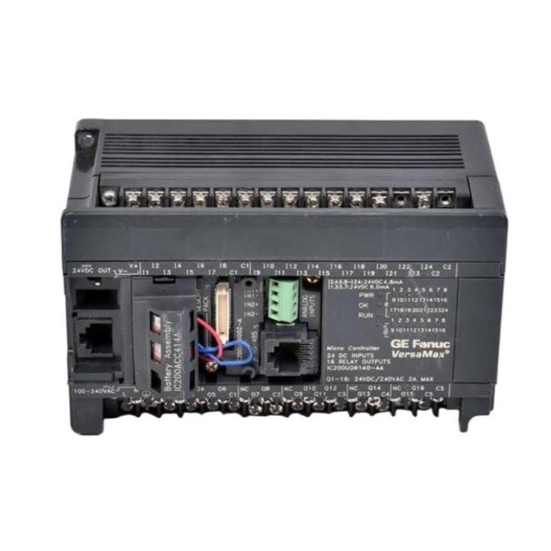
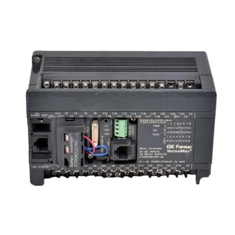
The GE IC200UDR140 VersaMax Microcontroller Processor is a compact programmable controller designed for industrial automation applications. It belongs to the VersaMax Micro PLC family and functions as a central control element for processing field inputs, executing application logic, and controlling connected output devices.
The IC200UDR140 is a 40-point Micro PLC configuration with 24 DC inputs and 16 normally open relay outputs. The controller is designed for 120/240 VAC operating power, distinguishing it from related VersaMax Micro controllers that use DC power supplies. The relay outputs can be used to control suitable field loads such as motor starters, solenoids, and indicators.
The supplied product information specifies dimensions of 120 × 65 × 130 mm and a weight of 0.39 kg.
Product Information
- Manufacturer: GE
- Product Family: VersaMax
- Model: IC200UDR140
- Product Type: VersaMax Microcontroller Processor / Micro PLC
- Configuration: 40-point Micro PLC
- Inputs: 24 × DC inputs
- Outputs: 16 × relay outputs
- Power Supply: 120/240 VAC
- Dimensions: 120 × 65 × 130 mm
- Weight: 0.39 kg
- Application: Industrial Automation
- System Role: Programmable Controller
Technical Specifications
| Parameter | Specification |
|---|---|
| Manufacturer | GE |
| Product Family | VersaMax |
| Model Number | IC200UDR140 |
| Product Type | Microcontroller Processor / Micro PLC |
| Controller Type | VersaMax Micro 40 |
| Digital Inputs | 24 × DC inputs |
| Relay Outputs | 16 × normally open relay outputs |
| Relay Output Rating | 2 A per output circuit |
| PLC Operating Power | 120/240 VAC |
| Supplied Dimensions | 120 × 65 × 130 mm |
| Supplied Weight | 0.39 kg |
| Application | Industrial Automation |
| Control Function | Programmable Logic Control |
The model-specific electrical information above is based on available VersaMax technical documentation, while the dimensions and weight follow the product information supplied for this article.
Function and Working Principle
The IC200UDR140 combines controller processing, DC input circuits, relay output circuits, and the controller power system in a compact Micro PLC platform.
A simplified operating structure is:
Field Sensors
↓
24 DC Inputs
↓
IC200UDR140 Processor
↓
User Application Logic
↓
16 Relay Outputs
↓
Motors / Solenoids / Contactors / Indicators
During operation, the controller monitors its input circuits, processes the received information according to the application program, and updates the output states.
The controller can therefore perform functions such as:
- Machine sequencing
- Start/stop logic
- Interlocking
- Timer operations
- Counter operations
- Alarm logic
- Equipment coordination
- Digital signal processing
- High-speed input functions where configured
- Relay-based output control
The VersaMax Micro 40 architecture also supports expansion capabilities, allowing the controller to be incorporated into larger automation configurations.
24-Input and 16-Relay-Output Architecture
One of the defining characteristics of the IC200UDR140 is its combination of 24 DC inputs and 16 relay outputs.
The 24 inputs can be used with devices such as:
- Pushbuttons
- Limit switches
- Proximity switches
- Digital sensors
- Machine-position switches
- Other compatible DC field devices
The 16 relay outputs provide normally open Form A switching circuits. These outputs can be used for suitable control loads including:
- Motor starters
- Solenoids
- Indicators
- Contactors
- Interposing relays
The relay outputs have a stated switching capacity of 2 A per circuit, and an external source of AC or DC power is used to operate field loads.
Role in Industrial Control Systems
The IC200UDR140 is positioned between field-level devices and higher-level automation functions.
A typical system can be represented as:
Sensors
↓
IC200UDR140 Inputs
↓
PLC Processing
↓
IC200UDR140 Relay Outputs
↓
Actuators
The controller can also exchange information with an operator interface or other automation equipment.
HMI
↕
Communication Interface
↕
IC200UDR140
↕
Field I/O
↕
Machine Equipment
This arrangement makes the controller suitable for compact machines and standalone control applications where a combination of digital inputs and relay outputs is required.
Installation Guide
1. Verify the Model
Before installation, confirm that the controller is:
GE IC200UDR140
Do not confuse the IC200UDR140 with similar VersaMax Micro models such as the IC200UDR040 or IC200UDR440. These models have similar I/O configurations but different controller power arrangements. The IC200UDR040 uses a 24 VDC controller supply, while the IC200UDR140 uses 120/240 VAC and the IC200UDR440 uses 12/24 VDC.
2. Verify the Electrical Requirements
The IC200UDR140 is intended for a 120/240 VAC controller power supply.
Before connecting power, verify:
- Incoming voltage
- Frequency
- Power wiring
- Protective grounding
- Terminal connections
- Circuit protection
- Power isolation
- Cabinet wiring
Do not connect a DC supply to the controller power input simply because other VersaMax Micro models use DC power.
3. Inspect the Controller
Before installation, inspect the unit for:
- Cracked housing
- Damaged terminals
- Bent connectors
- Contamination
- Signs of impact
- Corrosion
- Loose components
Do not install visibly damaged equipment.
4. Prepare the Control Cabinet
The cabinet should provide:
- Adequate ventilation
- Mechanical protection
- Appropriate grounding
- Separation from excessive electrical noise
- Protection from moisture and contamination
- Sufficient wiring space
Keep high-energy switching equipment and noisy power conductors appropriately separated from sensitive control wiring.
5. Mount the Controller
Install the IC200UDR140 securely in its intended control-system location.
Verify:
- Correct orientation
- Secure mechanical mounting
- Adequate clearance
- Proper terminal access
- No mechanical stress on the enclosure
- Correct routing of field wiring
Do not apply excessive mechanical force during installation.
6. Connect the 24 DC Inputs
The controller provides 24 DC input circuits.
Before connecting field devices, identify:
- Input channels
- Common terminals
- Sensor supply arrangement
- Positive/negative logic requirements
- Field-device voltage
- Input wiring polarity
Suitable field devices can include switches, pushbuttons, limit switches, and proximity sensors.
7. Connect the Relay Outputs
The IC200UDR140 provides 16 normally open relay outputs.
Typical controlled loads include:
- Motor starters
- Solenoid valves
- Contactors
- Pilot devices
- Indicators
- Interposing relays
Because relay outputs can switch external AC or DC loads, verify the actual load characteristics before commissioning.
Do not exceed the applicable output rating.
8. Check Output Common Groups
Before applying power, inspect the relay output wiring carefully.
Verify:
- Output channel assignment
- Common terminal assignment
- Load voltage
- Load current
- External supply
- Protective devices
- Wiring polarity where applicable
The relay output circuits are arranged into common groups, so incorrect common wiring can affect several outputs simultaneously.
9. Verify Communication and Expansion Connections
Where applicable, inspect:
- Serial communication connections
- Expansion interfaces
- Optional communication equipment
- External memory components
- HMI connections
- Network wiring
The VersaMax Micro platform supports expansion and optional communication capabilities depending on the configuration.
Commissioning Procedure
Step 1 — Visual Inspection
Inspect the IC200UDR140 and all connected equipment.
Step 2 — Verify Power
Confirm that the controller power source matches the required AC supply arrangement.
Step 3 — Verify Input Wiring
Check all 24 input circuits.
Step 4 — Verify Output Wiring
Check all 16 relay output circuits and their external load supplies.
Step 5 — Check the Application
Confirm that the correct control program and configuration are loaded.
Step 6 — Check Controller Status
Verify that the controller reaches the expected operating state.
Step 7 — Test Inputs
Operate field switches and sensors individually and confirm that the corresponding input states change correctly.
Step 8 — Test Outputs
Test outputs individually under controlled conditions.
Step 9 — Test Sequences
Run the machine through controlled operating sequences.
Step 10 — Return to Automatic Operation
After all checks are completed, return the machine or process to normal operation.
Troubleshooting Guide
Problem 1: IC200UDR140 Does Not Power Up
Possible causes include:
- Incorrect AC voltage
- Missing incoming power
- Incorrect wiring
- Open circuit protection
- Loose terminal
- Internal controller fault
Recommended Checks
- Verify incoming voltage.
- Verify power frequency.
- Inspect power terminals.
- Check protective devices.
- Inspect wiring.
- Check controller status indicators.
- Verify that the correct model is installed.
The IC200UDR140 uses 100–240 VAC nominal controller input power, with the documented operating range extending around that nominal supply.
Problem 2: Controller Powers Up but Does Not Control the Machine
Possible causes include:
- Controller not in the expected operating state
- Incorrect application program
- I/O configuration problem
- Input wiring fault
- Output interlock
- Application logic problem
Check controller status before replacing hardware.
Problem 3: Inputs Do Not Change State
Possible causes include:
- Failed sensor
- Incorrect sensor wiring
- Missing sensor supply
- Incorrect input common
- Damaged input circuit
- Broken field cable
- Application configuration problem
Diagnostic Method
First test the field device.
Then verify the voltage at the controller input terminal.
Finally, compare the physical input state with the software input state.
Problem 4: One Input Is Permanently ON
Possible causes include:
- Shorted field wiring
- Incorrect sensor connection
- Incorrect common connection
- Faulty input device
- Input circuit problem
Disconnecting the field device under an approved maintenance procedure can help determine whether the condition originates in the field circuit or controller input.
Problem 5: One Input Is Permanently OFF
Check:
- Sensor operation
- Field voltage
- Wiring continuity
- Input common
- Terminal connections
- Input channel condition
If the field voltage is correct but the controller does not recognize the signal, investigate the input circuit and configuration.
Problem 6: Relay Output Does Not Operate
Possible causes include:
- Incorrect application logic
- Output interlock
- Faulty relay circuit
- Missing external load power
- Incorrect common wiring
- Open field wiring
- Failed load device
Check the commanded output state first, then inspect the physical relay circuit.
Problem 7: Several Relay Outputs Do Not Operate
When multiple outputs in the same group fail simultaneously, investigate the shared circuit first.
Check:
- Output common
- External load supply
- Protective device
- Wiring
- Common terminal
- Group configuration
A common power or wiring fault can affect multiple relay outputs without indicating a processor failure.
Problem 8: Relay Output Operates but Load Does Not Run
Possible causes include:
- Open load circuit
- Failed motor starter
- Failed contactor
- Incorrect external supply
- Blown protective device
- Broken field wiring
- Incorrect load connection
Verify the voltage downstream of the relay output under controlled conditions.
Problem 9: Controller Repeatedly Resets
Potential causes include:
- Unstable AC power
- Electrical interference
- Loose power terminals
- Incorrect supply voltage
- Environmental conditions
- Internal controller fault
Check incoming power while monitoring controller behavior.
Problem 10: Communication Is Lost
Possible causes include:
- Loose communication cable
- Incorrect configuration
- Faulty interface
- Network problem
- External equipment fault
- Controller configuration issue
Troubleshoot the physical communication path before changing application parameters.
Problem 11: Machine Sequence Stops Unexpectedly
Check:
- Input states
- Program conditions
- Timers
- Counters
- Interlocks
- Output states
- Communication signals
- Field-device operation
A sequence fault is not necessarily caused by the processor hardware.
Problem 12: Controller Replacement Does Not Solve the Problem
If replacing the IC200UDR140 does not correct the fault, inspect:
- AC power system
- Input devices
- Output loads
- Field wiring
- Communication equipment
- Application program
- Configuration
- External expansion equipment
This prevents unnecessary replacement of functioning hardware.
Diagnostic Strategy
A structured diagnostic path is:
AC Power
↓
IC200UDR140 Controller
↓
Input Signals
↓
Application Logic
↓
Relay Outputs
↓
Field Loads
For an input problem:
Sensor
→ Field Wiring
→ Input Terminal
→ Controller Input State
For an output problem:
Application Command
→ Relay Output
→ External Supply
→ Load
This approach helps isolate the actual source of a control-system fault.
Processor Replacement Procedure
Phase 1 — Preparation
- Confirm the exact model IC200UDR140.
- Record the existing controller configuration.
- Back up the application.
- Document I/O assignments.
- Document communication settings.
- Identify connected equipment.
- Place the controlled machine in a safe state.
Phase 2 — Removal
- Follow the approved shutdown procedure.
- Isolate power.
- Verify the absence of hazardous energy as required.
- Identify field connections.
- Disconnect wiring carefully.
- Remove the existing controller.
Phase 3 — Installation
- Inspect the replacement IC200UDR140.
- Verify the model.
- Install the controller securely.
- Reconnect input wiring.
- Reconnect relay output wiring.
- Verify common terminals.
- Verify AC power connections.
- Inspect all wiring before energization.
Phase 4 — Configuration
- Restore the correct application.
- Verify I/O assignments.
- Verify controller configuration.
- Verify communication settings.
- Review available diagnostics.
Phase 5 — Commissioning
- Apply control power.
- Confirm controller startup.
- Check status indications.
- Test inputs.
- Test outputs.
- Verify communication.
- Test machine sequences.
- Return the system to service.
Preventive Maintenance
| Maintenance Item | Recommended Action |
|---|---|
| IC200UDR140 | Inspect controller condition |
| AC Power | Verify stable supply |
| Input Terminals | Inspect connections |
| Relay Outputs | Inspect terminals and load circuits |
| Field Wiring | Check for looseness or damage |
| Communication | Inspect cables and connectors |
| Application | Maintain verified backup |
| Hardware Configuration | Document changes |
| Cabinet | Keep clean and dry |
| Grounding | Inspect system arrangement |
| Diagnostics | Review recurring faults |
| Maintenance Records | Document service activities |
Environmental Considerations
Temperature
Excessive cabinet temperature can reduce electronic component reliability and increase the probability of intermittent operation.
Dust
Dust can accumulate around terminals and ventilation areas and should be controlled through appropriate cabinet maintenance.
Moisture
Moisture and condensation can produce corrosion and electrical leakage.
Vibration
Continuous vibration can loosen wiring and mechanical connections.
Electrical Noise
The controller may be installed near contactors, motors, drives, and other switching equipment. Appropriate wiring separation, grounding, and cabinet practices can reduce electrical interference.
Common Installation Mistakes
Confusing IC200UDR140 with IC200UDR040
These models have similar 24-input/16-relay-output configurations, but their controller power requirements differ. The IC200UDR140 uses 120/240 VAC, while the IC200UDR040 uses 24 VDC.
Applying the Wrong Power Supply
Never assume that a VersaMax Micro controller can accept the same supply as another model.
Ignoring Relay Output Load Requirements
Relay outputs must be used within their applicable switching limitations.
Incorrect Common Wiring
A common wiring error can disable multiple relay outputs simultaneously.
Failing to Back Up the Application
Always preserve the existing application and configuration before controller replacement.
Testing Outputs Without Considering Connected Loads
Output testing should be performed under controlled conditions because relay outputs can directly control industrial equipment.
Key Advantages
- VersaMax Micro PLC architecture
- Compact programmable controller design
- 24 DC input circuits
- 16 relay output circuits
- 2 A relay output switching capacity per circuit
- 120/240 VAC controller power configuration
- Suitable for machine automation
- Suitable for process-control applications
- Suitable for OEM equipment
- Supports modular expansion
- Suitable for digital control applications
- Supplied dimensions of 120 × 65 × 130 mm
- Supplied weight of 0.39 kg
The documented 40-point configuration provides 24 inputs and 16 relay outputs, with expansion capabilities available within the VersaMax Micro architecture.
Technical FAQs
What is the GE IC200UDR140?
The GE IC200UDR140 is a VersaMax Micro 40 PLC / Microcontroller Processor used for programmable industrial automation control.
How many inputs does IC200UDR140 have?
The controller has 24 DC input circuits.
How many outputs does IC200UDR140 have?
The controller has 16 normally open relay output circuits.
What type of outputs does IC200UDR140 use?
It uses normally open Form A relay outputs. The documented switching capacity is 2 A per output circuit.
What power supply does IC200UDR140 use?
The IC200UDR140 uses a 120/240 VAC controller power supply.
What are the dimensions of IC200UDR140?
The dimensions supplied for this product are 120 × 65 × 130 mm.
What is the weight of IC200UDR140?
The supplied product weight is 0.39 kg.
Can IC200UDR140 control motors?
The relay outputs can be used for suitable control circuits such as motor starters. The actual motor should not be connected directly unless the electrical design and load requirements are appropriate.
Why are several outputs not working?
Check shared output common wiring, external load power, protective devices, field wiring, and output configuration. A common-circuit problem can affect several relay outputs simultaneously.
Why does the controller not power up?
Check the incoming AC supply, protective devices, wiring, terminals, grounding, and controller status. Also verify that the correct IC200UDR140 model has been installed.
Can IC200UDR140 be replaced by IC200UDR040 without checking the power system?
No. Although the two models share a similar 24-input/16-relay-output configuration, their controller power requirements differ. The IC200UDR040 uses 24 VDC, while the IC200UDR140 uses 120/240 VAC.
What should be backed up before replacing IC200UDR140?
Back up the application program, hardware configuration, I/O assignments, communication settings, and other system-specific parameters before replacement.
What should be checked before replacing a failed controller?
Check power, input devices, output loads, wiring, controller status, application logic, communication equipment, and configuration. A machine fault does not automatically indicate a failed processor.
Conclusion
The GE IC200UDR140 VersaMax Microcontroller Processor is a compact 40-point programmable controller designed for industrial automation applications. Its documented architecture combines 24 DC inputs, 16 normally open relay outputs, and a 120/240 VAC controller power supply, making it suitable for a broad range of machine and equipment control applications.
The supplied product dimensions are 120 × 65 × 130 mm, with a supplied weight of 0.39 kg.
Correct installation requires particular attention to the controller’s AC power requirement, input wiring, relay output common circuits, external load supplies, application configuration, and communication connections.
For troubleshooting, technicians should follow a structured process beginning with power and controller status, followed by input signals, application logic, relay outputs, field wiring, and controlled equipment. This approach helps distinguish a genuine controller fault from problems in external power, I/O devices, wiring, loads, or configuration.
When replacing an IC200UDR140, the existing application and configuration should be backed up before removal. After installation, input circuits, relay outputs, communication functions, and machine sequences should be tested systematically before returning the equipment to automatic operation.