

ProductPRODUCT
Featured products



Contact Us
- GE
- IC200PBI001
- VersaMax Fieldbus Network Interface Module
- USA
- 110 x 66.8 x 50 mm
- 0.132 kg
- Xiamen, China
- New & In Stock
- T/T, PayPal, Western Union
- 1 Year
- 1-3 Working Days
- DHL, UPS, TNT, FedEx and EMS.
- 24-Hour Service
- COO
- 57
Our advantage

Global Logistics
We have a 10-year logistics and express cooperation agreement, so our products can be shipped to any place in the world.

Brand new and original
Our products are imported in bulk from the place of origin. Because of the cooperative relationship, our products are all original and 100% new.

24-hour service
We provide 7*24 hours service to our customers. We will be there whenever you need us.

Price advantage
All our products are priced very favorably because we have our own warehouse and supply.
| Company Information | |||
| [email protected] | |||
| Mobile | +8615980777398 | ||
| +8615980777398 | |||
| 15980777398 |
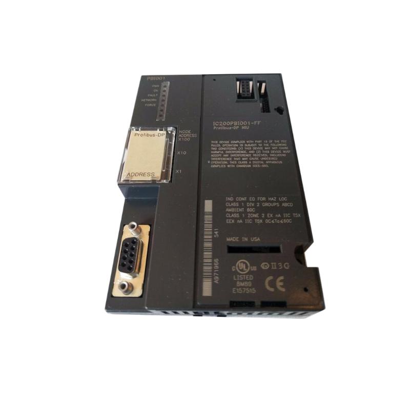
Product Overview
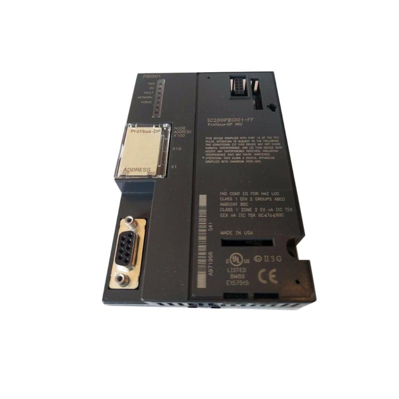
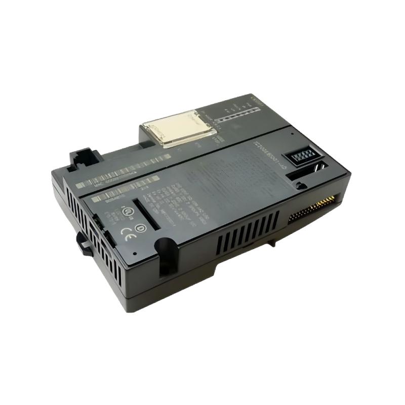
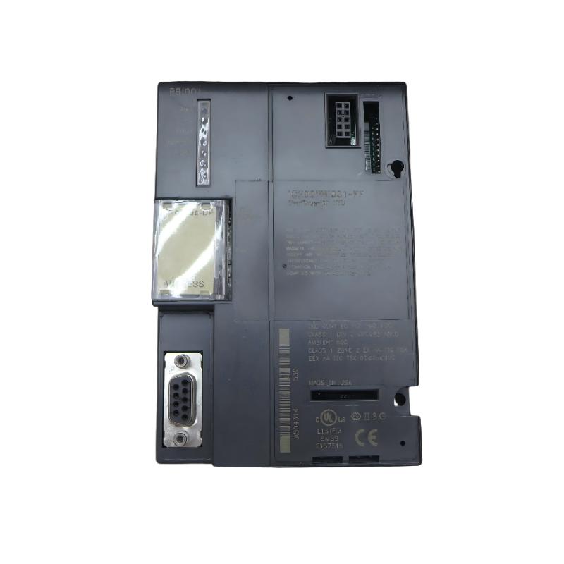
The GE IC200PBI001 VersaMax Fieldbus Network Interface Module is a communication interface component used in GE VersaMax distributed I/O systems. Its primary function is to provide the communication connection between the VersaMax I/O station and the associated fieldbus network, allowing a higher-level control system to exchange process data with distributed I/O modules.
In a typical industrial automation architecture, the controller or fieldbus master communicates with remote VersaMax I/O stations through a network. The IC200PBI001 acts as the network interface at the VersaMax station, managing the exchange of I/O data between the fieldbus and local I/O modules.
The module is therefore different from a conventional digital input or output module. Instead of directly controlling a field device, it provides the communication path through which input and output data can be exchanged between the control system and the local I/O station.
The supplied product information is:
- Manufacturer: GE
- Product Family: VersaMax
- Model: IC200PBI001
- Product Type: Fieldbus Network Interface Module
- Dimensions: 110 × 66.8 × 50 mm
- Weight: 0.132 kg
- Application: Distributed I/O and Industrial Automation
- Primary Function: Fieldbus Communication Interface
The exact fieldbus protocol, network addressing method, connector pinout, supported baud rates, diagnostic functions, termination requirements, and configuration parameters should be confirmed for the specific IC200PBI001 installation before commissioning.
Technical Specifications
| Parameter | Specification |
|---|---|
| Manufacturer | GE |
| Product Family | VersaMax |
| Model | IC200PBI001 |
| Product Type | Fieldbus Network Interface Module |
| Main Function | Network Communication |
| System Type | Distributed I/O |
| Application | Industrial Automation |
| Dimensions | 110 × 66.8 × 50 mm |
| Weight | 0.132 kg |
| Installation | VersaMax Modular I/O System |
| Interface | VersaMax I/O Backplane |
| Network Role | Fieldbus Network Interface |
| Communication Function | Exchange of I/O and Diagnostic Data |
| Typical Application | Remote I/O Station |
Function and Working Principle
The IC200PBI001 provides the communication interface between the fieldbus network and the local VersaMax I/O station.
A simplified architecture is:
Control System / Fieldbus Master
↓
Fieldbus Network
↓
IC200PBI001
↓
VersaMax Backplane
↓
Local I/O Modules
↓
Field Devices
The process begins when field devices generate signals.
For example:
- A sensor changes state.
- A temperature-related input changes.
- A limit switch becomes active.
- A machine position changes.
The corresponding input module receives the field signal and places the input data into the local I/O system.
The IC200PBI001 communicates this data over the fieldbus to the controlling system.
For output operations, the sequence works in the opposite direction:
PLC / Controller
↓
Fieldbus Network
↓
IC200PBI001
↓
VersaMax I/O Backplane
↓
Output Module
↓
Field Device
The controller sends an output command through the network. The IC200PBI001 receives the communication data and makes the relevant output information available to the local VersaMax I/O system.
This architecture allows I/O modules to be physically separated from the main controller while remaining part of the same automation system.
Role in Distributed I/O Systems
The IC200PBI001 is particularly important in distributed I/O architectures.
Instead of installing every I/O point inside the main control cabinet, distributed I/O allows I/O stations to be located closer to machines and process equipment.
A typical system may look like:
Main PLC
↓
Industrial Network
↓
IC200PBI001
↓
VersaMax I/O Station
↓
Sensors and Actuators
This arrangement can reduce long field wiring runs and simplify the organization of large automation systems.
The communication interface also allows the control system to exchange:
- Input status
- Output commands
- I/O data
- Network information
- Diagnostic information
- Station-related status
Typical Industrial Applications
Distributed Machine Automation
The IC200PBI001 can be used as the communication interface for remote I/O located near:
- Assembly machines
- Production lines
- Conveyor systems
- Packaging machines
- Material-handling equipment
- Automated production cells
The local I/O modules collect field information and communicate it to the main control system.
Conveyor Systems
Distributed I/O can be useful on large conveyor installations where sensors and actuators are physically distributed along a production line.
The local VersaMax station may connect:
- Proximity sensors
- Photoelectric sensors
- Limit switches
- Solenoid valves
- Motor-control interfaces
- Stack lights
- Alarm circuits
The IC200PBI001 provides the network interface for transferring this I/O information to the control system.
Packaging Equipment
Packaging machines may require I/O at several physical locations.
A distributed architecture can place remote I/O close to:
- Pneumatic valves
- Product sensors
- Position switches
- Clamping mechanisms
- Machine indicators
- Auxiliary actuators
The communication interface connects this local I/O station with the main control architecture.
Process Automation
Distributed I/O is frequently useful when process equipment is physically separated from the main control cabinet.
Potential applications include:
- Valve stations
- Pump systems
- Utility systems
- Equipment skids
- Process instrumentation
- Alarm interfaces
The IC200PBI001 can provide the network communication path for the associated local I/O.
Installation Guide
1. Verify the Product
Before installation, verify the module identification:
GE IC200PBI001
Inspect the module for:
- Cracked housing
- Damaged connectors
- Bent connector pins
- Physical deformation
- Broken mounting features
- Contamination
- Signs of overheating
- Corrosion
Do not install a visibly damaged module.
2. Inspect the VersaMax Carrier
The IC200PBI001 must be correctly integrated into the VersaMax I/O architecture.
Inspect:
- Carrier condition
- Backplane connector
- Module position
- Adjacent modules
- Mechanical locking features
- Grounding arrangements
- Associated I/O modules
A poor carrier connection can cause communication failures that appear to be network problems.
3. Plan the Network Installation
Before connecting the fieldbus, identify:
- Network topology
- Node or station address
- Network master
- Communication parameters
- Cable type
- Connector type
- Network termination
- Shielding requirements
- Maximum network length
- Number of network devices
Network planning should be completed before commissioning.
4. Install the Module
Align the IC200PBI001 with the appropriate carrier position.
Carefully engage the module.
Verify:
- Correct orientation
- Connector alignment
- Complete seating
- Secure locking
Do not force the module into the carrier.
5. Connect the Fieldbus
Connect the network cable according to the approved system wiring diagram.
Pay attention to:
- Correct connector
- Signal conductors
- Shielding
- Grounding
- Network polarity where applicable
- Termination
- Cable routing
Incorrect network wiring can prevent the entire remote I/O station from communicating.
6. Check Network Addressing
If the system requires a station or node address, verify that the address assigned to the IC200PBI001 does not conflict with another device.
Duplicate network addresses can cause communication problems and unpredictable network behavior.
7. Verify the Local I/O Configuration
Confirm that the I/O modules installed behind the network interface match the intended system configuration.
Check:
- Module order
- Module type
- Number of modules
- I/O addressing
- Configuration parameters
- Expected data size
A network interface can communicate correctly while the controller still reports an I/O configuration problem.
8. Verify Power
Check the applicable power sources for:
- Network interface
- VersaMax carrier
- I/O modules
- Field devices
- External network equipment
A missing local supply can cause the station to appear offline even when the network itself is functioning normally.
Commissioning Procedure
Step 1 — Mechanical Inspection
Verify that the IC200PBI001 is correctly seated.
Step 2 — Network Wiring Inspection
Check network conductors, connectors, shielding, and termination.
Step 3 — Address Verification
Confirm the station address and eliminate duplicate addresses.
Step 4 — Local I/O Verification
Confirm that all expected VersaMax modules are installed correctly.
Step 5 — Power Verification
Check the applicable control and I/O power supplies.
Step 6 — Network Startup
Energize the system according to the approved commissioning procedure.
Step 7 — Communication Verification
Confirm that the fieldbus master detects the remote I/O station.
Step 8 — I/O Data Test
Verify that input data reaches the controller correctly.
Step 9 — Output Test
Send controlled output commands and confirm that the local output modules respond.
Step 10 — Diagnostic Test
Check for communication errors, configuration faults, or station-related diagnostic conditions.
Step 11 — Process Test
Operate the complete machine or process and verify stable communication.
Troubleshooting Guide
Problem 1: IC200PBI001 Station Is Offline
Possible causes include:
- Loss of power
- Network cable problem
- Incorrect network address
- Network termination problem
- Connector problem
- Fieldbus configuration error
- Carrier connection problem
- Module failure
Recommended Checks
- Check module installation.
- Verify power.
- Inspect the network connector.
- Check network cable continuity.
- Verify the station address.
- Check network termination.
- Review controller diagnostics.
- Inspect the local I/O configuration.
Problem 2: Network Interface Is Powered but Communication Is Unstable
Possible causes include:
- Poor cable connection
- Electrical interference
- Incorrect termination
- Shielding problem
- Grounding problem
- Network overload
- Duplicate address
- Network configuration error
Start by checking the physical network layer before changing software configuration.
Problem 3: Controller Cannot Detect the Remote I/O Station
Check:
- Network address
- Fieldbus configuration
- Network cable
- Connector
- Power
- Network master status
- Local I/O configuration
- Communication parameters
If the controller cannot detect the station at all, focus first on the network path and station configuration.
Problem 4: Controller Detects the Station but Reports I/O Errors
This condition may indicate a local configuration problem.
Check:
- Module order
- Installed module types
- I/O configuration
- Module seating
- Backplane connection
- Local power
- Expected I/O data size
The network interface itself may be functioning correctly while a downstream I/O module is causing the diagnostic condition.
Problem 5: Input Data Is Not Updating
If the remote station communicates but an input value does not change, investigate:
- Input module
- Sensor
- Field wiring
- Input power
- I/O addressing
- Local backplane
- Configuration
Follow the signal path:
Sensor → Input Module → VersaMax Backplane → IC200PBI001 → Fieldbus → Controller
Problem 6: Output Command Reaches the Station but Field Device Does Not Operate
Trace the opposite direction:
Controller → Fieldbus → IC200PBI001 → Backplane → Output Module → Wiring → Field Device
Check each stage.
Potential causes include:
- Output module problem
- Field wiring fault
- Missing field power
- Failed actuator
- Incorrect output address
- Configuration problem
Problem 7: Communication Drops Intermittently
Intermittent network communication should be investigated systematically.
Check:
- Cable condition
- Connector condition
- Shielding
- Grounding
- Termination
- Electrical noise
- Network topology
- Power stability
- Mechanical vibration
An intermittent network fault may be caused by a physical connection rather than a software problem.
Problem 8: Communication Fails After Adding Another I/O Module
Possible causes include:
- Incorrect module configuration
- Improper module seating
- Carrier limitation
- Power capacity issue
- I/O configuration mismatch
- Incorrect module order
Verify the complete local I/O station configuration.
Problem 9: Replacement IC200PBI001 Does Not Correct the Fault
If replacing the module does not resolve the communication problem, investigate:
- Network cable
- Network master
- Station address
- Termination
- Power supply
- Carrier
- Local I/O configuration
- Network configuration
Repeated replacement of the communication interface without testing the network infrastructure can result in unnecessary maintenance.
Network Troubleshooting Strategy
A structured diagnostic approach is recommended.
Stage 1 — Power
Confirm that the network interface and local I/O station have the required power.
↓
Stage 2 — Physical Network
Check cable, connector, shielding, grounding, and termination.
↓
Stage 3 — Addressing
Verify station and node addressing.
↓
Stage 4 — Communication Configuration
Verify network parameters and master configuration.
↓
Stage 5 — IC200PBI001
Determine whether the network interface is operating normally.
↓
Stage 6 — Local Backplane
Verify communication between the interface module and local I/O modules.
↓
Stage 7 — I/O Configuration
Confirm that the installed modules match the configured station.
↓
Stage 8 — Field Devices
Check sensors, actuators, and field wiring.
This process helps distinguish:
Power Problem
from
Network Wiring Problem
from
Addressing Problem
from
Configuration Problem
from
Interface Module Problem
from
Backplane Problem
from
I/O Module Problem
from
Field Device Problem
Network Installation Best Practices
Keep Network Wiring Away From High-Noise Circuits
Where practical, separate communication cables from:
- Motor power cables
- Variable-frequency drive cables
- High-current feeders
- Large contactors
- Transformer wiring
Electrical noise can affect industrial communication networks.
Maintain Proper Shielding
Where shielded network cable is specified, maintain the shielding arrangement throughout the network installation.
Improper shielding can increase susceptibility to electrical interference.
Verify Network Termination
Where the network protocol requires termination, termination must be installed at the correct locations.
Incorrect termination can produce:
- Communication errors
- Intermittent network faults
- Station dropouts
- Reduced communication reliability
Avoid Duplicate Addresses
Every station requiring a unique network address must have a valid and unique address.
Two devices using the same address can cause serious communication problems.
Preventive Maintenance
| Inspection Item | Recommended Check |
|---|---|
| Module Housing | Inspect for physical damage |
| Module Seating | Verify secure installation |
| Carrier Connector | Check condition |
| Network Cable | Inspect for damage |
| Network Connector | Verify connection |
| Shielding | Check continuity and routing |
| Grounding | Verify approved arrangement |
| Termination | Check correct installation |
| Power Supply | Verify stability |
| Station Address | Confirm uniqueness |
| I/O Configuration | Compare installed vs configured modules |
| Diagnostics | Review recurring communication faults |
Preventive maintenance is especially valuable in environments with vibration, electrical noise, dust, humidity, or frequent equipment changes.
IC200PBI001 Troubleshooting Table
| Symptom | Possible Cause | Recommended Check |
|---|---|---|
| Station offline | Power/network/configuration | Check power, cable and address |
| Communication unstable | Noise/termination/cable | Inspect physical network |
| Controller cannot detect station | Address/configuration | Check network settings |
| Station detected but I/O fault | Local configuration | Check module order and I/O |
| Input data not updating | Sensor/input/wiring | Trace input signal path |
| Output command has no effect | Output/load/wiring | Trace output signal path |
| Communication drops intermittently | Cable/connector/noise | Inspect network infrastructure |
| Fault after adding I/O | Configuration/power/carrier | Check local station |
| Replacement does not help | External network fault | Check network and configuration |
Key Advantages
- GE VersaMax modular architecture
- Designed for distributed I/O applications
- Provides a fieldbus network interface
- Enables communication between remote I/O and the control system
- Supports centralized monitoring of distributed I/O
- Suitable for machine automation
- Suitable for process automation
- Helps reduce long field wiring runs
- Supports modular I/O station architectures
- Compact physical dimensions
- Dimensions of 110 × 66.8 × 50 mm
- Supplied weight of 0.132 kg
Technical FAQs
What is GE IC200PBI001?
The GE IC200PBI001 is a VersaMax Fieldbus Network Interface Module used to connect a VersaMax distributed I/O station to the associated industrial fieldbus network.
What is the main function of IC200PBI001?
Its primary function is to provide communication between the fieldbus network and the local VersaMax I/O modules.
Is IC200PBI001 an input module?
No. It is a network interface module, not a conventional discrete input or analog input module.
Is IC200PBI001 an output module?
No. It does not function as a conventional field output module. It provides the communication interface through which output data can be transferred to the local VersaMax I/O system.
What are the dimensions of IC200PBI001?
The supplied dimensions are:
110 × 66.8 × 50 mm
What is the weight of IC200PBI001?
The supplied product information specifies:
0.132 kg
Where is IC200PBI001 installed?
It is installed as part of a VersaMax modular I/O station and interfaces with the local I/O architecture and fieldbus network.
Why is the remote I/O station offline?
Possible causes include power loss, network wiring problems, connector issues, incorrect addressing, termination problems, configuration errors, carrier problems, or module failure.
Why does the controller detect the network interface but report I/O errors?
Check the local I/O configuration, module order, module seating, backplane connection, power supply, and configured I/O data.
Why does communication drop intermittently?
Possible causes include poor network connections, damaged cable, electrical interference, grounding or shielding problems, incorrect termination, unstable power, or network configuration issues.
Why does input data not reach the controller?
Trace the signal path from the field sensor through the input module, VersaMax backplane, IC200PBI001, fieldbus network, and controller. This helps identify where the data path is interrupted.
Why does an output command reach the station but the actuator does not respond?
Check the local output module, field wiring, field power, actuator, output address, and configuration.
Can electrical noise affect IC200PBI001 communication?
Yes. Industrial environments containing high-current switching equipment, motor drives, contactors, and other electrical noise sources can affect communication reliability if network installation and grounding practices are inadequate.
Should IC200PBI001 be replaced immediately after a communication fault?
No. First inspect power, network wiring, connectors, addressing, termination, configuration, carrier, and the network master.
How can I determine whether IC200PBI001 itself is faulty?
Verify power and network infrastructure first. If the cable, connector, addressing, termination, master configuration, carrier, and local I/O configuration are correct but the station still cannot communicate properly, the network interface module becomes a stronger suspect.
What if a replacement module has the same communication problem?
Check the external network infrastructure, configuration, station address, fieldbus master, power supply, carrier, and local I/O modules. Identical symptoms after replacement usually indicate that the problem may exist outside the interface module.
Conclusion
The GE IC200PBI001 VersaMax Fieldbus Network Interface Module provides the communication link between a VersaMax distributed I/O station and its associated fieldbus network. Rather than directly processing a physical sensor or actuator signal, it serves as the network gateway through which local I/O information is exchanged with the control system.
The supplied physical specifications are 110 × 66.8 × 50 mm, with a stated weight of 0.132 kg.
Proper installation requires correct carrier engagement, reliable network wiring, appropriate addressing, correct termination, stable power, and an accurate local I/O configuration. During commissioning, the network should first be tested at the communication level before individual input and output points are validated.