

ProductPRODUCT
Featured products
Contact Us
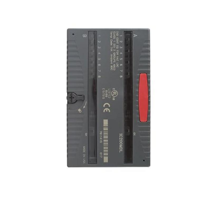
- GE
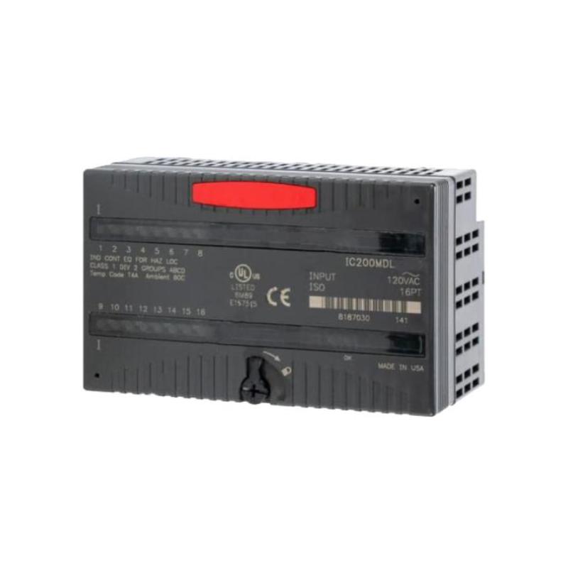
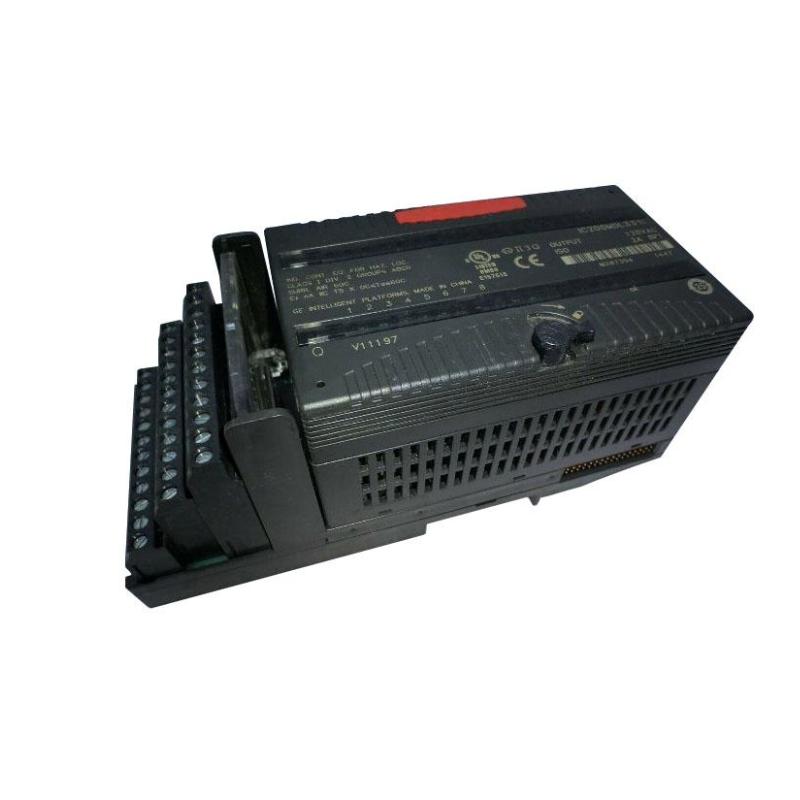
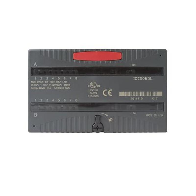
- IC200MDL331
- VersaMax Discrete Output Module
- USA
- 110 x 66.8 x 50 mm
- 0.45 kg
- Xiamen, China
- New & In Stock
- T/T, PayPal, Western Union
- 1 Year
- 1-3 Working Days
- DHL, UPS, TNT, FedEx and EMS.
- 24-Hour Service
- COO
- 46
Our advantage

Global Logistics
We have a 10-year logistics and express cooperation agreement, so our products can be shipped to any place in the world.

Brand new and original
Our products are imported in bulk from the place of origin. Because of the cooperative relationship, our products are all original and 100% new.

24-hour service
We provide 7*24 hours service to our customers. We will be there whenever you need us.

Price advantage
All our products are priced very favorably because we have our own warehouse and supply.
| Company Information | |||
| [email protected] | |||
| Mobile | +8615980777398 | ||
| +8615980777398 | |||
| 15980777398 |
Product Overview
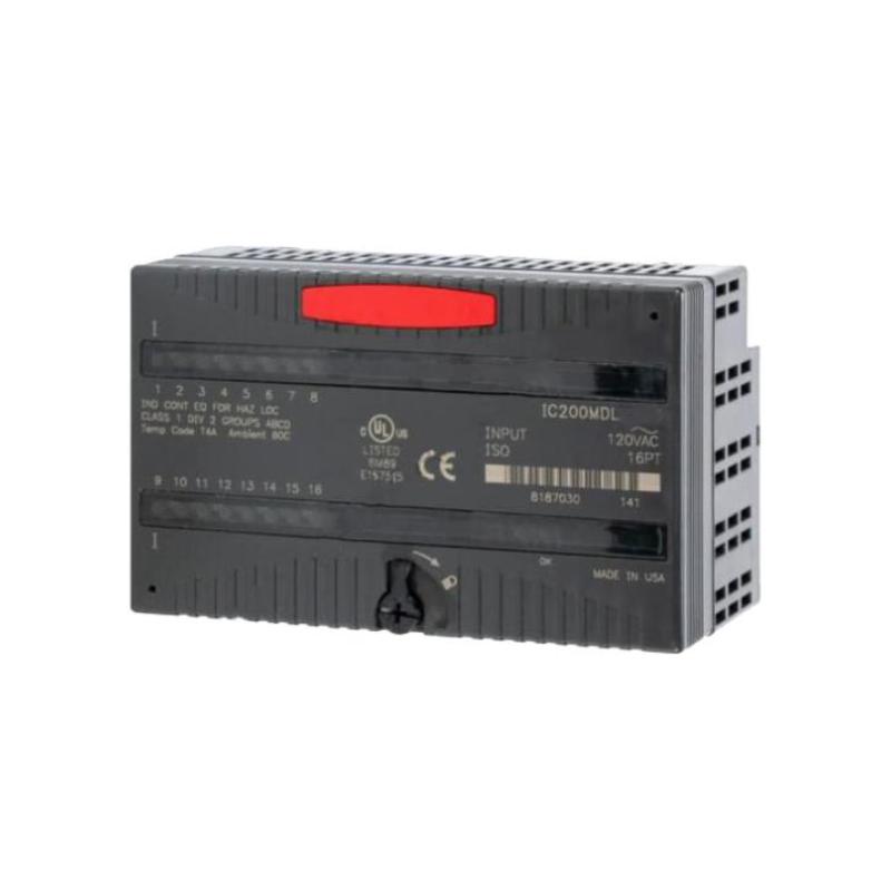
The GE IC200MDL331 VersaMax Discrete Output Module is a modular digital output component designed for industrial automation systems based on the GE VersaMax platform. It provides the interface between PLC control logic and external discrete field devices, allowing programmed output commands to be transferred to actuators and other binary loads.
In a typical automation system, the controller determines when a field device should be activated or deactivated. The output module then provides the corresponding electrical switching function. This architecture allows the PLC to control equipment such as relays, solenoid valves, contactors, indicators, alarms, and auxiliary control circuits.
The IC200MDL331 is intended to operate within a complete VersaMax I/O architecture. Its reliable operation depends not only on the module itself but also on the carrier, backplane, controller, field power supply, wiring, and connected load.
The supplied product information is:
- Manufacturer: GE
- Product Family: VersaMax
- Model: IC200MDL331
- Product Type: Discrete Output Module
- Dimensions: 110 × 66.8 × 50 mm
- Weight: 0.45 kg
- Application: Industrial Automation
- Primary Function: Discrete Output Signal Control
For installation, replacement, and commissioning, the actual electrical output specifications and connected-load requirements should be confirmed for the specific system configuration.
Technical Specifications
| Parameter | Specification |
|---|---|
| Manufacturer | GE |
| Product Family | VersaMax |
| Model | IC200MDL331 |
| Product Type | VersaMax Discrete Output Module |
| Signal Type | Digital / Discrete Output |
| Main Function | Field Device Control |
| System Architecture | Modular I/O |
| Application | Industrial Automation |
| Dimensions | 110 × 66.8 × 50 mm |
| Weight | 0.45 kg |
| Installation | VersaMax Modular I/O System |
| Interface | VersaMax I/O Backplane |
| Field Interface | Discrete Output Circuits |
| Typical Applications | Relays, Contactors, Solenoids, Indicators, Alarms |
The precise output voltage, current rating, switching behavior, channel arrangement, load restrictions, protection requirements, and terminal configuration should be verified before connecting field equipment.
Function and Working Principle
The IC200MDL331 receives discrete commands from the VersaMax controller and transfers those commands to external field circuits.
A simplified signal path is:
PLC Program
↓
VersaMax Controller
↓
I/O Backplane
↓
IC200MDL331
↓
Field Wiring
↓
Actuator / Load
When the PLC program turns an output ON, the controller sends the corresponding command to the output module. The appropriate output circuit then changes state, allowing the connected field device to operate.
When the PLC turns the output OFF, the output circuit returns to its inactive condition.
For example, a PLC may command a solenoid valve to open. The controller sends the output command to the IC200MDL331, and the module switches the corresponding field circuit. The solenoid responds and changes the process condition.
The module therefore provides the physical link between software control logic and the field device.
Role in Industrial Control Systems
The IC200MDL331 can be integrated into a complete automation signal chain:
Sensors
↓
Input Modules
↓
VersaMax Controller
↓
PLC Logic
↓
IC200MDL331
↓
Actuators
↓
Industrial Process
The input modules provide information about the machine or process, while the output module executes the controller’s commands.
Typical functions include:
- Equipment start commands
- Valve actuation
- Relay control
- Contactor control
- Machine sequencing
- Alarm activation
- Indicator control
- Interlock-related outputs
- Auxiliary equipment control
Typical Industrial Applications
Machine Automation
The IC200MDL331 can be incorporated into machine-control systems for operating:
- Solenoid valves
- Control relays
- Contactors
- Pneumatic actuators
- Indicator lights
- Alarm devices
- Auxiliary control circuits
Conveyor Systems
Possible applications include:
- Conveyor-control relays
- Diverter solenoids
- Motor-control interfaces
- Stack lights
- Alarm outputs
- Auxiliary equipment
The controller can sequence outputs based on feedback from discrete input modules.
Packaging Machinery
Discrete outputs can control:
- Pneumatic valves
- Clamping devices
- Product diverters
- Machine indicators
- Alarm circuits
- Auxiliary relays
Correct output sequencing is particularly important in packaging machines where several operations must occur in a precise order.
Pump and Fan Systems
The module may be incorporated into control circuits for:
- Pump starters
- Fan-control interfaces
- Equipment enable signals
- Auxiliary relays
- Alarm outputs
- Status-related control circuits
Dedicated motor-control equipment should be used where required by the motor’s electrical characteristics.
Process Automation
Possible applications include:
- Valve-control signals
- Pump enable commands
- Alarm activation
- Equipment permissives
- Auxiliary control circuits
- Process sequence commands
Installation Guide
1. Verify the Module
Before installation, confirm the product identification:
GE IC200MDL331
Inspect the module for:
- Cracks
- Deformation
- Damaged connectors
- Broken locking features
- Contamination
- Signs of overheating
Do not install a module with visible physical damage.
2. Inspect the Carrier
Before installation, inspect the VersaMax carrier and module interface.
Check:
- Carrier condition
- Backplane connector
- Mounting location
- Adjacent modules
- Terminal assembly
- Power connections
A damaged carrier can cause output faults that may be incorrectly attributed to the module.
3. Apply Electrical Safety Procedures
Follow the facility’s approved electrical isolation procedure before installation or removal.
Unless the installed system specifically supports live replacement, power should be removed before servicing.
Connected machinery should also be placed into a safe condition.
4. Install the Module
Align the IC200MDL331 with its assigned carrier position.
Carefully engage the module.
Confirm:
- Correct orientation
- Connector alignment
- Full seating
- Secure locking
Never force the module into the carrier.
If it does not install smoothly, inspect the connector and carrier before continuing.
5. Connect Field Loads
Connect field devices according to the approved electrical drawings.
Typical loads may include:
- Relays
- Contactors
- Solenoid valves
- Indicators
- Alarm devices
- Auxiliary control circuits
Before connecting a load, verify that its electrical requirements are compatible with the output circuit.
6. Verify Output Wiring
Inspect:
- Terminal assignments
- Output conductors
- Common connections
- External power
- Load wiring
- Protective devices
- Cable insulation
Incorrect wiring can result in an inactive output, unintended activation, or damage to the connected circuit.
7. Check Load Compatibility
Before commissioning, consider the actual characteristics of every connected load.
Check:
- Operating voltage
- Normal current
- Inrush current
- Load type
- Switching frequency
- Inductive characteristics
- Required suppression
Special care should be taken with coils, contactors, and solenoids because inductive loads can generate switching transients.
Commissioning Procedure
Step 1 — Mechanical Inspection
Confirm that the IC200MDL331 is fully seated.
Step 2 — Wiring Verification
Compare all field wiring with the electrical drawings.
Step 3 — Load Verification
Confirm that each connected load is suitable for the output circuit.
Step 4 — Power Verification
Check field power and common connections.
Step 5 — System Energization
Restore power according to the approved commissioning procedure.
Step 6 — Controller Recognition
Verify that the controller recognizes the installed module.
Step 7 — Individual Output Testing
Activate individual outputs using the approved test procedure.
Step 8 — Field Device Testing
Verify that each connected device responds correctly.
Step 9 — Interlock Testing
Confirm that outputs operate only when the required permissive conditions are satisfied.
Step 10 — Sequence Testing
Run the machine or process through its intended sequence and verify all output functions.
Troubleshooting Guide
Problem 1: IC200MDL331 Is Not Recognized
Possible causes include:
- Incorrect installation
- Poor connector engagement
- Carrier fault
- Configuration problem
- Power issue
- Module fault
Recommended Checks
- Check module seating.
- Inspect the carrier connector.
- Check available module diagnostics.
- Review controller diagnostics.
- Verify system configuration.
- Check power.
- Inspect adjacent modules.
If the problem persists, investigate the carrier and backplane.
Problem 2: PLC Commands the Output but the Load Does Not Operate
Possible causes include:
- Open field wiring
- Missing external power
- Incorrect terminal connection
- Failed load
- Common-circuit problem
- Output-channel problem
- Open protective device
Trace the complete circuit:
PLC Command → Output Module → Field Wiring → Power → Load
This prevents unnecessary module replacement.
Problem 3: Output Remains OFF
If the PLC indicates that the output should be ON but the physical load remains inactive, check:
- PLC logic
- Output address
- Controller status
- Module status
- Field power
- Wiring
- Terminal connections
- Load condition
- Output channel
A programming or addressing problem can produce symptoms identical to a hardware failure.
Problem 4: Output Remains ON
Possible causes include:
- PLC logic
- Incorrect output mapping
- Wiring error
- Output-channel problem
- External circuit condition
First determine whether the PLC is still commanding the output.
If the PLC command is OFF but the physical output remains active, investigate the output circuit and module.
Problem 5: Output Operates Intermittently
Potential causes include:
- Loose terminal
- Unstable field power
- Damaged load
- Voltage drop
- Connector problem
- Electrical interference
- Mechanical problems with the actuator
Test the circuit under actual operating conditions.
Problem 6: Output Becomes Unstable When a Load Is Switched
If the problem appears when a relay, contactor, or solenoid is energized or de-energized, investigate:
- Inductive load characteristics
- Suppression
- Field wiring
- Power stability
- Coil condition
- Excessive load
The problem may originate in the field circuit rather than in the output module.
Problem 7: Multiple Outputs Stop Operating
When several outputs fail simultaneously, investigate common components.
Check:
- Field power
- Common wiring
- Controller status
- Carrier
- Backplane
- Shared protective devices
- Configuration
A common supply or communication problem can affect multiple channels simultaneously.
Problem 8: Replacement Module Shows the Same Fault
If replacing the IC200MDL331 does not correct the fault, investigate:
- PLC program
- Output addressing
- Field wiring
- Field power
- Load
- Carrier
- Backplane
- Common connections
Repeated module replacement without examining the external circuit is unlikely to resolve an external fault.
Systematic Fault Diagnosis
A structured output diagnostic process should follow the command from the PLC toward the load.
Stage 1 — PLC Program
Confirm that the required output command is generated.
↓
Stage 2 — Controller
Confirm that the controller processes the command correctly.
↓
Stage 3 — Backplane
Verify communication between the controller and output module.
↓
Stage 4 — IC200MDL331
Determine whether the corresponding output channel responds.
↓
Stage 5 — Field Wiring
Check continuity and terminal connections.
↓
Stage 6 — Field Power
Confirm the external load supply.
↓
Stage 7 — Load
Verify that the actuator operates correctly.
This approach helps distinguish:
- PLC logic problems
- Addressing problems
- Module problems
- Wiring faults
- Power-supply faults
- Load failures
Inductive Load Considerations
Many discrete output applications involve inductive devices such as:
- Relay coils
- Contactors
- Solenoid valves
- Electromagnetic actuators
When these devices are switched, stored energy can generate transient electrical effects.
Therefore, the field circuit should be designed with appropriate protection based on the load type.
Important considerations include:
- Operating voltage
- Load current
- Inrush current
- Coil characteristics
- Switching frequency
- Suppression
- External protection
The correct protection method depends on the actual electrical characteristics of the connected load.
Preventive Maintenance
| Inspection Item | Recommended Check |
|---|---|
| Module Housing | Inspect for physical damage |
| Module Seating | Verify secure installation |
| Connectors | Check for contamination |
| Terminals | Check connection integrity |
| Field Wiring | Inspect insulation and routing |
| Load Devices | Verify operating condition |
| Field Power | Check stability |
| Carrier | Inspect mechanical condition |
| Cabinet | Check dust and moisture |
| Inductive Loads | Check protection |
| Diagnostics | Review recurring faults |
Preventive inspection is particularly useful in systems exposed to vibration, frequent switching, high temperatures, dust, or electrical interference.
Wiring Best Practices
Separate Control and Power Wiring
Keep output/control wiring away from high-power conductors wherever practical.
Pay particular attention around:
- Motor cables
- VFD cables
- Transformer wiring
- Large contactors
- High-current feeders
Secure All Terminations
Loose connections can result in:
- Intermittent loads
- Voltage drops
- Heating
- Random equipment operation
- Output faults
Verify Common Connections
A shared common or field supply problem can disable several outputs simultaneously.
Use Appropriate Load Protection
Relay coils, contactors, and solenoids may require suitable suppression to reduce switching transients.
IC200MDL331 Troubleshooting Table
| Symptom | Possible Cause | Recommended Check |
|---|---|---|
| Module not recognized | Installation/configuration | Check module and carrier |
| Output command but no load | Wiring/power/load problem | Trace complete circuit |
| Output remains OFF | Logic/addressing/wiring | Check PLC and field circuit |
| Output remains ON | Logic/wiring/channel fault | Compare command and physical state |
| Intermittent operation | Loose connection/power | Inspect field circuit |
| Fault during switching | Inductive transient | Check load and protection |
| Several outputs fail | Shared power/common | Check supply and common |
| Replacement does not help | External fault | Check PLC, wiring, load and carrier |
Key Advantages
- GE VersaMax modular I/O architecture
- Designed for discrete output applications
- Suitable for industrial automation
- Provides a controller-to-field interface
- Suitable for relay and actuator control
- Supports machine sequencing
- Suitable for process-control applications
- Compact modular construction
- Supports structured troubleshooting
- Suitable for industrial control cabinets
- Supplied dimensions of 110 × 66.8 × 50 mm
- Supplied weight of 0.45 kg
Technical FAQs
What is GE IC200MDL331?
The GE IC200MDL331 is a VersaMax discrete output module designed to provide digital control signals to suitable external field devices.
What does IC200MDL331 do?
It receives output commands from the VersaMax controller and provides corresponding discrete output states to connected field circuits.
What devices can be controlled?
Depending on the actual electrical specifications and system design, applications can include:
- Relays
- Contactors
- Solenoid valves
- Indicators
- Alarms
- Auxiliary control devices
What are the dimensions of IC200MDL331?
The supplied dimensions are:
110 × 66.8 × 50 mm
What is the weight of IC200MDL331?
The supplied product information specifies:
0.45 kg
Is IC200MDL331 a standalone PLC?
No. It is a modular output component that operates as part of a VersaMax control system.
Why does an output command not activate the field device?
Check the PLC program, output address, controller status, module status, field power, terminal connections, wiring, and load.
Why does an output remain OFF?
Possible causes include incorrect PLC logic, incorrect output addressing, missing field power, wiring problems, or an output-channel fault.
Why does an output remain ON?
First check whether the PLC is still commanding the output. If the command is OFF but the physical output remains active, inspect the wiring and output channel.
Why does a load operate intermittently?
Check loose terminals, unstable power, voltage drop, connector condition, damaged loads, and electrical interference.
Can a solenoid or contactor affect the output module?
Yes. Inductive loads can produce switching transients, so suitable circuit protection should be considered for the actual load.
Why do several outputs fail simultaneously?
Check shared power, common wiring, controller operation, carrier condition, backplane communication, and shared protection.
Should I replace IC200MDL331 immediately after an output failure?
No. First verify the PLC command, output addressing, wiring, field power, and connected load.
How can I determine whether the output channel has failed?
Confirm that the PLC is commanding the output, verify the field wiring and power, and confirm that the connected load is functional. If all external conditions are correct but the output channel does not respond, the module becomes a stronger suspect.
What if the replacement module has exactly the same fault?
Check the PLC program, field wiring, power supply, load, carrier, backplane, and output configuration. A repeated fault after replacement usually indicates an external problem.
Conclusion
The GE IC200MDL331 VersaMax Discrete Output Module provides a modular interface between PLC control logic and discrete industrial field devices. It can be incorporated into machine automation, conveyor systems, packaging equipment, pump and fan control, process automation, and other applications requiring discrete output control.
The supplied physical specifications are 110 × 66.8 × 50 mm and 0.45 kg. As a VersaMax I/O component, it should be installed as part of the appropriate controller, carrier, backplane, power, and field-device architecture.
Successful commissioning requires correct module installation, proper field wiring, suitable load selection, reliable power connections, and appropriate consideration of inductive loads. During commissioning, outputs should be tested individually and the physical response of each field device should be compared with the corresponding PLC command.
For fault diagnosis, the most effective method is to trace the complete path from PLC logic → controller → backplane → IC200MDL331 → field wiring → field power → load. This approach helps identify whether a problem originates in the control program, output module, wiring, power supply, or connected equipment.