

ProductPRODUCT
Featured products








Contact Us
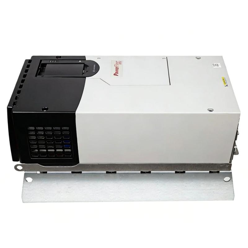
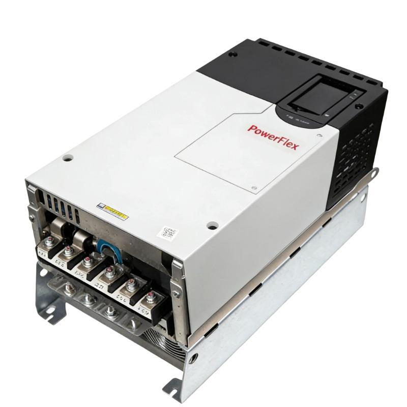
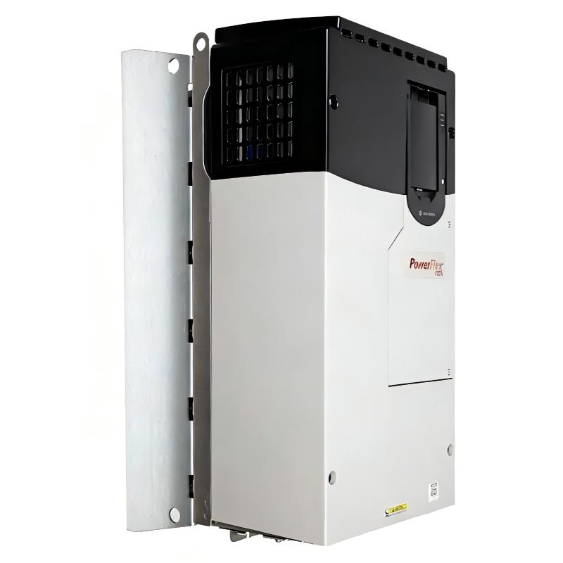
- Allen Bradley
- 20F1ANF020AA0NNNNN
- PowerFlex AC Drive
- USA
- 665.5 × 308 × 346.4 mm
- 38.6kg
- Xiamen, China
- New & In Stock
- T/T, PayPal, Western Union
- 1 Year
- 1-3 Working Days
- DHL, UPS, TNT, FedEx and EMS.
- 24-Hour Service
- COO
- 52
Our advantage

Global Logistics
We have a 10-year logistics and express cooperation agreement, so our products can be shipped to any place in the world.

Brand new and original
Our products are imported in bulk from the place of origin. Because of the cooperative relationship, our products are all original and 100% new.

24-hour service
We provide 7*24 hours service to our customers. We will be there whenever you need us.

Price advantage
All our products are priced very favorably because we have our own warehouse and supply.
| Company Information | |||
| [email protected] | |||
| Mobile | +8615980777398 | ||
| +8615980777398 | |||
| 15980777398 |
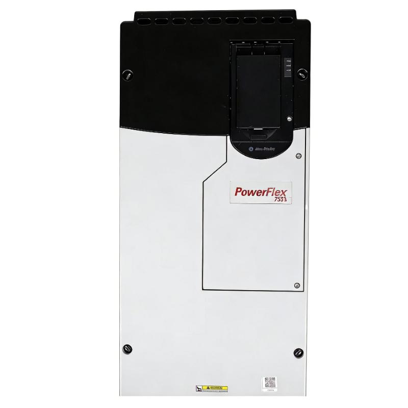
Allen-Bradley 20F1ANF020AA0NNNNN — Detailed Product Overview, Technical Specifications, Applications, Advantages and Related Models
1. Product Overview
The 20F1ANF020AA0NNNNN is an industrial AC variable-frequency drive belonging to the Allen-Bradley PowerFlex 753 series.
It is designed for controlling three-phase AC motors in industrial machinery, production equipment, process systems, pumps, fans, conveyors, mixers and other applications where adjustable motor speed and controlled motor operation are required.
This particular configuration is a 690 VAC, three-phase, 20 A drive, with a 15 kW Normal Duty rating and an 11 kW Heavy Duty rating.
The drive uses a Frame 6 open-type construction with forced-air cooling and embedded I/O. It is configured for AC input with precharge and no DC terminals.
One particularly important feature of this specific catalog number is its internal dynamic-braking transistor.
The model also has a specific filtering and common-mode configuration represented by the catalog-number option structure. Because the complete catalog number contains several configuration characters, it should be treated as a complete product identifier rather than simply as a 20 A PowerFlex 753 drive.
The drive is intended primarily for industrial cabinet installation and is suitable for applications where the motor needs to operate at variable speeds rather than simply being switched on and off at a fixed speed.
2. Brand and Product Series
| Item | Specification |
|---|---|
| Brand | Allen-Bradley |
| Product Family | PowerFlex |
| Product Series | PowerFlex 753 |
| Product Type | AC Variable Frequency Drive |
| Catalog Number | 20F1ANF020AA0NNNNN |
| Drive Type | Air-Cooled AC Drive |
| Voltage Class | 690 VAC |
| Input Phase | Three Phase |
| Output Phase | Three Phase |
| Rated Output Current | 20 A |
| Normal Duty Rating | 15 kW |
| Heavy Duty Rating | 11 kW |
| Frame Size | Frame 6 |
| Enclosure | Open Type |
| Cooling | Forced Air |
| Input Type | AC Input with Precharge, No DC Terminals |
| Dynamic Braking | Internal Dynamic-Braking Transistor |
| Embedded I/O | Yes |
| Interface | Blank / Configuration Dependent |
| Application Category | Industrial Motor Speed Control |
The product hierarchy can be summarized as:
Allen-Bradley → PowerFlex → PowerFlex 753 → 20F1ANF020AA0NNNNN
The PowerFlex 753 platform is intended for general-purpose industrial motor-control applications where reliable variable-speed operation and integration with a larger automation system are important.
3. Main Technical Specifications
| Parameter | Specification |
|---|---|
| Model | 20F1ANF020AA0NNNNN |
| Brand | Allen-Bradley |
| Series | PowerFlex 753 |
| Product Type | Industrial AC Variable Frequency Drive |
| Input Voltage | 690 VAC |
| Input Frequency | 50/60 Hz |
| Input Phase | 3 Phase |
| Output Phase | 3 Phase |
| Rated Output Current | 20 A |
| Normal Duty Continuous Current | 20 A |
| Normal Duty 1-Minute Current | 22 A |
| Normal Duty 3-Second Current | 30 A |
| Normal Duty Power | 15 kW |
| Heavy Duty Continuous Current | 15 A |
| Heavy Duty 1-Minute Current | 22.5 A |
| Heavy Duty 3-Second Current | 30 A |
| Heavy Duty Power | 11 kW |
| Frame Size | Frame 6 |
| Enclosure | IP00/IP20, Open Type |
| Cooling Method | Forced Air |
| Input Configuration | AC Input with Precharge |
| DC Terminals | None |
| Dynamic Braking | Internal Dynamic-Braking Transistor |
| Embedded I/O | Yes |
| Motor Control | V/Hz, Sensorless Vector, Vector Control |
| Mounting | Cabinet / Panel |
| Approx. Height | 665.5 mm |
| Approx. Width | 308 mm |
| Approx. Depth | 346.4 mm |
| Approx. Dimensions | 665.5 × 308 × 346.4 mm |
| Approx. Weight | 38.6 kg |
| Main Application | Industrial Three-Phase AC Motor Control |
The 20 A continuous current rating is one of the most important specifications of this model.
The Normal Duty power rating is 15 kW, while the Heavy Duty rating is 11 kW.
This distinction is important because a 15 kW motor may be suitable in an appropriate Normal Duty application, while a demanding constant-torque application may need to be evaluated against the lower Heavy Duty rating.
4. Catalog Number Interpretation
The complete catalog number is:
20F1ANF020AA0NNNNN
Understanding the catalog number is useful when comparing this model with other PowerFlex 753 configurations.
| Catalog Section | General Meaning | Configuration |
|---|---|---|
| 20F | Product family | PowerFlex 753 |
| 1 | Series / reserved designation | Standard configuration |
| A | Input type | AC input with precharge, no DC terminals |
| N | Enclosure | Open type |
| F | Voltage class | 690 VAC |
| 020 | Current rating | 20 A |
| A | Interface / configuration option | Specific option configuration |
| A | Dynamic-braking option | Internal braking transistor installed |
| 0 | Reserved / configuration | Standard |
| NNNNN | Additional configuration positions | Standard configuration |
The F voltage designation is especially important because it identifies the 690 VAC class.
The 020 portion identifies the 20 A current class.
The A braking designation indicates that the drive is equipped with an internal dynamic-braking transistor.
This is one of the main differences between this model and the corresponding no-braking-transistor versions.
5. 690 VAC Three-Phase Drive
The drive is designed for the 690 VAC class.
This makes it particularly suitable for industrial systems using higher-voltage three-phase motors.
Compared with lower-voltage motor systems, 690 VAC installations are often used for larger industrial motors and equipment where reducing current can be advantageous.
A 690 VAC drive can help reduce current for a given power level compared with an equivalent lower-voltage system.
However, the motor, cables, switchgear, insulation system and overall electrical installation must all be suitable for the voltage class.
The drive should therefore be selected together with the motor and electrical system rather than independently.
6. 20 A Output Current
The 20 A output rating places this model above the 12 A and 15 A versions in the same 690 VAC PowerFlex 753 range.
This provides additional capacity for larger motors.
The drive can therefore be considered when the motor’s operating current is greater than the practical capacity of a 12 A or 15 A model.
The actual motor nameplate current remains the most important factor when determining whether the drive is appropriately sized.
7. Normal Duty Rating — 15 kW
The Normal Duty rating is:
15 kW
This rating is appropriate for applications where the motor load is relatively moderate or variable.
Typical examples include:
- Centrifugal pumps
- Industrial fans
- Blowers
- Ventilation systems
- Cooling equipment
- Variable-torque machinery
- General industrial machinery
The 15 kW rating provides a useful capacity for medium-power industrial motor applications.
8. Heavy Duty Rating — 11 kW
The Heavy Duty rating is:
11 kW
Heavy Duty applications typically require greater torque capability and greater overload capacity.
Examples can include:
- Conveyors
- Mixers
- Material-handling equipment
- Constant-torque machinery
- High-inertia machinery
- Production machinery
- Equipment with frequent acceleration
Therefore, the drive should not automatically be selected for an 15 kW motor simply because the nameplate power is 15 kW.
If the application is a demanding constant-torque load, the 11 kW Heavy Duty rating may be the more relevant value.
9. Normal Duty and Heavy Duty Comparison
| Parameter | Normal Duty | Heavy Duty |
|---|---|---|
| Continuous Current | 20 A | 15 A |
| 1-Minute Current | 22 A | 22.5 A |
| 3-Second Current | 30 A | 30 A |
| Power Rating | 15 kW | 11 kW |
| Typical Load | Variable Torque | Constant Torque |
| Typical Equipment | Pumps, fans, blowers | Conveyors, mixers |
| Selection Basis | Motor current + duty | Motor current + duty |
The difference between Normal Duty and Heavy Duty is one of the most important considerations when selecting this model.
The same drive can therefore be suitable for a 15 kW motor in one application but may need to be downsized in another application where the load demands higher continuous torque.
10. Internal Dynamic-Braking Transistor
One of the main features of 20F1ANF020AA0NNNNN is its internal dynamic-braking transistor.
Dynamic braking is useful when the motor and load need to decelerate relatively quickly.
During deceleration, the rotating motor and load can return energy to the drive’s DC bus.
This regenerative energy causes the DC-bus voltage to rise.
A dynamic-braking system provides a controlled method of dissipating this energy through an appropriate braking resistor.
This can be particularly useful for:
- Conveyors
- High-inertia machines
- Centrifuges
- Mixers
- Material-handling systems
- Rapid-stop applications
- Machinery requiring frequent deceleration
The presence of the internal braking transistor makes this configuration particularly attractive when dynamic braking is required.
11. Dynamic Braking Compared With No-Braking Configurations
| Feature | 20F1ANF020AA0NNNNN | No-Braking Version |
|---|---|---|
| Rated Current | 20 A | 20 A class |
| Normal Duty | 15 kW | 15 kW |
| Heavy Duty | 11 kW | 11 kW |
| Dynamic-Braking Transistor | Yes | No |
| High-Inertia Application | More suitable | Additional braking solution may be required |
| Rapid Deceleration | Better suited | Requires additional evaluation |
| Braking Resistor | May be used with suitable configuration | Requires external braking arrangement where applicable |
| Main Advantage | Integrated braking capability | Simpler configuration |
The internal braking transistor does not mean that every application automatically requires a braking resistor.
The braking requirements depend on the motor, load inertia, deceleration time and operating cycle.
12. Frame 6 Construction
The model uses a Frame 6 enclosure and mechanical platform.
Frame size is important because it determines much of the physical installation arrangement.
The approximate dimensions are:
665.5 × 308 × 346.4 mm
The approximate weight is:
38.6 kg
This is a substantial industrial drive.
The cabinet mounting structure should therefore be strong enough to support the drive securely.
Adequate clearance should also be provided around the cooling system and electrical connection areas.
13. Dimensions and Weight
| Mechanical Parameter | Specification |
|---|---|
| Frame | Frame 6 |
| Enclosure | Open Type |
| Approx. Height | 665.5 mm |
| Approx. Width | 308 mm |
| Approx. Depth | 346.4 mm |
| Approx. Overall Dimensions | 665.5 × 308 × 346.4 mm |
| Approx. Weight | 38.6 kg |
| Cooling | Forced Air |
| Installation | Cabinet / Panel |
| Mounting Orientation | Refer to installation requirements |
| Cabinet Protection | External enclosure required as appropriate |
The dimensional and weight figures should be regarded as approximate Frame 6 mechanical values.
For a physical replacement, cabinet fabrication or exact mounting-hole layout, the specific mechanical drawing for the complete catalog configuration should always be checked.
14. Open-Type Enclosure
The drive uses an open-type industrial enclosure configuration.
This means the drive is normally installed inside a suitable electrical cabinet or enclosure rather than being exposed directly to the surrounding industrial environment.
The external cabinet should provide suitable protection against environmental conditions such as:
- Dust
- Moisture
- Oil mist
- Condensation
- Industrial contaminants
- Mechanical damage
The enclosure must also be designed to remove the heat generated by the drive.
15. Forced-Air Cooling
The PowerFlex 753 Frame 6 drive uses forced-air cooling.
Power semiconductor devices generate heat during operation.
The cooling system transfers this heat away from the drive.
Good cabinet design is therefore essential.
Important considerations include:
- Cabinet airflow
- Ambient temperature
- Cooling fan condition
- Air inlet condition
- Air outlet condition
- Heat generated by nearby components
- Dust accumulation
- Installation altitude
A cabinet containing several drives requires additional thermal calculations because the combined heat load can be significant.
16. AC Input With Precharge
The input configuration of this model is:
AC Input with Precharge, No DC Terminals
This configuration is important when designing or replacing the drive.
The incoming electrical connections should be matched to the actual catalog configuration.
A replacement model with a different input configuration should not be assumed to be electrically interchangeable simply because it has the same voltage and current rating.
17. Filtering and Common-Mode Configuration
The catalog number also defines the filtering and common-mode capacitor configuration.
This is relevant to electromagnetic compatibility and the way the drive interacts electrically with the motor cable and surrounding equipment.
Correct grounding and cable installation remain important even when the drive has a particular factory filtering configuration.
Good installation practices include:
- Correct grounding
- Appropriate motor cable
- Proper cable routing
- Separation of power and control wiring
- Suitable shielding where required
- Proper cabinet bonding
18. Embedded I/O
A major advantage of the PowerFlex 753 platform is its embedded I/O.
The drive can receive and provide basic control and status signals directly.
Depending on the application, these signals can be used for:
- Start
- Stop
- Enable
- Speed reference
- Run status
- Fault indication
- Interlocks
- Process control
This reduces the need for additional hardware for basic drive-control functions.
It also makes the drive easier to integrate into a larger machine-control architecture.
19. Motor Control Methods
The PowerFlex 753 platform supports several motor-control strategies.
These can include:
- V/Hz control
- Sensorless vector control
- Vector control with FORCE technology
The appropriate control method depends on the application.
For a simple fan or pump, a relatively straightforward control strategy may be sufficient.
For more demanding applications requiring better torque control, vector-based control can provide improved performance.
20. Product Applications
The 20F1ANF020AA0NNNNN can be used across many industrial applications.
Its combination of 690 VAC operation, 20 A current capacity and dynamic-braking capability makes it particularly useful for medium-power industrial motor systems.
Typical applications include:
- Pumps
- Fans
- Blowers
- Conveyors
- Mixers
- Material handling
- Process machinery
- Production machinery
- Cooling systems
- Industrial ventilation
- Packaging machinery
- General machine automation
21. Pump Applications
The drive can be used to control industrial pumps where variable flow or pressure is required.
Instead of operating a pump continuously at maximum speed, the motor speed can be adjusted according to process demand.
Typical pump applications include:
- Water circulation
- Industrial water systems
- Cooling-water systems
- Process-fluid systems
- Chemical process equipment
- General industrial pumping
For centrifugal pumps, variable-speed control can be especially useful because the required flow can change during operation.
22. Fan Applications
Fans are another common variable-speed application.
The motor does not necessarily need to operate at full speed all the time.
The drive can adjust the fan speed according to ventilation requirements.
Applications can include:
- Factory ventilation
- Exhaust systems
- Industrial cooling
- Air-handling systems
- Process ventilation
- Environmental-control systems
These applications commonly fit the Normal Duty characteristics of the drive.
23. Blower Applications
Industrial blowers can also benefit from adjustable motor speed.
Typical applications include:
- Air supply
- Exhaust
- Process air
- Industrial ventilation
- Dust collection
- Cooling systems
The drive’s 15 kW Normal Duty rating provides useful capacity for medium-power blower systems, provided the motor current and duty requirements are appropriate.
24. Conveyor Applications
Conveyors are one of the applications where the internal dynamic-braking transistor can be particularly valuable.
A conveyor may contain substantial rotating mass.
If it must stop quickly, the motor can return significant energy to the drive.
Dynamic braking can help manage this energy.
Variable-speed control also allows the conveyor to:
- Start smoothly
- Accelerate gradually
- Run at different production speeds
- Decelerate in a controlled manner
- Stop more predictably
For this reason, the model can be attractive for material-handling systems.
25. Mixer Applications
Mixers can create demanding motor-load conditions.
The torque required may change depending on the material being mixed.
During startup, the motor may need significant torque.
During operation, the load can vary as the material moves through the mixing process.
The Heavy Duty rating should therefore be considered carefully for mixer applications.
If the machine requires frequent stopping and restarting, the braking requirements should also be evaluated.
26. Material-Handling Applications
Material-handling equipment often benefits from both variable-speed control and controlled deceleration.
Examples include:
- Conveyors
- Transfer machines
- Feed systems
- Production-line equipment
- Material transport systems
The 20F1ANF020AA0NNNNN is particularly interesting for such applications because of its internal dynamic-braking capability.
27. Process Machinery
The drive can also be used in general process machinery.
Examples include:
- Production systems
- Processing machines
- Industrial mixers
- Feed systems
- Transfer equipment
- Packaging systems
- Manufacturing machinery
The drive allows the motor speed to be adjusted to match the process rather than requiring the motor to operate at a single fixed speed.
28. Main Product Advantages
28.1 690 VAC Capability
The 690 VAC rating makes this drive suitable for industrial higher-voltage motor systems.
This is one of its defining characteristics.
28.2 20 A Current Capacity
The 20 A current rating provides more motor capacity than the 12 A and 15 A versions of the same general range.
This makes it suitable for larger motors.
28.3 15 kW Normal Duty Rating
The 15 kW Normal Duty rating provides useful capacity for variable-torque applications.
Pumps, fans and blowers are common examples.
28.4 11 kW Heavy Duty Rating
The 11 kW Heavy Duty rating makes the drive useful for more demanding constant-torque applications within its rated capacity.
28.5 Internal Dynamic Braking
The internal dynamic-braking transistor is one of the most useful features of this particular configuration.
It can simplify the design of systems that require controlled deceleration.
28.6 Embedded I/O
Built-in I/O simplifies integration with industrial control systems.
Basic machine signals can be handled directly through the drive.
28.7 Flexible Motor Control
The PowerFlex 753 platform supports multiple motor-control strategies.
This allows the same basic drive platform to be applied to different types of industrial machinery.
28.8 Industrial Frame 6 Design
The Frame 6 mechanical design provides a suitable platform for a 20 A, 690 VAC industrial drive.
28.9 Controlled Acceleration and Deceleration
The drive can provide controlled speed ramps.
This helps reduce mechanical shock and provides smoother machine operation.
29. Important Limitations and Considerations
Although the drive has many advantages, there are several points that should be considered before selecting it.
First, the 690 VAC electrical system must be compatible with the motor and the rest of the installation.
Second, the motor current must be checked rather than selecting the drive solely according to kW.
Third, the Normal Duty and Heavy Duty ratings are different.
Fourth, dynamic braking requirements should be calculated according to the actual machine.
Fifth, the Frame 6 drive is physically large and heavy compared with smaller variable-frequency drives.
Finally, the open-type enclosure requires suitable cabinet protection and thermal management.
30. Recommended Same-Series / Related Models
The following five models are useful alternatives within the same general 690 VAC PowerFlex 753 family.
| Model | Voltage | Current | Normal Duty | Heavy Duty | Frame | Dynamic Braking | Approx. Dimensions | Approx. Weight |
|---|---|---|---|---|---|---|---|---|
| 20F1ANF012JN0NNNNN | 690 VAC | 12 A | 7.5 kW | 5.5 kW | 6 | No | 665.5 × 308 × 346.4 mm class | 38.6 kg class |
| 20F1ANF015JA0NNNNN | 690 VAC | 15 A | 11 kW | 7.5 kW | 6 | Yes | 665.5 × 308 × 346.4 mm class | 38.6 kg class |
| 20F1ANF020JN0NNNNN | 690 VAC | 20 A | 15 kW | 11 kW | 6 | No | 665.5 × 308 × 346.4 mm class | 38.6 kg class |
| 20F1ANF023JN0NNNNN | 690 VAC | 23 A | 18.5 kW | 15 kW | 6 | No | Frame 6 class | Approx. 38.6 kg class |
| 20F1ANF030JN0NNNNN | 690 VAC | 30 A | 22 kW | 18.5 kW | 6 | No | Frame 6 class | Approx. 38.6 kg class |
These models provide a useful progression around the 20 A model.
The 12 A version is suitable for smaller motors.
The 15 A version is the next lower current class.
The 20 A version is the subject model.
The 23 A and 30 A models provide progressively greater motor capacity.
31. Closest Alternative — 20F1ANF020JN0NNNNN
The 20F1ANF020JN0NNNNN is one of the most relevant comparison models.
It has the same general 690 VAC, 20 A and PowerFlex 753 characteristics.
The most important difference is the braking/filter configuration.
| Parameter | 20F1ANF020AA0NNNNN | 20F1ANF020JN0NNNNN |
|---|---|---|
| Voltage | 690 VAC | 690 VAC |
| Current | 20 A | 20 A |
| Normal Duty | 15 kW | 15 kW |
| Heavy Duty | 11 kW | 11 kW |
| Frame | 6 | 6 |
| Dynamic Braking | Internal transistor | None |
| Main Difference | Braking-equipped configuration | No internal braking transistor |
| Approx. Dimensions | 665.5 × 308 × 346.4 mm class | 665.5 × 308 × 346.4 mm class |
| Approx. Weight | 38.6 kg class | 38.6 kg class |
If the machine requires dynamic braking, the AA0 configuration can be more appropriate.
If dynamic braking is unnecessary, the no-braking version may be considered depending on the overall electrical configuration.
32. Five Representative Same-Brand Models
The following are useful representative models from the same brand and closely related PowerFlex range.
They are presented as practical comparison models rather than as a strict sales ranking.
| Model | Series | Voltage | Current | Normal Duty | Heavy Duty | Frame | Approx. Dimensions | Approx. Weight |
|---|---|---|---|---|---|---|---|---|
| 20F1ANF030JN0NNNNN | PowerFlex 753 | 690 VAC | 30 A | 22 kW | 18.5 kW | 6 | Frame 6 class | Approx. 38.6 kg class |
| 20F1ANF046JN0NNNNN | PowerFlex 753 | 690 VAC | 46 A | 37 kW | 30 kW | 6 | Frame 6 class | Frame-dependent |
| 20F1ANF050JN0NNNNN | PowerFlex 753 | 690 VAC | 50 A | 45 kW | 37 kW | 6 | Frame 6 class | Frame-dependent |
| 20F1ANF061JN0NNNNN | PowerFlex 753 | 690 VAC | 61 A | 55 kW | 45 kW | 6 | Frame 6 class | Frame-dependent |
| 20F1ANF082JN0NNNNN | PowerFlex 753 | 690 VAC | 82 A | 75 kW | 55 kW | 6 | Frame 6 class | Frame-dependent |
For exact physical replacement, the individual mechanical drawing should be checked because larger-current configurations can have configuration-specific mechanical details.
33. Power Comparison With Related Models
| Model | Current | Normal Duty Power | Heavy Duty Power | Typical Selection |
|---|---|---|---|---|
| 20F1ANF012JN0NNNNN | 12 A | 7.5 kW | 5.5 kW | Smaller motor |
| 20F1ANF015JN0NNNNN | 15 A | 11 kW | 7.5 kW | Medium motor |
| 20F1ANF020AA0NNNNN | 20 A | 15 kW | 11 kW | Subject model |
| 20F1ANF023JN0NNNNN | 23 A | 18.5 kW | 15 kW | Larger motor |
| 20F1ANF030JN0NNNNN | 30 A | 22 kW | 18.5 kW | Higher-power motor |
| 20F1ANF046JN0NNNNN | 46 A | 37 kW | 30 kW | Large industrial motor |
| 20F1ANF050JN0NNNNN | 50 A | 45 kW | 37 kW | Large industrial motor |
| 20F1ANF061JN0NNNNN | 61 A | 55 kW | 45 kW | High-power equipment |
| 20F1ANF082JN0NNNNN | 82 A | 75 kW | 55 kW | Very high-power application |
This progression shows how the 20 A model fits into the wider 690 VAC product range.
34. Application Suitability Table
| Application | Suitability | Recommended Duty Consideration | Braking Consideration |
|---|---|---|---|
| Centrifugal Pump | Excellent | Normal Duty | Usually moderate |
| Industrial Fan | Excellent | Normal Duty | Usually low |
| Blower | Excellent | Normal Duty | Application dependent |
| Ventilation System | Excellent | Normal Duty | Usually low |
| Conveyor | Excellent | Heavy Duty evaluation | Useful |
| Mixer | Very Good | Heavy Duty evaluation | Useful |
| Material Handling | Very Good | Heavy Duty evaluation | Often important |
| Process Machinery | Very Good | Depends on load | Depends on inertia |
| Production Machinery | Very Good | Depends on duty | Depends on stopping cycle |
| High-Inertia Equipment | Excellent with proper sizing | Heavy Duty evaluation | Important |
| Rapid-Stop Machinery | Very Good | Application dependent | Important |
| Simple Fixed-Speed Motor | Limited benefit | Not usually necessary | Usually unnecessary |
35. Pump and Fan Applications
For pumps and fans, the motor load often changes with operating speed.
A variable-frequency drive can reduce motor speed when full capacity is unnecessary.
This can improve process flexibility.
For example, a cooling fan may need full speed during a high-temperature condition but much lower speed during normal operation.
Likewise, a pump may need different flow rates at different times.
The drive allows these changes to be handled through motor-speed control rather than simply operating the motor at maximum speed continuously.
36. Conveyor Applications and Braking
The 20F1ANF020AA0NNNNN is particularly interesting for conveyor systems.
A conveyor may have considerable mechanical inertia.
When the conveyor stops, the motor may regenerate energy back into the drive.
The internal dynamic-braking transistor can be used as part of the braking arrangement to manage this energy.
This can make the drive a practical choice for:
- Belt conveyors
- Roller conveyors
- Transfer conveyors
- Production-line conveyors
- Material transport systems
The braking resistor and braking cycle should still be properly selected for the actual machine.
37. Mixer Applications
Mixers can present high starting torque.
The load can also change significantly during operation.
For this reason, motor current and Heavy Duty requirements should be carefully evaluated.
If the mixer needs frequent stopping, the internal braking transistor becomes an additional advantage.
38. High-Inertia Machinery
High-inertia machinery is one of the applications where dynamic braking can become particularly important.
Examples include:
- Large rotating equipment
- Material-handling systems
- Certain mixers
- Centrifugal machinery
- Large fans
- Mechanical production equipment
The energy generated during deceleration depends on the inertia and speed of the system.
The deceleration time should therefore be considered when calculating the braking requirements.
39. Cabinet Installation
Because this is a Frame 6 drive, it requires a properly designed industrial cabinet.
The approximate dimensions are:
665.5 mm high × 308 mm wide × 346.4 mm deep
The approximate mass is:
38.6 kg
The cabinet mounting system should be able to safely support this weight.
There should also be sufficient space for power cables, control wiring and cooling airflow.
40. Thermal Management
Thermal management is essential for reliable operation.
The drive generates heat during normal operation.
The cabinet should therefore provide adequate ventilation or another appropriate cooling arrangement.
Particular attention should be paid when several drives are installed together.
The following should be considered:
- Ambient temperature
- Total cabinet heat load
- Airflow
- Cooling fan operation
- Cabinet dimensions
- Drive spacing
- Dust accumulation
- Installation environment
A poorly ventilated cabinet can cause unnecessary thermal stress.
41. Electrical Installation Considerations
| Item | Requirement / Consideration |
|---|---|
| Supply Voltage | 690 VAC class |
| Supply Phase | Three Phase |
| Motor Voltage | Must be compatible |
| Motor Current | Must be within drive capability |
| Motor Power | Check Normal/Heavy Duty |
| Motor Frequency | Verify nameplate |
| Grounding | Proper grounding required |
| Motor Cable | Correct size and installation |
| EMC | Appropriate installation practices |
| Braking | Evaluate load inertia |
| Cabinet | Suitable electrical enclosure |
| Cooling | Adequate airflow |
| Protection | Proper upstream protection |
The drive should be installed by personnel familiar with industrial variable-frequency drives and the applicable electrical requirements.
42. Motor Selection
The motor nameplate should be reviewed before final selection.
Important parameters include:
| Motor Parameter | Importance |
|---|---|
| Rated Voltage | Essential |
| Rated Current | Extremely important |
| Rated Power | Important |
| Frequency | Important |
| Speed | Important |
| Power Factor | Useful for system calculations |
| Efficiency | Useful for energy calculations |
| Motor Type | Determines control requirements |
| Starting Torque | Important for demanding loads |
| Load Type | Determines duty selection |
The motor’s rated current should be compared directly with the drive’s current rating.
43. Normal Duty Versus Heavy Duty Selection
A common mistake is to compare only the motor’s kW value.
For example, a motor marked 15 kW does not automatically mean that any 15 kW-rated drive is suitable.
The load profile matters.
A centrifugal fan may have relatively moderate torque requirements.
A conveyor may require substantially more torque during startup.
A mixer can have even more demanding operating conditions.
Therefore, the drive should be selected according to:
Motor Current + Load Type + Duty Cycle + Acceleration + Deceleration + Inertia
rather than power rating alone.
44. Maintenance Considerations
Regular inspection can help maintain reliable operation.
| Maintenance Area | Recommended Attention |
|---|---|
| Cooling Fans | Check operation |
| Airflow | Check for blockage |
| Heat Sink | Keep clean |
| Cabinet | Check dust and moisture |
| Power Connections | Check condition |
| Grounding | Verify connections |
| Motor Cable | Inspect insulation and terminals |
| Control Wiring | Inspect connections |
| Fault History | Review regularly |
| Drive Parameters | Keep a backup |
| Braking System | Inspect where applicable |
| Cabinet Temperature | Monitor operating conditions |
Dust buildup can restrict cooling.
Loose power connections can create additional electrical heating.
Poor cabinet ventilation can increase operating temperature.
These relatively simple issues can have a significant effect on long-term reliability.
45. Main Advantages Summary
| Advantage | Description |
|---|---|
| 690 VAC Operation | Suitable for higher-voltage industrial motor systems |
| 20 A Current | Supports larger motors than lower-current versions |
| 15 kW Normal Duty | Suitable for many variable-load applications |
| 11 kW Heavy Duty | Suitable for demanding constant-torque applications within rating |
| Internal DB Transistor | Useful for controlled deceleration |
| Embedded I/O | Simplifies machine integration |
| Multiple Control Methods | Flexible motor-control capability |
| Frame 6 Construction | Suitable for medium-power industrial applications |
| Forced-Air Cooling | Established industrial thermal-management method |
| Variable-Speed Operation | Flexible process control |
| Controlled Acceleration | Helps reduce mechanical shock |
| Controlled Deceleration | Improves stopping control |
| Industrial Architecture | Suitable for machinery and process systems |
46. Five Same-Series Recommendations
1. 20F1ANF012JN0NNNNN
This is the lower-current option.
It provides 12 A and is rated at 7.5 kW Normal Duty and 5.5 kW Heavy Duty.
It is a sensible choice when the motor is smaller and does not require the full capacity of the 20 A model.
2. 20F1ANF015JA0NNNNN
This model is very close to the subject model in terms of power.
It has 15 A output capacity and 11 kW Normal Duty / 7.5 kW Heavy Duty ratings.
Its dynamic-braking configuration makes it useful for applications requiring controlled deceleration.
3. 20F1ANF020JN0NNNNN
This is the closest same-current alternative.
It provides 20 A, 15 kW Normal Duty and 11 kW Heavy Duty.
The main distinction is its different configuration, particularly regarding dynamic braking and filtering/common-mode arrangement.
4. 20F1ANF023JN0NNNNN
This model increases the output current to 23 A.
It provides 18.5 kW Normal Duty and 15 kW Heavy Duty.
It is suitable when the motor is somewhat larger than the 20 A drive’s application range.
5. 20F1ANF030JN0NNNNN
This model provides 30 A output current.
Its Normal Duty rating reaches 22 kW, while the Heavy Duty rating is 18.5 kW.
It is a useful next step for larger industrial machinery.
47. Five Representative Same-Brand Models
| Model | Series | Voltage | Current | Normal Duty | Heavy Duty | Typical Application |
|---|---|---|---|---|---|---|
| 20F1ANF030JN0NNNNN | PowerFlex 753 | 690 VAC | 30 A | 22 kW | 18.5 kW | Larger industrial machinery |
| 20F1ANF046JN0NNNNN | PowerFlex 753 | 690 VAC | 46 A | 37 kW | 30 kW | High-power machinery |
| 20F1ANF050JN0NNNNN | PowerFlex 753 | 690 VAC | 50 A | 45 kW | 37 kW | Large motor systems |
| 20F1ANF061JN0NNNNN | PowerFlex 753 | 690 VAC | 61 A | 55 kW | 45 kW | Large process equipment |
| 20F1ANF082JN0NNNNN | PowerFlex 753 | 690 VAC | 82 A | 75 kW | 55 kW | High-power industrial equipment |
These models provide a useful view of how the PowerFlex 753 690 VAC range scales upward from the 20 A model.
48. Mechanical Comparison
| Model | Frame | Approx. Height | Approx. Width | Approx. Depth | Approx. Weight |
|---|---|---|---|---|---|
| 20F1ANF012JN0NNNNN | 6 | 665.5 mm class | 308 mm class | 346.4 mm class | 38.6 kg class |
| 20F1ANF015JA0NNNNN | 6 | 665.5 mm class | 308 mm class | 346.4 mm class | 38.6 kg class |
| 20F1ANF020AA0NNNNN | 6 | 665.5 mm class | 308 mm class | 346.4 mm class | 38.6 kg class |
| 20F1ANF023JN0NNNNN | 6 | Frame 6 class | Frame 6 class | Frame 6 class | Approx. 38.6 kg class |
| 20F1ANF030JN0NNNNN | 6 | Frame 6 class | Frame 6 class | Frame 6 class | Approx. 38.6 kg class |
The physical dimensions shown above are useful for preliminary cabinet planning.
For an exact replacement or new cabinet fabrication, the final mechanical drawing should be matched to the exact catalog configuration.
49. Complete Technical Summary
| Category | Specification |
|---|---|
| Model | 20F1ANF020AA0NNNNN |
| Brand | Allen-Bradley |
| Product Family | PowerFlex |
| Series | PowerFlex 753 |
| Product Type | Air-Cooled AC Variable Frequency Drive |
| Input Voltage | 690 VAC |
| Input Frequency | 50/60 Hz |
| Input Phase | 3 Phase |
| Output Phase | 3 Phase |
| Rated Output Current | 20 A |
| Normal Duty Current | 20 A |
| Normal Duty 1-Minute Current | 22 A |
| Normal Duty 3-Second Current | 30 A |
| Normal Duty Power | 15 kW |
| Heavy Duty Current | 15 A |
| Heavy Duty 1-Minute Current | 22.5 A |
| Heavy Duty 3-Second Current | 30 A |
| Heavy Duty Power | 11 kW |
| Frame | 6 |
| Enclosure | IP00/IP20 Open Type |
| Cooling | Forced Air |
| Input Type | AC Input with Precharge |
| DC Terminals | None |
| Dynamic Braking | Internal Dynamic-Braking Transistor |
| Embedded I/O | Yes |
| Motor Control | V/Hz / Sensorless Vector / Vector Control |
| Approx. Height | 665.5 mm |
| Approx. Width | 308 mm |
| Approx. Depth | 346.4 mm |
| Approx. Dimensions | 665.5 × 308 × 346.4 mm |
| Approx. Weight | 38.6 kg |
| Main Applications | Pumps, fans, blowers, conveyors, mixers, process machinery |
| Main Advantage | 690 VAC variable-speed motor control with internal braking capability |
| Important Selection Factor | Motor current and duty type |
| Important Mechanical Factor | Frame 6 cabinet space |
| Important Functional Feature | Internal dynamic-braking transistor |
50. Final Conclusion
The 20F1ANF020AA0NNNNN is a 20 A, 690 VAC PowerFlex 753 industrial AC variable-frequency drive designed for three-phase motor-control applications.
Its principal ratings are 15 kW Normal Duty and 11 kW Heavy Duty, making it suitable for a broad range of medium-power industrial machinery.
One of the strongest characteristics of this particular configuration is the internal dynamic-braking transistor.
This makes it more attractive for applications where controlled deceleration is important, particularly conveyors, material-handling equipment, mixers and machinery with significant rotating inertia.
The drive uses a Frame 6 open-type construction, with approximate dimensions of 665.5 × 308 × 346.4 mm and an approximate weight of 38.6 kg.
Because of its physical size and weight, cabinet design, mounting structure and thermal management should be considered carefully.
The embedded I/O and multiple motor-control methods also make the drive suitable for integration into automated industrial machinery.
For smaller motor applications, 20F1ANF012JN0NNNNN and 20F1ANF015JA0NNNNN are useful alternatives.
For similar 20 A requirements but a different configuration, 20F1ANF020JN0NNNNN is a particularly close comparison.
For larger motors, 20F1ANF023JN0NNNNN and 20F1ANF030JN0NNNNN provide higher current and power capability.
For substantially larger industrial systems, the 46 A, 50 A, 61 A and 82 A versions provide a scalable path within the same general 690 VAC PowerFlex 753 family.
Overall, the 20F1ANF020AA0NNNNN is best suited to industrial users who need 690 VAC three-phase motor control, 20 A output capability, 15 kW Normal Duty performance, 11 kW Heavy Duty performance, embedded I/O and internal dynamic-braking capability in a robust Frame 6 industrial drive platform.