
NewsNEWCENTER
Featured products

Contact Us
Allen Bradley 1606-XL60D Power Supply Installation Guide
2026-08-17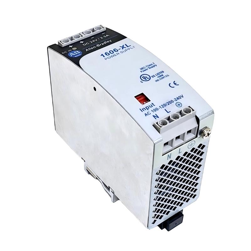
Table of Contents
- Allen Bradley 1606-XL60D Power Supply Overview
- Allen Bradley 1606-XL60D Power Supply Role in a Control System
- Allen Bradley 1606-XL60D Installation Preparation
- Allen Bradley 1606-XL60D Wiring and Protection
- Allen Bradley 1606-XL60D Power Supply Setup
- Allen Bradley 1606-XL60D Commissioning Procedure
- Allen Bradley 1606-XL60D System Configuration and Validation
- Allen Bradley 1606-XL60D Installation Field Case
- Allen Bradley 1606-XL60D Installation FAQ
- Allen Bradley 1606-XL60D Overall Technical Summary
Allen Bradley 1606-XL60D Power Supply Overview
Allen Bradley 1606-XL60D installation should begin with verification of the incoming electrical supply, the required DC output voltage, cabinet conditions, and the load connected to the power supply. In industrial PLC systems, a power supply problem can appear as a controller fault, I/O communication failure, or intermittent module reset even when the PLC hardware itself is healthy. For this reason, the 1606-XL60D Power Supply should be treated as an important part of the complete control-system power architecture.
The 1606-XL60D belongs to the Allen Bradley industrial power supply family and is intended for use in control-panel applications where stable DC power is required for automation equipment. Correct installation is not simply a matter of connecting two wires. An engineer must consider conductor sizing, protective devices, grounding, heat dissipation, load distribution, terminal integrity, and voltage drop.
A practical Installation Guide therefore needs to connect the power supply to the equipment it serves. The final commissioning decision should be based on measured electrical values rather than only on whether the power indicator appears normal.
Allen Bradley 1606-XL60D Power Supply Role in a Control System
In a typical automation cabinet, the power supply provides DC power to devices such as PLC-related equipment, remote I/O, sensors, relays, interface modules, communication equipment, and other control components. The stability of this DC bus directly affects the reliability of the PLC Controller and connected field devices.
When several loads share one power distribution circuit, a disturbance generated by an inductive load can be reflected into the DC control circuit. Solenoid valves, contactors, motor-control interfaces, and relay coils are common examples. Separating sensitive PLC loads from electrically noisy loads can make the entire system easier to commission and troubleshoot.
Allen Bradley 1606-XL60D Power Supply Load Planning
Before energizing the panel, calculate the expected continuous current rather than selecting the power supply only from the nominal current of the largest individual device. Include PLC modules, sensors, communication devices, relay interfaces, and future expansion where appropriate.
- Determine the normal operating current of every connected load.
- Identify loads with high startup or inrush current.
- Separate critical PLC loads from heavy inductive loads where practical.
- Check expected DC voltage drop across long conductors.
- Leave reasonable capacity for engineering expansion.
Allen Bradley 1606-XL60D Installation Preparation
The physical installation location should be selected before wiring begins. A control cabinet should provide adequate ventilation and sufficient space around heat-producing equipment. The power supply should not be installed where another device continuously blows hot air directly onto its enclosure.
Inspect the unit before installation. Look for mechanical damage, loose terminal components, damaged insulation, contamination, or signs of moisture. If a unit has been stored for a long time in an uncontrolled environment, environmental condition should be considered before it is introduced into an energized control cabinet.
Allen Bradley 1606-XL60D Installation Checklist
- Confirm the exact 1606-XL60D model marking.
- Verify the available input power against the application design.
- Confirm the required DC output for the connected control equipment.
- Inspect cabinet ventilation and ambient conditions.
- Prepare correctly sized conductors and protective devices.
- Check that all terminal connections can be accessed safely.
- Confirm that the DC distribution circuit is clearly identified.
Allen Bradley 1606-XL60D Wiring and Protection
Allen Bradley 1606-XL60D wiring should be performed with the cabinet de-energized and isolated according to the site’s electrical safety procedure. The input side and DC output side should be clearly distinguished before conductors are landed.
On the input side, the protective device should be selected according to the electrical design and applicable installation requirements. On the output side, distribution protection should be considered when several branches feed independent PLC or instrumentation loads.
Allen Bradley 1606-XL60D DC Wiring Practice
- Keep power conductors mechanically secure and properly routed.
- Maintain separation between noisy power circuits and sensitive signal wiring.
- Use suitable ferrules or termination methods where required by the panel design.
- Verify conductor polarity before connecting DC loads.
- Ensure terminals are tightened according to the applicable engineering specification.
- Do not rely on wire color alone when identifying polarity.
After wiring, perform a visual inspection before applying power. A reversed DC connection, loose conductor, or misplaced jumper can create a fault immediately after energization and can also damage downstream equipment.
Allen Bradley 1606-XL60D Power Supply Setup
Setup should proceed from the power source toward the load. First verify the input circuit. Then energize the power supply without unnecessary downstream loads when the panel design permits this approach. Measure the output voltage and compare it with the voltage required by the control system.
This approach makes commissioning more diagnostic. If the output is abnormal with no significant load connected, attention should remain on the power supply, input circuit, protection, or wiring. If the output is stable unloaded but collapses after the PLC and field devices are connected, the investigation should move toward load current, short circuits, wiring errors, or excessive inrush.
Input verification:
  AC/DC source = within application design range
  Protective device = correctly rated
  Output polarity = verified

DC output verification:
  VDC(no-load) = measure at power-supply terminals
  VDC(load)   = measure at distribution terminals
  ΔV          = VDC(no-load) - VDC(load)

If ΔV becomes excessive:
  inspect conductor size
  inspect terminal resistance
  check total load current
  isolate downstream branches
Allen Bradley 1606-XL60D Commissioning Procedure
Commissioning is the stage where the installation becomes an operating power circuit. Do not judge the result only by whether the connected PLC Controller starts successfully. A controller may boot correctly while the DC bus is already marginal under load.
Begin with a stable input supply and measure the DC output at the 1606-XL60D terminals. Next measure the same voltage at the PLC or distribution point. A difference between these two measurements indicates a possible distribution problem rather than a power-supply regulation problem.
Allen Bradley 1606-XL60D Commissioning Measurements
- Record the input voltage before applying the normal control load.
- Measure the power-supply DC output with the load disconnected where practical.
- Connect the PLC and essential control loads.
- Measure DC voltage again at the supply terminals.
- Measure voltage at the farthest significant load.
- Observe the supply during relay, contactor, or actuator operation.
- Record abnormal voltage fluctuations for later Fault Diagnosis.
Field commissioning is especially important when the cabinet contains long DC cable runs. A supply can show a healthy terminal voltage while a remote sensor or I/O device receives a substantially lower voltage because of conductor resistance.
Allen Bradley 1606-XL60D System Configuration and Validation
Once the electrical values are stable, validate the complete System Configuration. Start the PLC Controller and confirm that the expected I/O modules, communication devices, sensors, and interface circuits remain online while the process equipment is operating.
Do not immediately connect every non-critical load if the commissioning procedure allows staged energization. Adding branches one at a time gives the engineer a useful current and voltage response for each load group.
Allen Bradley 1606-XL60D Voltage Stability Check
- Check voltage at the supply output.
- Check voltage at the main DC distribution point.
- Check voltage at the most distant important load.
- Observe the DC bus during switching events.
- Confirm that PLC and communication devices do not reset.
- Document measured values in the commissioning record.
Allen Bradley 1606-XL60D Installation Field Case
In one commissioning case involving a PLC control cabinet, the power supply output measured approximately 24.1 VDC during initial unloaded testing. The PLC Controller started normally and communication appeared stable. However, when several remote I/O devices and solenoid interface circuits were energized, the voltage measured at a remote distribution point fell to approximately 22.8 VDC.
The first assumption was that the power supply was undersized. Instead of replacing the unit immediately, the engineer measured the voltage directly at the power-supply terminals while reproducing the event. The supply terminal remained close to its normal operating voltage. The significant voltage loss occurred in the distribution wiring.
The investigation found that several loads had been routed through a relatively long DC conductor path with insufficient consideration of voltage drop. The distribution arrangement was corrected and the sensitive PLC-related loads were separated from the higher-demand branch.
After correction, the remote control voltage remained substantially more stable during switching. The important lesson from this case is that a DC power problem should be diagnosed from the source to the load rather than assuming the power supply itself is defective.
Allen Bradley 1606-XL60D Installation and Commissioning FAQ
What should be checked first during Allen Bradley 1606-XL60D installation?
Verify the exact model, input supply, required DC output, protective arrangement, cabinet environment, wiring polarity, and expected load before energizing the circuit.
Why can a PLC Controller reset even when the 1606-XL60D output appears normal?
The voltage may be normal at the power-supply terminals but unstable at the PLC because of voltage drop, loose terminals, overloaded distribution wiring, or disturbances generated by other loads.
How can Allen Bradley 1606-XL60D Fault Diagnosis be performed efficiently?
Measure voltage at several points rather than relying on a single measurement. Compare unloaded and loaded conditions, then isolate downstream branches to determine whether the abnormal condition follows a specific load.
Should the 1606-XL60D be replaced immediately when the PLC loses power?
No. First determine whether the failure originates at the input, power supply, output terminals, distribution wiring, or downstream load. Replacing a healthy power supply does not correct a wiring or load fault.
What information should be recorded during 1606-XL60D commissioning?
Record input voltage, DC output voltage, load condition, voltage at important distribution points, abnormal switching events, and the operating state of the connected PLC and I/O equipment.
Allen Bradley 1606-XL60D Overall Technical Summary
The Allen Bradley 1606-XL60D Installation Guide should be approached as a complete control-power engineering task rather than a simple terminal-wiring exercise. Correct System Configuration requires appropriate source protection, suitable wiring, proper polarity, controlled load distribution, and measured validation.
For Setup and Commissioning, the most useful field method is to compare electrical conditions at the supply terminals with those at the actual loads. When a PLC Controller or Module behaves intermittently, this measurement-based approach helps distinguish a genuine power-supply problem from voltage drop, wiring resistance, excessive load, or electrical interference.
A properly commissioned 1606-XL60D power circuit provides a more reliable foundation for PLC, I/O, communication, and instrumentation equipment and also makes future Troubleshooting and Fault Diagnosis considerably faster.
“`