

ProductPRODUCT
Featured products



Contact Us
- GE
- DS215UPLAG1BZZ01A
- Power LAN Interface Board
- USA
- 210 × 140 × 50 mm
- 1.29 kg
- Xiamen, China
- New & In Stock
- T/T, PayPal, Western Union
- 1 Year
- 1-3 Working Days
- DHL, UPS, TNT, FedEx and EMS.
- 24-Hour Service
- COO
- 57
Our advantage

Global Logistics
We have a 10-year logistics and express cooperation agreement, so our products can be shipped to any place in the world.

Brand new and original
Our products are imported in bulk from the place of origin. Because of the cooperative relationship, our products are all original and 100% new.

24-hour service
We provide 7*24 hours service to our customers. We will be there whenever you need us.

Price advantage
All our products are priced very favorably because we have our own warehouse and supply.
| Company Information | |||
| [email protected] | |||
| Mobile | +8615980777398 | ||
| +8615980777398 | |||
| 15980777398 |
Product Overview
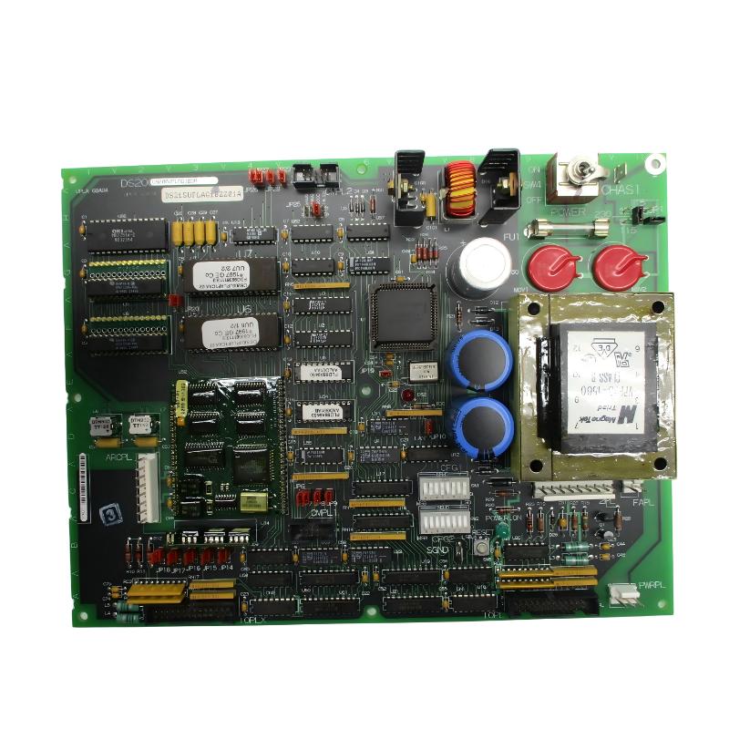
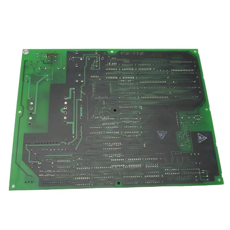
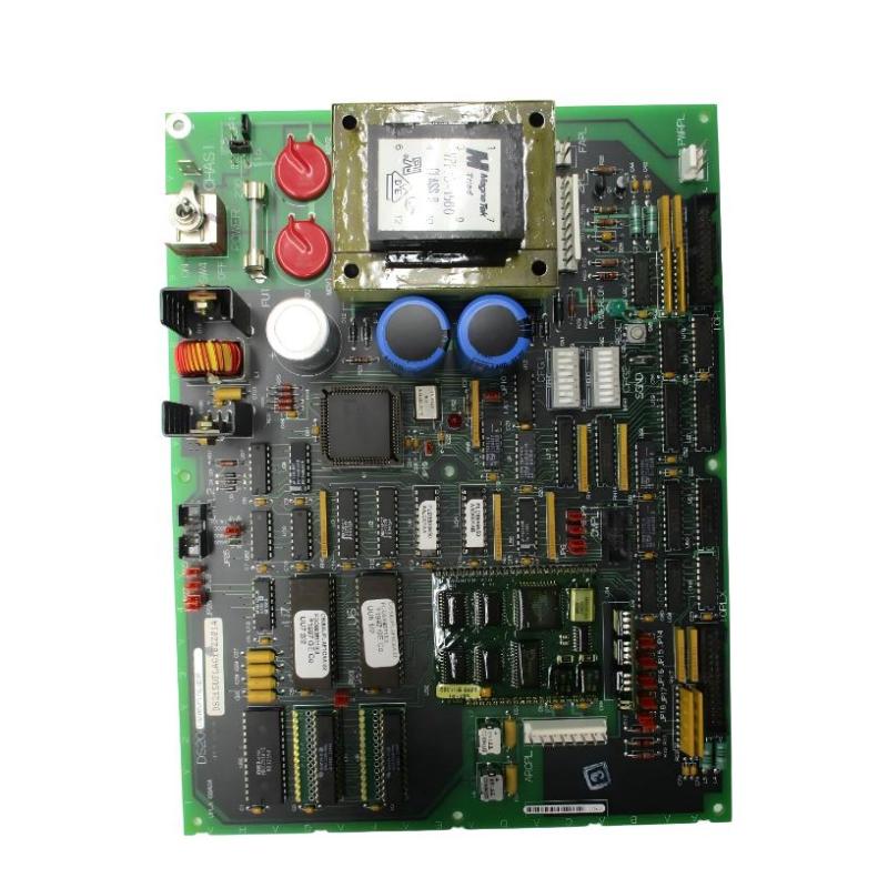
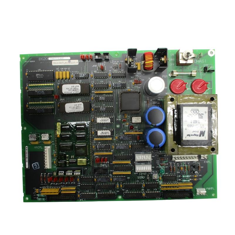
The GE DS215UPLAG1BZZ01A is a Power Supply and LAN Interface Board associated with the GE Mark V turbine control system and GE EX2000 excitation control platform. The board combines power conversion, control processing, firmware execution, and LAN communication functions in a single industrial control assembly.
The UPLAG1 board is designed to provide essential electrical power and communication functions within the control architecture. Unlike a simple power supply module, it incorporates a microprocessor-based control section and communication interfaces, allowing it to participate in both power management and control-system communication.
The DS215UPLAG1BZZ01A is associated with the UPLA functional board family and includes firmware as part of its configured assembly. It is an upgraded version of the earlier DS200UPLAG1A design, with the DS215 assembly incorporating the appropriate firmware configuration.
In a typical installation, the board can receive incoming AC power, convert it into regulated control voltages, and provide the required low-voltage power for associated electronics. At the same time, its LAN interface allows control information to be exchanged with other components in the turbine or excitation control system.
The board therefore serves two important functions within the overall architecture: power conversion and control-system communication.
The specified physical dimensions of the product are 210 × 140 × 50 mm, with a specified weight of 1.29 kg.
Because the DS215UPLAG1BZZ01A contains firmware and configurable hardware, accurate identification is important when replacing the board in a legacy GE control system.
Technical Specifications
| Parameter | Details |
|---|---|
| Manufacturer | GE General Electric |
| Model | DS215UPLAG1BZZ01A |
| Functional Board | UPLAG1 |
| Product Type | Power Supply / LAN Interface Board |
| Functional Acronym | UPLA |
| Series | GE Mark V DS200 |
| Associated Platform | GE EX2000 Excitation Control |
| Firmware | Integrated UPLAG1 firmware configuration |
| Power Input | 115/230 VAC, 50/60 Hz |
| Logic Power | 5 V control logic supply |
| Auxiliary Output | 24 V control power |
| LAN Interface | DLAN+ interface |
| Serial Interface | RS-232C |
| Processor | Microprocessor-based control section |
| Memory | Non-volatile firmware / flash memory capability |
| Configuration | Jumpers and configuration switches |
| Diagnostic Indicators | Power and fault LEDs |
| Reset Function | On-board reset button |
| Protection | On-board fuse and voltage monitoring |
| Dimensions | 210 × 140 × 50 mm |
| Weight | 1.29 kg |
| Application | Turbine control and excitation systems |
| Installation | Industrial control cabinet / VME rack |
What Is the GE DS215UPLAG1BZZ01A?
The GE DS215UPLAG1BZZ01A is a specialized UPLAG1 control assembly that combines a power supply function with LAN communication and firmware-based control processing.
The board belongs to the GE Mark V family and is associated with the EX2000 excitation control environment. Its design allows several important control-system functions to be integrated into one board.
The “DS215” designation identifies the special assembly family, while “UPLAG1” identifies the functional board family. The “B” revision indicates a specific functional hardware revision, while the remaining characters identify the configured assembly and firmware arrangement.
This detailed identification is important because GE produced numerous related Mark V boards with similar physical construction but different electrical and firmware functions.
The DS215UPLAG1BZZ01A should therefore not be treated as a generic power supply board. Its LAN interface, processor, firmware, configuration hardware, and communication capabilities are important parts of its system role.
Function and Working Principle
The DS215UPLAG1BZZ01A performs several functions simultaneously.
At the power-supply level, the board accepts incoming AC power and converts it into regulated DC voltages used by control electronics.
A simplified power path can be represented as:
115/230 VAC Input → Switching Power Supply → Regulated DC Outputs → Control Electronics
The board also contains a microprocessor-based section that executes firmware and manages control-related functions.
At the communication level, the board provides a DLAN+ interface and an RS-232C serial interface for communication with compatible control-system equipment.
The overall operating concept can therefore be represented as:
AC Power → Power Conversion → Control Logic → LAN / Serial Communication → System-Level Control
This combination allows the board to support both the electrical and information-processing requirements of the control system.
Power Supply Function
The power supply section is one of the most important parts of the DS215UPLAG1BZZ01A.
The board is designed to accept either 115 VAC or 230 VAC at 50/60 Hz and convert the incoming power into regulated low-voltage supplies used by associated electronics.
The available control voltages include 24 V and 5 V supplies used by different portions of the control architecture.
The 5 V logic supply is particularly important because the microprocessor and digital logic circuits depend on stable low-voltage power for correct operation.
If the logic supply becomes unstable or falls below its required operating level, the board can initiate a reset condition to protect the processor and prevent unreliable control behavior.
This makes the power supply section directly related to the reliability of the communication and control functions.
LAN Interface Function
The LAN interface is another major feature of the DS215UPLAG1BZZ01A.
The board includes a DLAN+ communication interface that allows it to exchange information with compatible GE control-system components.
Industrial turbine control systems rely on communication between multiple electronic boards. Information may include:
- Control commands
- Status information
- Measurement data
- Diagnostic information
- System configuration data
- Control-state information
- Alarm conditions
The LAN interface allows the UPLAG1 board to participate in this distributed control architecture.
The communication function is especially important in systems where several control boards work together to manage excitation, generator operation, protection, and monitoring.
RS-232C Serial Interface
In addition to the LAN interface, the DS215UPLAG1BZZ01A incorporates an RS-232C serial interface.
Serial communication can be used for service, configuration, diagnostic, or system-interface functions depending on the specific installation.
Because RS-232 communication is point-to-point, it provides a different communication mechanism from the system LAN interface.
During maintenance, the serial interface can be particularly useful when technicians need to communicate with or diagnose a control board without relying exclusively on the main network.
Processor and Firmware
The UPLAG1 board includes a microprocessor core that executes application firmware.
The firmware determines how the processor handles system inputs, communication functions, diagnostic conditions, and control operations.
The board also supports non-volatile memory for retaining firmware and application information.
The general processing sequence can be described as:
Input Data → Microprocessor → Firmware Logic → Control Processing → Communication / Output
This means that the DS215UPLAG1BZZ01A is more than a passive power conversion device. It is an active electronic control component.
Firmware compatibility should therefore be considered when replacing the board.
Configuration Hardware
The board includes multiple configuration resources, including jumpers and configuration switches.
These hardware settings can be used to define board-specific operating conditions depending on the application.
Before removing an existing board, maintenance personnel should record:
- Jumper positions
- Configuration switch positions
- Connector locations
- Cable routing
- Board address settings
- Firmware identification
- Diagnostic LED conditions
These records can simplify replacement and reduce the risk of configuration errors.
Diagnostic Indicators
The DS215UPLAG1BZZ01A provides visual status indication through on-board LEDs.
A green power indicator can show that the board is receiving the required power. A red fault indicator can indicate a board-level error or abnormal operating condition.
When troubleshooting, the LED status should be considered together with the power measurements, communication status, and system alarms.
A useful diagnostic sequence is:
Power LED → Fault LED → Reset → Communication Status → System Diagnostics
The board also includes a reset button that allows the processing section to restart without necessarily removing the entire board from the powered system.
Role in Industrial Control Systems
The DS215UPLAG1BZZ01A operates as part of a larger GE turbine and excitation control architecture.
It can provide power and communication services for the electronic control system while also executing its own firmware-based functions.
A simplified system architecture can be represented as:
Field Measurements → I/O Hardware → Control Processors → UPLAG1 / Communication Network → Excitation System → Generator
Within this architecture, the UPLAG1 board can provide an important bridge between electrical power distribution and control-system communication.
Its role becomes especially important when reliable communication and stable control power are both required for continuous turbine operation.
Industrial Applications
The GE DS215UPLAG1BZZ01A is associated with GE Mark V and EX2000 industrial turbine control systems.
Typical application environments include:
- Gas turbine power plants
- Steam turbine power plants
- Combined-cycle power generation
- Industrial generator systems
- Utility power generation
- Cogeneration plants
- Large excitation control systems
- Industrial turbine automation
- Legacy GE Speedtronic installations
- EX2000 excitation control systems
In these applications, the board can support the electrical power and communication requirements of the control architecture.
Compatible System Components
The DS215UPLAG1BZZ01A is normally integrated with multiple GE control-system components. The exact combination depends on the turbine and excitation-system configuration.
| Component | Type | Typical Function |
|---|---|---|
| DS215UPLAG1BZZ01A | Power Supply / LAN Interface Board | Power conversion and communication |
| DS200UPLAG1A | UPLAG Base Board | Earlier UPLA architecture |
| EX2000 Control Hardware | Excitation Controller | Generator excitation management |
| DS200TCPSG1A | Power Supply Board | Control-system DC power |
| DS200SDCCG1A | Drive Control Board | Main control and processing functions |
| DS200SLCCG1A | LAN / Communication Board | Control-system communication |
| DS200TCQAG1B | Analog I/O Board | Analog signal processing |
| DS200TCRAG1A | Relay Output Board | Discrete relay outputs |
| Terminal Boards | Field Interface | Field signal termination |
| Generator Feedback Devices | Measurement Hardware | Generator and excitation feedback |
| Operator Interface | HMI | Monitoring and control |
These components may work together to create a complete turbine control and excitation system.
Installation and System Integration
Installation of the DS215UPLAG1BZZ01A should be performed by qualified personnel familiar with GE Mark V and EX2000 control systems.
Because the board combines AC power conversion, firmware, processor hardware, and communication interfaces, installation requires careful attention to both electrical and configuration details.
A general replacement procedure includes:
- Place the turbine control system in the approved maintenance state.
- Follow the plant’s lockout and electrical isolation procedures.
- Verify that the relevant AC and DC control power has been isolated.
- Identify the installed UPLAG1 board.
- Record the complete DS215UPLAG1BZZ01A part number.
- Record the board location and rack position.
- Document all cable and connector positions.
- Record jumper settings.
- Record configuration-switch positions.
- Record the status of the power and fault LEDs.
- Verify the replacement board’s firmware configuration.
- Inspect the replacement PCB for physical damage.
- Check all connectors and terminals.
- Install the board in the correct rack position.
- Reconnect the communication and power interfaces.
- Verify connector orientation.
- Check grounding and shielding.
- Restore power according to the approved procedure.
- Check the power-on indication.
- Check the fault indicator.
- Verify LAN communication.
- Verify serial communication if required.
- Confirm control-system operation.
- Complete the required commissioning tests.
The exact installation and commissioning sequence should be adapted to the individual GE control-system configuration.
Power Input Considerations
The power input section should be checked carefully during installation.
The board is associated with 115/230 VAC, 50/60 Hz input power. Incorrect voltage selection or incorrect wiring can damage the board or cause unreliable operation.
Before energizing the board, technicians should verify:
- Correct incoming voltage
- Correct frequency
- Correct wiring
- Correct grounding
- Fuse condition
- Connector seating
- Absence of short circuits
The power supply section should not be tested using procedures that exceed the board’s specified electrical limits.
Maintenance and Troubleshooting
Troubleshooting the DS215UPLAG1BZZ01A should begin with the power supply section before moving to firmware and communication functions.
| Observed Condition | Possible Area to Check |
|---|---|
| Board completely inactive | AC input, fuse, power conversion circuit or connectors |
| Power LED not illuminated | Incoming power, fuse or power-supply section |
| Red fault LED illuminated | Processor, firmware, power or internal board fault |
| Board repeatedly resets | 5 V logic supply, undervoltage condition or processor problem |
| LAN communication lost | DLAN+ cable, connector, network hardware or board interface |
| Serial communication unavailable | RS-232 interface, cable or configuration |
| Intermittent operation | Power quality, connector, cable or component aging |
| Fuse repeatedly blows | Short circuit or downstream component failure |
| Control system reports multiple communication faults | Power, LAN interface or common network problem |
| Incorrect system behavior | Firmware, configuration, communication or associated control hardware |
Power Supply Troubleshooting
If the board does not operate, technicians should first determine whether the correct AC input is available.
The diagnostic path should include:
- Incoming AC voltage
- Input wiring
- Fuse FU1
- Power conversion section
- 5 V logic supply
- 24 V supply
- Processor reset condition
If the fuse is open, it should not simply be replaced repeatedly without identifying the reason for the failure. A repeatedly blown fuse may indicate a short circuit or another failed component on the board or downstream circuitry.
Repeated fuse replacement without fault isolation can create additional damage and should be avoided.
5 V Undervoltage and Reset Conditions
The 5 V logic supply is critical to the processor section.
If the logic voltage falls below the required threshold, the board can initiate a reset condition. This protects the processor from attempting to operate under unstable power conditions.
A repeated reset condition may therefore indicate:
- Unstable incoming power
- Power conversion problems
- Excessive load
- 5 V regulator failure
- Capacitor degradation
- Short circuit
- Board-level component failure
Technicians should measure the power supply according to approved maintenance procedures rather than assuming that the processor itself has failed.
LAN Communication Troubleshooting
When the board has power but cannot communicate with other control components, the LAN interface should be investigated.
Check:
- DLAN+ cable condition
- Connector seating
- Network termination
- Associated control board
- Board configuration
- System communication status
- Power to connected devices
If several boards lose communication at the same time, a common network or power problem is more likely than simultaneous independent board failures.
RS-232 Troubleshooting
If the RS-232C interface is not communicating correctly, technicians should verify the cable, connector, communication settings, and connected equipment.
Possible causes include:
- Incorrect cable connection
- Damaged serial cable
- Incorrect communication configuration
- Faulty serial interface
- Incorrect connected equipment
- Board-level communication failure
Serial communication faults should be separated from LAN communication faults because the two interfaces perform different functions.
Firmware and Configuration Considerations
Because the DS215UPLAG1BZZ01A contains firmware, incorrect firmware configuration can cause problems even when the board is electrically healthy.
During replacement, technicians should compare:
- Complete part number
- UPLAG1 identification
- Functional revision
- Firmware configuration
- Jumper positions
- Configuration switches
- Control-system application
A board with a different firmware package should not automatically be installed simply because the PCB looks similar.
Common Causes of DS215UPLAG1BZZ01A Problems
Potential causes of failure include:
- Incorrect AC input
- Blown fuse
- Power supply component failure
- 5 V undervoltage
- 24 V supply problem
- Damaged LAN cable
- Communication connector failure
- RS-232 interface fault
- Firmware incompatibility
- Incorrect jumper configuration
- Incorrect switch settings
- Processor failure
- Component aging
- Electrical noise
- Grounding problems
- Environmental stress
A systematic diagnostic approach is recommended before replacing the complete board.
Replacement Considerations
When purchasing or preparing a replacement DS215UPLAG1BZZ01A, the complete identification should be checked.
Important information includes:
- DS215UPLAG1BZZ01A
- UPLAG1 functional designation
- UPLA functional acronym
- Functional revision B
- Firmware configuration
- Board location
- Jumper settings
- Configuration-switch settings
- LAN interface requirements
- Associated EX2000 system
The replacement should match the application rather than simply the general description “Power Supply Board.”
Because this assembly combines power and communication functions, an incorrect replacement can affect both electrical power availability and system communication.
Recommended Alternative Models
The following GE models are related power, communication, control, or interface products that may be considered for comparison and spare-parts planning. They should not automatically be treated as direct replacements for the DS215UPLAG1BZZ01A.
| Model | Type | Key Feature | Application |
|---|---|---|---|
| DS215UPLAG1BZZ01A | Power Supply / LAN Interface Board | Power conversion and LAN communication | GE EX2000 / Mark V |
| DS200UPLAG1A | UPLA Board | Earlier UPLAG architecture | GE Mark V / EX2000 |
| DS215UPLAG1AZZ02A | LAN Power Supply Board | UPLA power and communication function | GE turbine control |
| DS200TCPSG1A | Power Supply Board | DC control power distribution | GE Mark V |
| DS200SLCCG1A | LAN / Communication Board | LAN and serial communication | GE Mark V control |
| DS215SLCCG1AZZ01A | Programmer / LAN Interface Board | LAN and programming interface | GE Mark V systems |
| DS200SDCCG1A | Drive Control Board | Main processing and drive control | GE industrial control |
| DS200TCQAG1B | Analog I/O Board | Analog signal processing | GE turbine control |
Replacement recommendation: The preferred replacement is an exact match for DS215UPLAG1BZZ01A, including the UPLAG1 hardware revision and compatible firmware. Related UPLA, LAN, or power-supply boards should only be considered after complete system-level compatibility has been confirmed.
Key Advantages
- Combines power supply and LAN interface functions
- Designed for GE Mark V and EX2000 control environments
- Supports 115/230 VAC input power
- Provides regulated low-voltage control power
- Includes microprocessor-based control processing
- Includes application firmware
- Provides DLAN+ communication capability
- Provides RS-232C serial communication
- Includes diagnostic LED indicators
- Includes an on-board reset function
- Includes hardware configuration resources
- Suitable for legacy turbine control maintenance
Technical FAQs
What is the GE DS215UPLAG1BZZ01A?
The GE DS215UPLAG1BZZ01A is a UPLAG1 Power Supply and LAN Interface Board with firmware, associated with GE Mark V and EX2000 turbine excitation control systems.
What is the main function of the DS215UPLAG1BZZ01A?
Its main functions are to provide regulated control power and support LAN-based communication within the associated GE control architecture.
Is the DS215UPLAG1BZZ01A a power supply board?
Yes, the board includes a power supply section, but it also contains a processor, firmware, communication interfaces, configuration hardware, and diagnostic functions.
Does the board include a LAN interface?
Yes. The UPLAG1 assembly includes a DLAN+ interface used for communication within compatible GE control-system architectures.
Does it have a serial interface?
Yes. The board includes an RS-232C serial interface for compatible service, configuration, or communication functions.
What input power does the board use?
The board is associated with 115/230 VAC input at 50/60 Hz and converts the incoming power into regulated low-voltage control supplies.
What are the specified dimensions?
The specified dimensions are 210 × 140 × 50 mm.
What is the specified weight?
The specified weight is 1.29 kg.
What system is the DS215UPLAG1BZZ01A used in?
It is associated with GE Mark V turbine control and GE EX2000 excitation control systems used in industrial power-generation applications.
What does UPLAG1 mean?
UPLAG1 identifies the functional board family. The DS215 assembly includes the UPLAG1 hardware and its associated firmware configuration.
What causes the power LED to remain off?
Possible causes include missing AC input, an open fuse, a power-supply fault, incorrect wiring, or a board-level power-conversion problem.
What causes repeated board resets?
Repeated resets can be related to unstable 5 V logic power, undervoltage conditions, excessive loading, power-supply faults, processor problems, or other board-level issues.
Can DS200UPLAG1A replace DS215UPLAG1BZZ01A?
The DS200UPLAG1A is an earlier related UPLA board, but it should not automatically be considered a direct replacement. Firmware, hardware revision, communication requirements, and system configuration must be verified first.
Can a standard LAN board replace the UPLAG1 board?
No. The UPLAG1 assembly combines LAN communication with power-supply and firmware-based functions. A standard LAN interface board may not provide the required power or control functions.
How should the DS215UPLAG1BZZ01A be replaced?
The existing board’s complete part number, firmware configuration, jumper settings, switch positions, connector arrangement, and system location should be recorded before replacement. After installation, power, diagnostic indicators, communication, and system operation should be verified.
Conclusion
The GE DS215UPLAG1BZZ01A Power Supply LAN Interface Board is a multifunctional control assembly designed for GE Mark V and EX2000 turbine excitation environments. It combines regulated power conversion, microprocessor-based processing, firmware execution, LAN communication, serial communication, and diagnostic functions in a single industrial board.
Its power-supply function provides the low-voltage electrical resources required by associated control electronics, while the DLAN+ and RS-232C interfaces allow communication with other control-system components. The integrated processor and firmware further distinguish the board from a simple power conversion module.
The specified physical dimensions are 210 × 140 × 50 mm, and the specified weight is 1.29 kg. For maintenance and replacement purposes, the complete identification DS215UPLAG1BZZ01A should be retained.
When troubleshooting this board, technicians should first verify incoming power and fuse condition, then evaluate the 5 V and 24 V control supplies, diagnostic indicators, processor status, LAN communication, serial communication, and firmware configuration. This structured approach can help distinguish a board-level problem from a system-wide power or communication fault.
For engineers, maintenance teams, and spare-parts managers supporting legacy GE turbine automation equipment, the DS215UPLAG1BZZ01A remains an important multifunctional control component. Correct identification of the UPLAG1 hardware and firmware configuration is essential when sourcing a replacement, particularly in systems where reliable control power and communication are both required for continuous turbine and excitation-system operation.