

ProductPRODUCT
Featured products



Contact Us
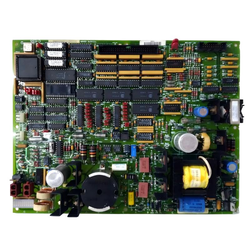
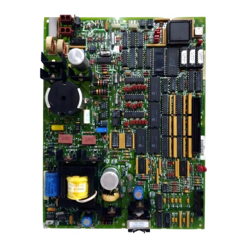
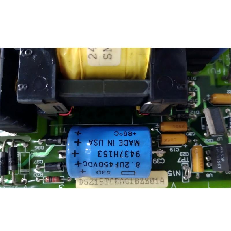
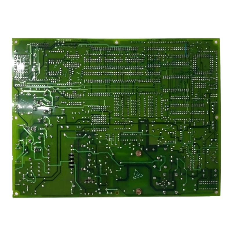
- GE
- DS215TCEAG1BZZ01A DS200TCEAG1BRE
- Emergency Overspeed Baffle
- USA
- 220 × 160 × 25 mm
- 0.65 kg
- Xiamen, China
- New & In Stock
- T/T, PayPal, Western Union
- 1 Year
- 1-3 Working Days
- DHL, UPS, TNT, FedEx and EMS.
- 24-Hour Service
- COO
- 45
Our advantage

Global Logistics
We have a 10-year logistics and express cooperation agreement, so our products can be shipped to any place in the world.

Brand new and original
Our products are imported in bulk from the place of origin. Because of the cooperative relationship, our products are all original and 100% new.

24-hour service
We provide 7*24 hours service to our customers. We will be there whenever you need us.

Price advantage
All our products are priced very favorably because we have our own warehouse and supply.
| Company Information | |||
| [email protected] | |||
| Mobile | +8615980777398 | ||
| +8615980777398 | |||
| 15980777398 |
Product Overview
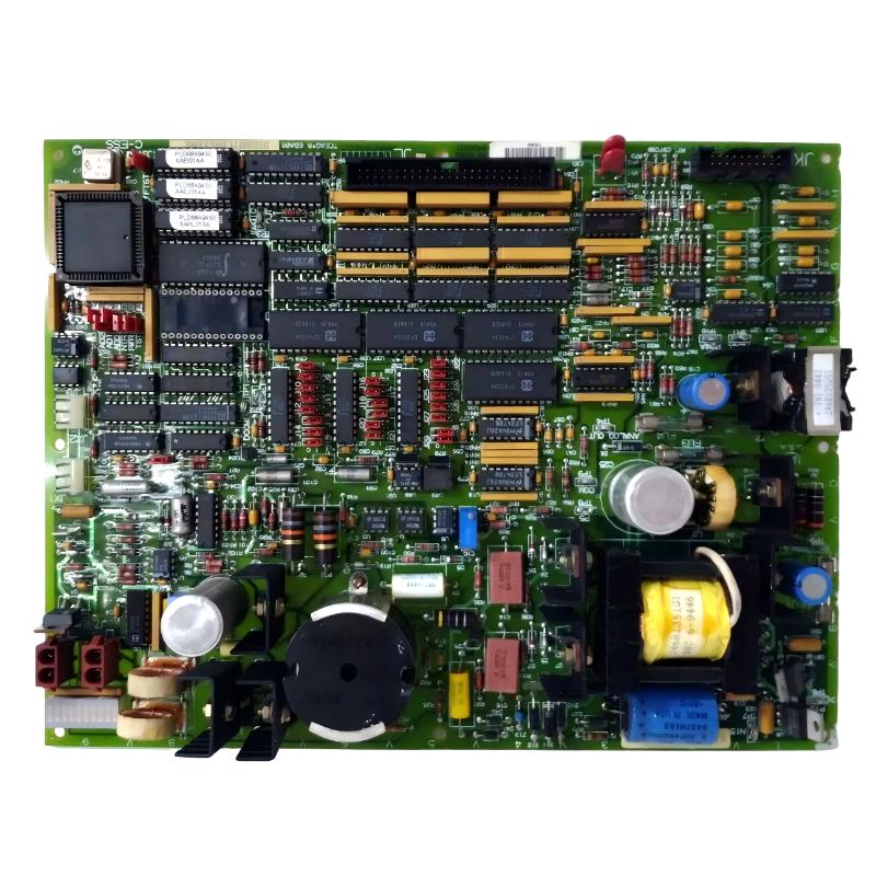
The GE DS215TCEAG1BZZ01A with the associated DS200TCEAG1BRE is an Emergency Overspeed Board designed for compatible GE Mark V Speedtronic turbine control systems. It belongs to the TCEA family of turbine-control hardware and is associated with the processing of critical overspeed and emergency protection signals.
In a turbine control system, speed protection is one of the most important safety functions. Normal turbine control continuously regulates speed and load during operation, but a separate protection function is required to respond when turbine speed exceeds a defined safe operating condition. The emergency overspeed system provides this additional protection layer.
The DS215TCEAG1BZZ01A DS200TCEAG1BRE is therefore not simply a general-purpose control board. It is associated with the emergency overspeed and turbine protection portion of the Mark V architecture. Its function is closely related to monitoring overspeed and flame-detection trip conditions and supporting the appropriate shutdown response.
The DS215 designation identifies the configured board assembly, while DS200TCEAG1BRE identifies the associated DS200-series TCEA board configuration. When replacing this hardware, both identifiers should be considered because the configured assembly and underlying board designation help establish the correct system compatibility.
The specified physical dimensions of this product are 220 × 160 × 25 mm, and the specified weight is 0.65 kg.
Because the board participates in a protection-related function, replacement and commissioning should be performed using the approved procedures for the specific GE Mark V turbine installation. The board should always be treated as part of the complete overspeed protection chain rather than as an isolated circuit board.
Technical Specifications
| Parameter | Details |
|---|---|
| Manufacturer | GE General Electric |
| Model | DS215TCEAG1BZZ01A |
| Associated Board | DS200TCEAG1BRE |
| Functional Family | TCEA |
| Product Type | Emergency Overspeed Board |
| System Family | GE Mark V Speedtronic |
| Primary Function | Emergency overspeed and turbine protection signal processing |
| Protection Function | Overspeed and emergency trip signal processing |
| Additional Protection Input | Flame detection trip-related signals |
| Processing | Microprocessor-based protection processing |
| Memory | Programmable memory devices for board operating instructions |
| Configuration | Hardware jumpers and configurable board resources |
| Protection Interface | Emergency turbine trip architecture |
| Installation | GE Mark V control / protection cabinet |
| Application | Gas turbine and industrial turbine control |
| Dimensions | 220 × 160 × 25 mm |
| Weight | 0.65 kg |
| Service Application | Maintenance, replacement and system restoration |
Function and Working Principle
The primary purpose of the DS215TCEAG1BZZ01A DS200TCEAG1BRE is to provide processing and interface functions associated with emergency overspeed protection in the GE Mark V turbine control system.
A turbine normally operates under closed-loop speed control. Speed sensors provide feedback to the control system, and the controller adjusts the turbine’s energy input to maintain the required operating point.
However, normal control and emergency protection have different objectives. Normal control is intended to optimize turbine operation, while the emergency overspeed function is intended to respond rapidly to a potentially dangerous abnormal condition.
The general protection sequence can be represented as:
Turbine Speed → Speed Detection → Protection Processing → Emergency Trip Decision → Trip Circuit → Energy Shutdown → Turbine Deceleration
The TCEA emergency overspeed board participates in the protection-processing portion of this architecture.
The board is associated with the monitoring and processing of critical trip conditions. These can include turbine overspeed conditions and flame-detection-related trip signals, depending on the system configuration.
Its protection-oriented design allows the Mark V system to distinguish emergency conditions from normal process-control conditions.
Typical signals associated with this protection function may include:
- Turbine speed signals
- Overspeed trip conditions
- Flame detection trip conditions
- Emergency shutdown signals
- Protection status signals
- Trip circuit feedback
- Control-system diagnostic information
When a valid emergency condition is detected, the protection architecture can initiate the appropriate trip response. The final response depends on the turbine design and can involve shutting off fuel, closing steam valves, activating hydraulic trip mechanisms, or performing another approved emergency shutdown action.
Emergency Overspeed Protection
Overspeed protection is designed to prevent turbine speed from increasing beyond the mechanical and operational limits of the turbine.
During normal operation, the primary control system regulates the turbine. If a failure occurs in the normal control loop, however, turbine speed can potentially increase rapidly.
Potential contributing conditions include:
- Speed-control malfunction
- Fuel-control problems
- Steam-valve problems
- Actuator failure
- Sudden load rejection
- Incorrect control-system response
- Faulty speed feedback
- Mechanical abnormalities
- Control configuration problems
The emergency overspeed system provides an additional layer of protection against these conditions.
A simplified operating sequence is:
- Speed sensors detect turbine rotational speed.
- The speed information is transferred into the protection architecture.
- The protection hardware evaluates the speed condition.
- The system determines whether the configured trip condition has been reached.
- An emergency trip command is initiated.
- The turbine energy source is isolated or reduced.
- The turbine begins to decelerate.
- The protection event is investigated before normal operation is restored.
This architecture is important because an emergency protection system should not depend solely on the same control path used for normal turbine regulation.
Overspeed and Flame Detection Functions
The TCEA board is associated with emergency protection signals that can include both overspeed and flame-detection trip conditions.
Flame detection is particularly important in gas turbine applications. A flame-related abnormal condition can require immediate action depending on the operating state and protection configuration.
The board’s association with these signals allows the turbine control system to process protection-related conditions as part of its emergency shutdown architecture.
These functions may interact with:
- Flame detectors
- Speed sensors
- Trip relays
- Emergency shutdown circuits
- Fuel shutoff systems
- Control processors
- Terminal boards
- Protection power supplies
The exact signal configuration depends on the specific turbine and Mark V panel design.
Role in Industrial Control Systems
The GE DS215TCEAG1BZZ01A has a specialized role within the Mark V turbine control architecture.
Industrial turbine control systems generally contain several functional layers. Normal control hardware manages speed, load, temperature, pressure, fuel, and other operating variables. I/O hardware connects field devices to the controller. Protection hardware monitors conditions that may require immediate shutdown.
The TCEA emergency overspeed board belongs to the protection-oriented portion of this architecture.
This separation is important because protection functions must be designed around rapid and dependable response rather than ordinary process-control optimization.
The board may operate together with:
- Mark V control processors
- Speed-monitoring circuits
- Flame detection systems
- Emergency trip circuits
- Trip solenoids
- Fuel control systems
- Steam control systems
- Terminal boards
- Power distribution hardware
- Operator interface systems
These components work together to provide turbine control, monitoring, and protection.
Board Architecture
The DS200TCEAG1BRE is associated with an active electronic board architecture that includes processing and configuration resources.
The board family can include a microprocessor, programmable memory devices, fuses, configurable jumpers, and bayonet-style cable connectors.
The microprocessor provides the processing capability required by the board’s operating functions. Programmable memory devices contain the instructions or configuration information required by the processor.
Hardware jumpers can provide configuration options appropriate to the particular Mark V system.
Fuses provide circuit protection for applicable board power or signal circuits.
Bayonet connectors provide connections to associated system wiring and other control hardware.
Because these components are directly involved in system operation, technicians should inspect them carefully during maintenance.
Industrial Applications
The GE DS215TCEAG1BZZ01A DS200TCEAG1BRE is primarily associated with GE Mark V turbine control and protection systems.
Potential application environments include:
- Gas turbine power generation
- Industrial gas turbine systems
- Combined-cycle power plants
- Power-generation facilities
- Industrial compressor drive turbines
- Process-industry turbine systems
- Petrochemical facilities
- Legacy GE Speedtronic installations
In these applications, emergency overspeed protection helps protect the turbine from abnormal rotational-speed conditions.
The board is particularly relevant in legacy installations where Mark V hardware remains in service and replacement components are required to maintain the existing control architecture.
Compatible System Components
The DS215TCEAG1BZZ01A does not normally operate independently. It forms part of a larger control and protection system.
| Component | Type | Typical Function |
|---|---|---|
| DS200TCEAG1BRE | Emergency Overspeed Board | Associated TCEA protection processing |
| Speed Sensors | Speed Detection Devices | Measure turbine rotational speed |
| Flame Detectors | Protection Sensors | Provide flame status information |
| Mark V Control Processor | Control Hardware | Provides turbine control logic |
| Trip Relay | Protection Interface | Transfers emergency trip commands |
| Trip Solenoid | Actuator | Initiates emergency shutdown action |
| Terminal Boards | Interface Hardware | Provides field signal termination |
| Power Distribution Hardware | Power Interface | Provides system power distribution |
| Fuel Control System | Final Control System | Controls turbine fuel input |
| Steam Control System | Final Control System | Controls steam admission where applicable |
| Operator Interface | HMI | Displays turbine status and alarms |
The actual component combination depends on the turbine model and Mark V control-panel configuration.
Installation and System Integration
Installation of an emergency overspeed board requires careful attention because it participates in a turbine protection function.
Before removing an existing board, technicians should document the complete configuration.
A general installation workflow includes:
- Place the turbine in the approved maintenance state.
- Follow site lockout and isolation procedures.
- Verify that applicable control power has been isolated.
- Confirm that unexpected turbine startup is prevented.
- Record the DS215TCEAG1BZZ01A identification.
- Record the DS200TCEAG1BRE board identification.
- Document the board location.
- Record all cable and connector positions.
- Record jumper positions.
- Document programmable memory device arrangement where applicable.
- Inspect the replacement board for physical damage.
- Check connectors and mounting hardware.
- Install the board in the correct position.
- Reconnect all cables using the correct orientation.
- Verify connector engagement.
- Check grounding and shielding.
- Restore power according to the approved procedure.
- Verify board initialization.
- Check protection-system diagnostics.
- Verify speed and flame-related signal paths.
- Perform approved functional tests.
When disconnecting bayonet-style connectors, the connector body should be handled directly rather than pulling on the cable. This reduces the risk of damaging the cable or separating internal conductors from the connector.
Technicians should also avoid allowing connectors or tools to contact other board components during removal and installation.
Configuration and Jumper Settings
Configuration is an important consideration when replacing a DS200TCEAG1BRE board.
The board family can use hardware jumpers to establish configuration conditions. These settings should be documented before removing the original board.
Recommended pre-removal records include:
- Jumper positions
- Board revision
- Memory device arrangement
- Connector locations
- Cable routing
- Board mounting location
- Associated protection hardware
If a replacement board has different configuration settings, the protection system may not operate as expected.
For this reason, technicians should not assume that factory-default jumper positions are appropriate for every Mark V installation.
Maintenance and Troubleshooting
Troubleshooting the DS215TCEAG1BZZ01A DS200TCEAG1BRE should begin with the complete protection signal chain.
| Observed Condition | Possible Area to Check |
|---|---|
| Overspeed protection alarm | Speed sensors, signal wiring, protection processing and configured thresholds |
| Unexpected turbine trip | Speed signal, flame signal, trip logic, wiring and protection hardware |
| Incorrect speed-related indication | Speed sensor, cable, terminal connection or input circuitry |
| Loss of protection signal | Power, connector, wiring, board or associated sensor |
| Board diagnostic fault | Power supply, processor, memory, jumper configuration or board hardware |
| Intermittent trip signal | Loose connectors, wiring, vibration, electrical interference or board condition |
| Flame detection trip problem | Flame sensor, wiring, input interface or protection logic |
| Protection test failure | Test configuration, signal path, trip interface or board hardware |
A protection alarm does not automatically mean that the TCEA board has failed.
For example, an incorrect overspeed indication can originate from a degraded speed sensor, damaged wiring, a poor connector, electrical interference, or another part of the measurement chain.
Similarly, an unexpected trip can result from a genuine abnormal condition or from an invalid protection input.
Technicians should therefore compare the control-system indication with measured field conditions and available diagnostic information before replacing the board.
Speed Sensor Troubleshooting
Speed measurement is fundamental to overspeed protection.
If the speed signal becomes unstable or incorrect, the protection system may detect a condition that does not correspond to the actual turbine speed.
When investigating abnormal speed-related behavior, technicians should check:
- Speed sensor physical condition
- Sensor mounting
- Sensor wiring
- Connector condition
- Shielding
- Grounding
- Signal stability
- Redundant sensor agreement
- Control-system speed indication
- Protection-system diagnostics
If the measured speed signal is unstable before reaching the TCEA board, replacing the board will not correct the underlying problem.
The troubleshooting process should therefore determine whether the fault is located at the sensor, cable, terminal interface, protection board, or control-system level.
Emergency Trip Circuit
The emergency trip circuit is the final protection path that converts a protection decision into a physical turbine shutdown action.
A simplified protection chain is:
Speed / Flame Detection → TCEA Protection Processing → Trip Interface → Trip Actuator → Energy Isolation → Turbine Shutdown
The exact implementation depends on the turbine design.
The final trip action may involve fuel shutoff, steam-valve closure, hydraulic trip mechanisms, or other emergency control equipment.
During maintenance, the complete trip chain should be considered. A board can be functioning correctly while a downstream relay, solenoid, valve, or wiring circuit is defective.
Common Failure Causes
Potential causes of abnormal emergency overspeed behavior include:
- Degraded speed sensors
- Damaged field wiring
- Loose bayonet connectors
- Incorrect jumper settings
- Memory configuration problems
- Power supply instability
- Board-level component degradation
- Electrical interference
- Grounding problems
- Flame detection signal problems
- Trip relay failure
- Trip solenoid failure
- Incorrect maintenance configuration
These conditions can create similar symptoms, making structured troubleshooting essential.
Replacement Considerations
When selecting a replacement for the GE DS215TCEAG1BZZ01A DS200TCEAG1BRE, the complete identification should be checked rather than relying only on the description “Emergency Overspeed Board.”
Important identification information includes:
- DS215TCEAG1BZZ01A
- DS200TCEAG1BRE
- TCEA functional family
- Hardware revision
- Jumper configuration
- Memory device arrangement
- Connector configuration
- System location
- Associated speed-sensing hardware
- Associated trip-circuit hardware
The exact configured assembly should be matched whenever possible.
Related TCEA boards may look similar but can have different hardware revisions or system-specific configurations. A physically compatible board is not necessarily a functionally compatible replacement.
Because overspeed protection is a critical safety function, replacement verification should be completed before the turbine is returned to normal operation.
Recommended Alternative Models
The following models belong to related GE Mark V control, I/O, or protection hardware families. They may be useful for comparison and spare-parts planning, but they should not automatically be treated as direct substitutes for the DS200TCEAG1BRE.
| Model | Type | Key Feature | Application |
|---|---|---|---|
| DS215TCEAG1BZZ01A | Emergency Overspeed Assembly | Configured TCEA protection assembly | GE Mark V turbine protection |
| DS200TCEAG1BRE | Emergency Overspeed Board | Overspeed and trip signal processing | Mark V turbine control |
| DS200TCEAG1BNE | Emergency Overspeed Board | Related TCEA configuration | Mark V protection systems |
| DS200TCEAG1BSF | TCEA Board | Related emergency control hardware | GE Mark V systems |
| DS200TCEAG1BTF | TCEA Board | Related TCEA configuration | Legacy turbine control |
| DS215TCDAG1BZZ01A | Digital I/O Board | Digital field signal processing | Mark V I/O systems |
| DS200TCDAG1BDB | Digital I/O Board | TCDA digital I/O processing | GE Mark V turbine control |
| DS200TCQAG1B | Control Board | Related control processing | GE Speedtronic systems |
Replacement recommendation: For a replacement project, the closest identification match is the complete DS215TCEAG1BZZ01A DS200TCEAG1BRE assembly. The DS200TCEAG1BNE and other TCEA variants should be evaluated against the original system configuration before being considered for substitution.
Key Advantages
- Designed for compatible GE Mark V Speedtronic turbine systems
- Associated with emergency overspeed protection
- Supports critical turbine protection signal processing
- Associated with overspeed and flame-detection trip functions
- Uses active processing and configurable hardware resources
- Supports emergency turbine trip architecture
- Suitable for legacy GE turbine-control maintenance
- Provides an important interface within the protection chain
- Useful for turbine-control spare-parts planning
- Supports reliable protection operation when correctly configured
Technical FAQs
What is the GE DS215TCEAG1BZZ01A?
The GE DS215TCEAG1BZZ01A is a configured TCEA assembly associated with emergency overspeed protection in compatible GE Mark V Speedtronic turbine control systems.
What is the DS200TCEAG1BRE?
The DS200TCEAG1BRE is the associated DS200-series board identification for the emergency overspeed board configuration described by the DS215TCEAG1BZZ01A assembly.
What is the main function of the DS200TCEAG1BRE?
Its primary role is associated with processing emergency overspeed and related turbine protection signals, including flame-detection trip conditions depending on the system configuration.
What are the dimensions of the DS215TCEAG1BZZ01A?
The specified dimensions are 220 × 160 × 25 mm.
What is the weight of the DS215TCEAG1BZZ01A?
The specified weight is 0.65 kg.
Where is the DS215TCEAG1BZZ01A used?
It is associated with GE Mark V Speedtronic turbine control and protection systems, particularly applications requiring emergency overspeed protection.
What is an emergency overspeed board?
An emergency overspeed board is protection-oriented hardware used to process turbine overspeed-related conditions and support the emergency trip function of the turbine.
Does the board monitor turbine speed?
The TCEA emergency overspeed architecture is associated with processing turbine overspeed protection signals. The actual speed sensing and signal arrangement depends on the specific Mark V turbine configuration.
Does the board also handle flame detection?
The DS200TCEAG1BRE TCEA configuration is associated with overspeed and flame-detection trip conditions. The exact signal allocation depends on the installed turbine control architecture.
What components work with this board?
Typical associated hardware can include speed sensors, flame detectors, terminal boards, Mark V processors, trip relays, trip solenoids, power-distribution hardware, fuel-control equipment, and operator interfaces.
What should be checked before replacing the board?
The complete DS215TCEAG1BZZ01A and DS200TCEAG1BRE identification, board revision, jumper positions, memory arrangement, connectors, wiring, system location, and associated protection hardware should be checked.
Can DS200TCEAG1BNE replace DS200TCEAG1BRE?
They belong to the same general TCEA emergency protection family, but they should not be assumed to be interchangeable without verifying the specific Mark V system configuration, hardware revision, and protection requirements.
What can cause an unexpected overspeed trip?
Possible causes include a genuine abnormal turbine condition, unstable speed feedback, sensor problems, damaged wiring, configuration errors, protection-interface faults, or other problems in the emergency trip chain.
How should this board be tested?
Testing should be performed using the approved diagnostic and commissioning procedures for the specific turbine. Controlled testing should be used rather than intentionally creating an actual turbine overspeed condition.
Conclusion
The GE DS215TCEAG1BZZ01A DS200TCEAG1BRE Emergency Overspeed Board is an important protection-oriented component associated with GE Mark V Speedtronic turbine control systems. It belongs to the TCEA family and is designed for emergency overspeed and related turbine protection signal processing.
Unlike a conventional process-control board, this hardware participates in a protection architecture intended to respond to abnormal turbine conditions. Its associated functions can include processing overspeed and flame-detection trip signals and supporting the emergency trip path that ultimately removes energy from the turbine.
The specified product dimensions are 220 × 160 × 25 mm, and the specified weight is 0.65 kg. The identifiers DS215TCEAG1BZZ01A and DS200TCEAG1BRE should be retained when identifying and sourcing replacement hardware.
For turbine-control engineers and maintenance teams, correct identification is particularly important because emergency protection hardware must match the installed turbine architecture. Jumper configuration, memory devices, board revision, connectors, speed-sensor interfaces, flame-detection signals, and trip circuits should all be verified before commissioning.
When correctly matched with the surrounding Mark V protection and control hardware, the GE DS215TCEAG1BZZ01A DS200TCEAG1BRE provides an important interface within the emergency overspeed protection system. Proper installation, configuration verification, controlled testing, and systematic troubleshooting help maintain the reliability of the overall turbine protection architecture.