

ProductPRODUCT
Featured products



Contact Us
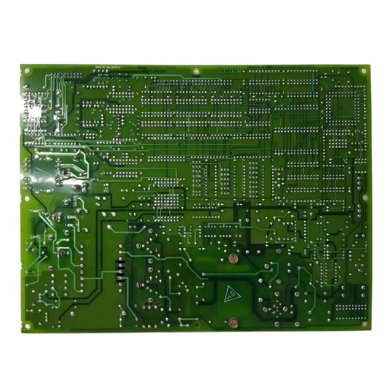
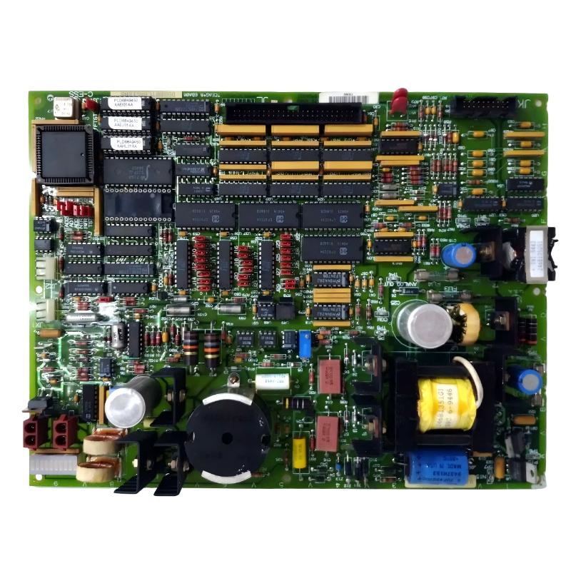
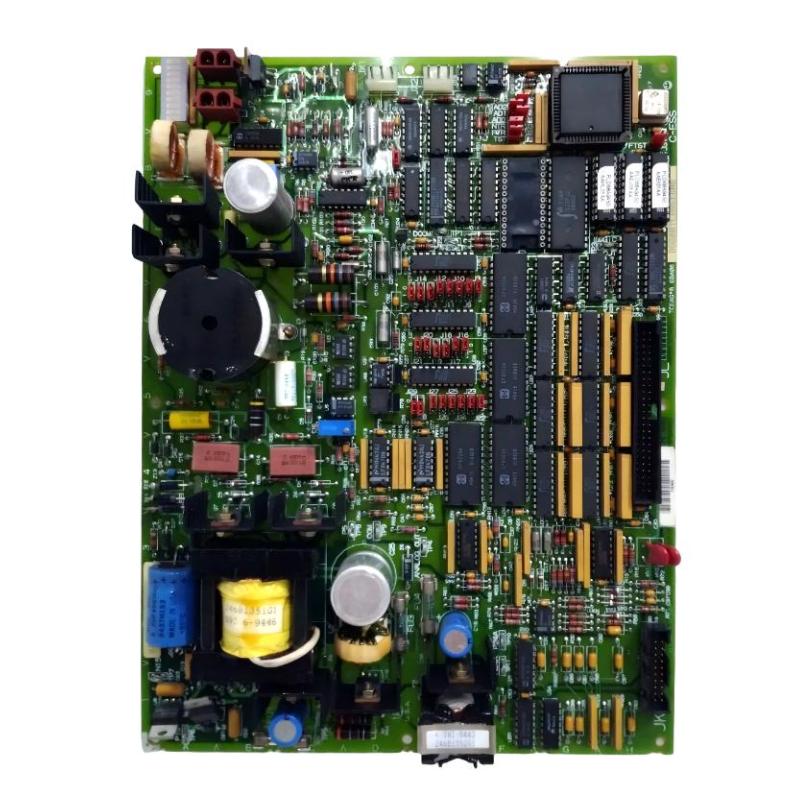
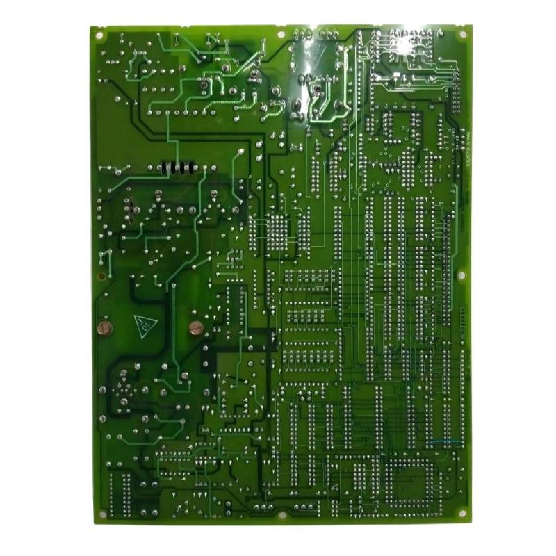
- GE
- DS215TCEAG1BZZ01A DS200TCEAG1BNE
- Emergency Overspeed Baffle
- USA
- 220 × 160 × 25 mm
- 0.65 kg
- Xiamen, China
- New & In Stock
- T/T, PayPal, Western Union
- 1 Year
- 1-3 Working Days
- DHL, UPS, TNT, FedEx and EMS.
- 24-Hour Service
- COO
- 53
Our advantage

Global Logistics
We have a 10-year logistics and express cooperation agreement, so our products can be shipped to any place in the world.

Brand new and original
Our products are imported in bulk from the place of origin. Because of the cooperative relationship, our products are all original and 100% new.

24-hour service
We provide 7*24 hours service to our customers. We will be there whenever you need us.

Price advantage
All our products are priced very favorably because we have our own warehouse and supply.
| Company Information | |||
| [email protected] | |||
| Mobile | +8615980777398 | ||
| +8615980777398 | |||
| 15980777398 |
Product Overview
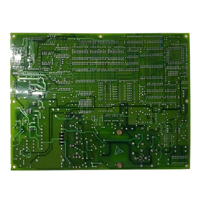
The GE DS215TCEAG1BZZ01A with the associated DS200TCEAG1BNE is an Emergency Overspeed Baffle assembly associated with GE Mark V Speedtronic turbine control systems. This type of hardware forms part of the turbine overspeed protection and control interface architecture, where reliable mechanical and electrical interaction is essential for safe turbine operation.
Turbine speed is one of the most important operating parameters in a power-generation or industrial turbine system. Under normal operating conditions, the control system continuously monitors speed and regulates the turbine to maintain the desired operating point. If turbine speed increases beyond an allowable operating range, the protection system must be capable of responding rapidly and reliably.
The emergency overspeed protection architecture is designed to provide a dedicated layer of protection against abnormal turbine acceleration. The DS215TCEAG1BZZ01A DS200TCEAG1BNE is associated with this protection-oriented portion of the system and is intended for integration with compatible GE turbine-control hardware.
Unlike a conventional general-purpose I/O board, an emergency overspeed-related component should be viewed as part of a protection chain. Its role is associated with the detection, interface, or physical management of conditions related to excessive turbine speed and emergency protection functions.
The specified product dimensions are 220 × 160 × 25 mm, with a specified weight of 0.65 kg.
Because overspeed protection is a safety-critical function, the exact application of a replacement component must always be determined from the turbine’s original control configuration, hardware revision, wiring arrangement, and approved maintenance documentation.
Technical Specifications
| Parameter | Details |
|---|---|
| Manufacturer | GE General Electric |
| Model | DS215TCEAG1BZZ01A |
| Associated Part | DS200TCEAG1BNE |
| Product Type | Emergency Overspeed Baffle |
| System Family | GE Mark V Speedtronic |
| Primary Application | Emergency overspeed protection interface |
| Functional Area | Turbine speed protection |
| Application | Industrial turbine control and protection |
| Installation | Mark V control / protection cabinet or associated assembly |
| System Role | Overspeed protection-related interface |
| Dimensions | 220 × 160 × 25 mm |
| Weight | 0.65 kg |
| Board Family | TCEA |
| Service Application | Maintenance, replacement and restoration of compatible turbine systems |
Function and Working Principle
The DS215TCEAG1BZZ01A DS200TCEAG1BNE is associated with emergency overspeed protection within the GE Mark V turbine control environment.
The basic objective of overspeed protection is straightforward: prevent turbine rotational speed from reaching a condition that could cause mechanical damage or create a hazardous operating situation.
Under normal conditions, turbine speed is controlled through the primary control system. Fuel, steam, or another energy source is regulated to maintain the required turbine speed.
However, a properly designed turbine installation does not rely exclusively on normal control logic. An independent or dedicated protection path is normally used to detect abnormal speed conditions and initiate an emergency response when required.
The simplified protection concept can be represented as:
Turbine Speed → Speed Detection → Overspeed Logic → Emergency Protection Interface → Trip Action → Energy Source Shutdown
The emergency overspeed-related hardware participates in this overall protection chain.
The exact electrical and mechanical function of the baffle assembly depends on the specific Mark V turbine configuration. Therefore, the component should be evaluated as part of the complete protection system rather than as an isolated device.
Overspeed protection can involve several related functions, including:
- Monitoring turbine rotational speed
- Detecting abnormal acceleration
- Comparing speed with protection thresholds
- Initiating emergency trip logic
- Interfacing with trip circuits
- Supporting redundant protection paths
- Preventing continued energy input during a critical overspeed condition
- Providing status information to the control system
The purpose of this architecture is to ensure that abnormal turbine-speed conditions can be handled independently from routine process-control functions.
Role in Industrial Control Systems
The GE DS215TCEAG1BZZ01A belongs to the wider Mark V turbine-control environment, where control and protection functions are distributed across multiple hardware assemblies.
A turbine control system normally performs two fundamentally different tasks. The first is normal operational control, which maintains speed, load, temperature, pressure, and other process parameters. The second is protection, which responds to abnormal conditions that could threaten the turbine, generator, or surrounding equipment.
Overspeed protection belongs to the second category.
The emergency overspeed function is particularly important because turbine rotational energy increases rapidly as operating speed rises. An uncontrolled overspeed event can therefore create significant mechanical stress.
The protection architecture is intended to prevent this condition by initiating an emergency response when the configured protection criteria are reached.
Within a compatible Mark V installation, the TCEA-related hardware may interact with:
- Turbine speed sensors
- Speed monitoring circuitry
- Mark V control processors
- Emergency trip circuits
- Trip solenoids
- Fuel control systems
- Steam admission systems
- Hydraulic trip systems
- Terminal boards
- Power supply assemblies
- Operator monitoring interfaces
The exact combination depends on the turbine model and control configuration.
Emergency Overspeed Protection
Overspeed protection is one of the most important protection functions in a turbine control system.
During normal operation, the primary control system continuously regulates turbine speed. The controller receives speed feedback and adjusts the relevant actuator or energy-control mechanism.
If the primary control function fails or an unexpected condition causes rapid acceleration, a separate protection mechanism must be capable of detecting the abnormal condition.
A typical protection sequence is:
- The turbine accelerates beyond the normal operating condition.
- The speed-monitoring system detects the abnormal condition.
- The measured speed is evaluated against the configured protection threshold.
- The overspeed protection logic determines whether a trip condition exists.
- The emergency trip path is activated.
- The energy source to the turbine is reduced or shut off.
- The turbine begins to decelerate.
- The event is recorded and investigated before restart.
The emergency overspeed baffle is associated with this protection-oriented architecture.
Because the protection system has a different purpose from normal control, technicians should avoid bypassing or modifying protection hardware merely to eliminate a nuisance alarm. Any change to an overspeed protection circuit must follow the approved turbine maintenance and safety procedure.
Why Overspeed Protection Is Important
A turbine is designed to operate within a specific mechanical speed range. Components such as rotors, blades, bearings, couplings, and generators are engineered around defined operating conditions.
An uncontrolled increase in rotational speed can increase mechanical stress and may create serious equipment risks.
Overspeed protection therefore provides an additional layer of defense against failures in the normal control system.
Typical conditions that may contribute to an overspeed event include:
- Primary speed-control failure
- Actuator malfunction
- Valve-control problems
- Fuel-control problems
- Steam-valve malfunction
- Load rejection
- Control-system configuration errors
- Incorrect speed feedback
- Communication or control faults
- Mechanical or process abnormalities
Not every abnormal speed condition originates from the overspeed protection system itself. A structured investigation is therefore required after any protection event.
Industrial Applications
The GE DS215TCEAG1BZZ01A DS200TCEAG1BNE is associated with industrial turbine control and protection applications.
Potential application environments include:
- Gas turbine power generation
- Steam turbine power generation
- Combined-cycle power plants
- Industrial turbine installations
- Cogeneration plants
- Process-industry turbine systems
- Generator drive systems
- Legacy GE Speedtronic installations
In these environments, overspeed protection is integrated with the overall turbine safety architecture.
The component is particularly relevant in systems where continued turbine operation depends on reliable monitoring and emergency shutdown functions.
Compatible System Components
The DS215TCEAG1BZZ01A should be considered as part of a larger turbine control and protection system.
| Component | Type | Typical Function |
|---|---|---|
| DS200TCEAG1BNE | Emergency Overspeed Hardware | Associated TCEA protection function |
| Speed Sensors | Speed Detection Devices | Provide turbine rotational-speed feedback |
| Mark V Control Processor | Control Hardware | Performs turbine control and sequencing |
| Trip Interface | Protection Hardware | Transfers emergency trip commands |
| Trip Solenoid | Actuator | Initiates emergency shutdown action |
| Terminal Boards | Interface Hardware | Provides field wiring termination |
| Power Supply Boards | Power Hardware | Provides required control-system power |
| Fuel Control System | Control Equipment | Controls fuel delivery to turbine |
| Steam Control Valves | Final Control Elements | Controls steam admission |
| Operator Interface | HMI | Displays turbine status and alarms |
The exact system components vary according to the turbine type and Mark V configuration.
Installation and System Integration
Installation of emergency overspeed-related hardware requires more attention than ordinary monitoring equipment because the component participates in a turbine protection function.
Before installation, maintenance personnel should verify the complete part number and compare the replacement component with the original hardware.
A general installation workflow includes:
- Place the turbine in the approved maintenance condition.
- Follow all site isolation and lockout procedures.
- Verify that relevant power sources are isolated.
- Confirm that the turbine cannot start unexpectedly.
- Record the original DS215TCEAG1BZZ01A identification.
- Record the DS200TCEAG1BNE identification.
- Document the original mounting location.
- Record connector and wiring positions.
- Document jumper or configuration settings where applicable.
- Inspect the replacement component for physical damage.
- Check mounting hardware and connectors.
- Install the component in the correct position.
- Reconnect all associated wiring.
- Verify correct connector seating.
- Check grounding and shielding arrangements.
- Restore power using the approved procedure.
- Verify system diagnostics.
- Verify speed-signal integrity.
- Verify protection-system status.
- Perform the approved functional protection checks.
Overspeed protection testing should only be performed using approved commissioning or maintenance procedures. It should never be tested by intentionally creating an uncontrolled turbine overspeed condition.
Where possible, testing should use the designated simulation, diagnostic, or controlled test functions provided for the specific turbine-control architecture.
System Integration Considerations
Correct system integration is essential for emergency overspeed hardware.
The component must be compatible with the installed turbine-control architecture, including its speed-monitoring circuits, trip logic, power supply, terminal interfaces, and emergency shutdown mechanism.
Important integration considerations include:
- Correct board identification
- Correct hardware revision
- Correct connector arrangement
- Correct wiring
- Correct power supply
- Correct speed-signal interface
- Correct trip-circuit configuration
- Correct protection logic
- Correct grounding
- Correct shielding
A mismatch in any of these areas can compromise system operation.
For this reason, the DS215TCEAG1BZZ01A should not be selected solely because the board appears physically similar to another TCEA assembly.
Maintenance and Troubleshooting Considerations
Troubleshooting an emergency overspeed-related component requires a systematic approach.
| Observed Condition | Possible Area to Check |
|---|---|
| Overspeed protection alarm | Speed signal, protection logic, wiring and configured threshold |
| Incorrect speed indication | Speed sensor, wiring, signal interface or processing hardware |
| Unexpected trip | Speed feedback, trip circuit, configuration and protection logic |
| No response to test condition | Test configuration, power, communication, trip circuit or protection hardware |
| Intermittent protection signal | Connectors, wiring, shielding, vibration or hardware condition |
| Board diagnostic fault | Power, configuration, communication or board-level hardware |
| Loss of speed feedback | Sensor, cable, terminal interface or input circuitry |
| Repeated nuisance trip | Speed signal quality, threshold configuration, sensor condition or protection circuit |
It is important to distinguish between a genuine overspeed condition and a false or invalid speed signal.
A speed sensor problem can potentially produce abnormal protection indications without the turbine actually reaching an overspeed condition. Similarly, wiring noise, poor shielding, loose connections, or damaged signal interfaces can create unstable speed information.
For this reason, troubleshooting should examine the complete measurement and protection chain.
Speed Signal Verification
Speed feedback is fundamental to overspeed protection.
Before replacing the protection hardware, technicians should verify the condition of the speed-sensing system.
Relevant checks may include:
- Sensor physical condition
- Sensor mounting
- Sensor-to-target relationship
- Signal wiring
- Connector condition
- Shielding and grounding
- Signal stability
- Redundant sensor agreement
- Control-system speed indication
- Protection-system diagnostic information
If the speed signal is unstable, replacing the TCEA-related hardware may not solve the underlying problem.
Engineers should first determine whether the abnormal signal originates at the sensor, wiring, terminal interface, processing hardware, or protection logic.
Emergency Trip Circuit Considerations
The emergency trip circuit is one of the most critical parts of a turbine protection system.
An overspeed protection event must ultimately result in a controlled reduction of turbine energy input. Depending on the turbine design, this may involve fuel shutoff, steam-valve closure, hydraulic trip action, or another emergency shutdown mechanism.
Because the DS215TCEAG1BZZ01A is associated with the emergency overspeed protection architecture, technicians should evaluate the entire trip chain when diagnosing a protection problem.
The simplified chain can be represented as:
Speed Detection → Protection Logic → Trip Interface → Trip Actuator → Energy Isolation → Turbine Deceleration
A fault anywhere in this chain can affect protection performance.
Maintenance testing should therefore verify not only the electronic board but also the final trip action.
Common Causes of Protection-System Problems
Common causes of abnormal overspeed protection behavior can include:
- Degraded speed sensors
- Damaged signal wiring
- Loose connectors
- Incorrect grounding
- Electrical interference
- Incorrect configuration
- Power-supply instability
- Communication faults
- Board-level component degradation
- Trip-solenoid problems
- Valve or actuator problems
- Incorrect maintenance procedures
These conditions can produce similar symptoms, so the diagnostic process should be based on measured evidence rather than assumptions.
Replacement Considerations
When selecting a replacement for the GE DS215TCEAG1BZZ01A DS200TCEAG1BNE, the complete identification should be verified.
Important information includes:
- DS215TCEAG1BZZ01A
- DS200TCEAG1BNE
- TCEA functional family
- Hardware revision
- Connector arrangement
- System location
- Associated speed-monitoring hardware
- Associated trip-circuit hardware
- Power configuration
A related TCEA board should not automatically be treated as a direct substitute. Protection hardware can have configuration differences that are not obvious from the external appearance.
For a safety-critical application, the replacement should be evaluated against the installed turbine configuration before commissioning.
Recommended Alternative Models
The following models are related to the GE Mark V control and protection architecture and may be considered for comparison or spare-parts planning. They should not be treated as automatic direct replacements without confirming the specific turbine configuration.
| Model | Type | Key Feature | Application |
|---|---|---|---|
| DS215TCEAG1BZZ01A | TCEA Assembly | Configured emergency protection hardware | GE Mark V turbine systems |
| DS200TCEAG1BNE | Emergency Overspeed Hardware | TCEA protection-related assembly | Mark V overspeed protection |
| DS200TCEAG1B | TCEA Board Family | Related interface hardware | GE Mark V control systems |
| DS215TCEAG1BZZ01B | TCEA Assembly | Related configured assembly | Legacy turbine control |
| DS215TCDAG1BZZ01A | Digital I/O Board | Digital field signal processing | GE Mark V I/O |
| DS200TCDAG1BDB | Digital I/O Board | TCDA digital I/O processing | Mark V turbine control |
| DS200TCQAG1B | Control Board | Related turbine control processing | GE Speedtronic systems |
Replacement recommendation: The best starting point is the exact DS215TCEAG1BZZ01A DS200TCEAG1BNE identification. Related TCEA and Mark V boards should only be considered after verifying the complete hardware configuration and protection function.
Key Advantages
- Designed for compatible GE Mark V turbine control environments
- Associated with emergency overspeed protection functions
- Supports turbine protection architecture
- Provides an interface within the emergency protection chain
- Suitable for legacy GE Speedtronic turbine systems
- Supports maintenance and replacement activities
- Can be integrated with speed monitoring and trip hardware
- Designed for industrial turbine control applications
- Useful for turbine-control spare-parts planning
- Supports reliable protection-system architecture when correctly configured
Technical FAQs
What is the GE DS215TCEAG1BZZ01A?
The GE DS215TCEAG1BZZ01A is a configured assembly associated with the TCEA family of GE Mark V turbine control hardware. The associated identification provided for this product is DS200TCEAG1BNE.
What is the DS200TCEAG1BNE?
The DS200TCEAG1BNE is identified with the emergency overspeed protection-related function within the compatible GE Mark V turbine-control architecture.
What is the main purpose of emergency overspeed protection?
Its purpose is to detect or respond to excessive turbine speed and initiate the appropriate emergency protection action before an uncontrolled overspeed condition can cause serious equipment stress or damage.
What are the dimensions of the DS215TCEAG1BZZ01A?
The specified dimensions are 220 × 160 × 25 mm.
What is the weight of the DS215TCEAG1BZZ01A?
The specified weight is 0.65 kg.
Where is this component used?
It is associated with compatible GE Mark V Speedtronic turbine control and protection systems used in power-generation and industrial turbine applications.
Is the DS215TCEAG1BZZ01A a normal digital I/O board?
No. It is associated with the TCEA family and an emergency overspeed protection-related function rather than serving simply as a general-purpose digital I/O board.
What components work with emergency overspeed hardware?
Depending on the turbine configuration, related equipment can include speed sensors, terminal boards, Mark V control processors, trip interfaces, trip solenoids, fuel or steam control systems, power supplies, and operator monitoring equipment.
What should be checked before replacing the DS200TCEAG1BNE?
The complete part number, hardware revision, wiring, connector arrangement, system location, speed-monitoring configuration, trip-circuit configuration, and associated Mark V hardware should be verified.
Can another TCEA board be used as a direct replacement?
Not automatically. TCEA-related assemblies may have different hardware revisions or system configurations. Because overspeed protection is safety-critical, compatibility must be verified against the installed turbine system.
What can cause a false overspeed alarm?
Potential causes include unstable speed-sensor signals, damaged wiring, poor shielding, loose connections, configuration problems, communication faults, or protection-interface problems. A complete diagnostic process is required to identify the actual cause.
How should emergency overspeed protection be tested?
Testing should follow the approved maintenance and commissioning procedure for the specific turbine. Controlled diagnostic or simulation methods should be used where provided. An actual uncontrolled turbine overspeed should never be used as a test method.
Conclusion
The GE DS215TCEAG1BZZ01A DS200TCEAG1BNE Emergency Overspeed Baffle is associated with the emergency overspeed protection architecture of compatible GE Mark V Speedtronic turbine control systems. Its role belongs to the protection side of turbine automation, where reliable detection and response to abnormal turbine-speed conditions are essential.
Unlike ordinary process-control hardware, overspeed protection components form part of a safety-oriented control chain. They work with speed-monitoring equipment, protection logic, trip interfaces, actuators, terminal hardware, and turbine energy-control systems to help prevent dangerous overspeed conditions.
The specified dimensions of this product are 220 × 160 × 25 mm, with a specified weight of 0.65 kg. The complete identifiers DS215TCEAG1BZZ01A and DS200TCEAG1BNE should be retained when identifying replacement hardware.
For maintenance engineers and turbine-control specialists, accurate identification is particularly important because emergency protection hardware must match the installed turbine configuration. Hardware revision, wiring, connectors, speed-sensor interfaces, trip circuits, and associated control components should all be verified before replacement.
When correctly matched with the surrounding Mark V control and protection architecture, the GE DS215TCEAG1BZZ01A DS200TCEAG1BNE can form an important part of the emergency overspeed protection system, supporting reliable turbine operation and providing an additional layer of protection against abnormal rotational-speed conditions.