

ProductPRODUCT
Featured products



Contact Us
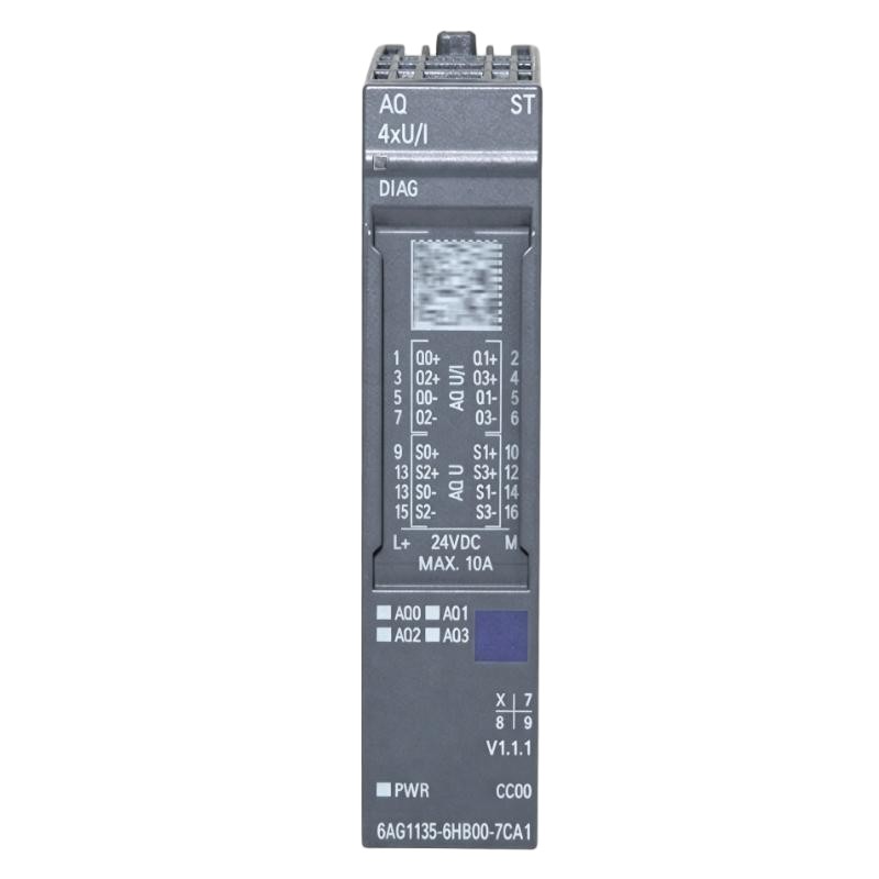
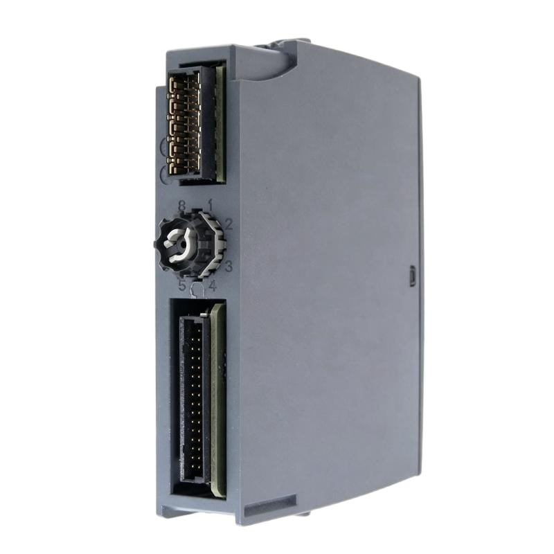
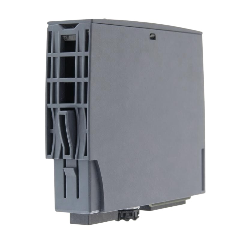
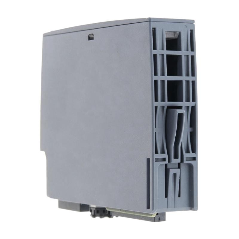
- Siemens
- 6AG1135-6HB00-7CA1
- Analog Output Module
- Germany
- 15 × 73 × 58 mm
- 0.04 kg
- Xiamen, China
- New & In Stock
- T/T, PayPal, Western Union
- 1 Year
- 1-3 Working Days
- DHL, UPS, TNT, FedEx and EMS.
- 24-Hour Service
- COO
- 52
Our advantage

Global Logistics
We have a 10-year logistics and express cooperation agreement, so our products can be shipped to any place in the world.

Brand new and original
Our products are imported in bulk from the place of origin. Because of the cooperative relationship, our products are all original and 100% new.

24-hour service
We provide 7*24 hours service to our customers. We will be there whenever you need us.

Price advantage
All our products are priced very favorably because we have our own warehouse and supply.
| Company Information | |||
| [email protected] | |||
| Mobile | +8615980777398 | ||
| +8615980777398 | |||
| 15980777398 |
Product Overview
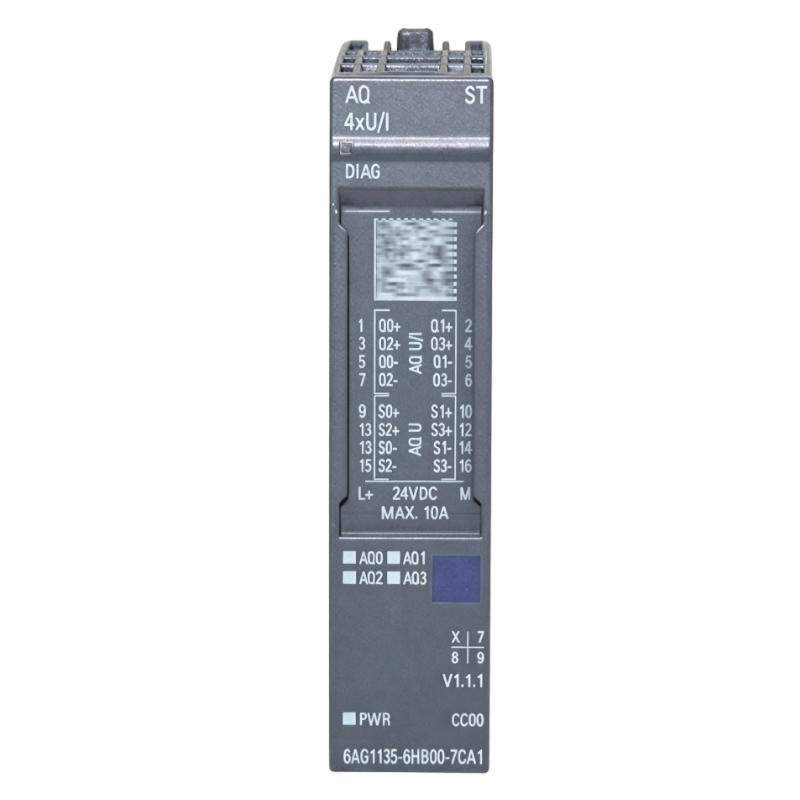
The Siemens 6AG1135-6HB00-7CA1 SIPLUS ET 200S Analog Output Module is an analog output module for Siemens distributed I/O applications. It provides the interface between controller-generated process values and field devices that require variable analog control signals.
In a practical automation system, the PLC handles the control algorithm, interlocks, process calculations, and setpoint generation. The analog output module takes the resulting output data and makes it available to the field side as an analog control signal.
This type of module is commonly associated with proportional control tasks, including actuator references, valve positioning, process regulation, and other industrial equipment where a continuously variable command is required.
The compact ET 200S architecture allows the I/O hardware to be positioned closer to the machine or process. This can simplify field wiring and keep analog signal connections organized around the relevant process equipment.
Technical Specifications
| Parameter | Specification |
|---|---|
| Manufacturer | Siemens |
| Model | 6AG1135-6HB00-7CA1 |
| Product Family | SIPLUS ET 200S |
| Product Type | Analog Output Module |
| Main Function | Analog Signal Output |
| Application | Distributed Analog Control |
| System Architecture | ET 200S Distributed I/O |
| Module Width | 15 mm |
| Dimensions | 15 × 73 × 58 mm |
| Weight | 0.04 kg |
Product Features
The 6AG1135-6HB00-7CA1 is intended for applications requiring analog output capability within a modular Siemens distributed I/O station.
Its practical characteristics include:
- SIPLUS ET 200S analog output module
- Designed for distributed I/O architectures
- Analog field-level output capability
- Suitable for proportional control applications
- Compact 15 mm module format
- Suitable for process and machine automation
- Integrates with Siemens PLC control systems
- Suitable for analog actuator and regulator interfaces
- Supports localized field I/O installation
- SIPLUS construction for demanding industrial environments
- Dimensions of 15 × 73 × 58 mm
- Weight of 0.04 kg
For system engineering, the module should be selected according to the required electrical output characteristics rather than simply by physical dimensions or channel count.
Working Principle
The module acts as the final signal interface between a controller’s digital process value and the connected analog field device.
The basic control path is:
PLC → ET 200S Interface → Analog Output Module → Analog Signal → Field Device
The PLC first calculates the desired output based on the process-control program. This may involve PID control, operator commands, sequence logic, or calculated setpoints.
The output value is transferred through the distributed I/O architecture to the analog output module. The module converts the controller’s value into the corresponding analog electrical signal.
A receiving device such as a valve positioner can then interpret the signal and adjust the physical process accordingly.
For commissioning and troubleshooting, it is useful to distinguish between the software value, physical analog output, and field response. An incorrect actuator position does not necessarily indicate an electronic module failure; scaling, wiring, configuration, and the receiving device can all produce similar symptoms.
Role in a Distributed I/O System
Within an ET 200S installation, the 6AG1135-6HB00-7CA1 provides the analog output point between the distributed control station and the process equipment.
A typical arrangement is:
SIMATIC PLC → Industrial Network → ET 200S Station → 6AG1135-6HB00-7CA1 → Field Device
This architecture is useful when the control cabinet and field equipment are physically separated. The distributed I/O station can be positioned near the machinery, reducing the amount of individual field wiring routed back to the main PLC enclosure.
Potential controlled devices include:
- Proportional control valves
- Analog actuators
- Process regulators
- Speed-reference inputs
- Industrial controllers
- Variable-position devices
- Other compatible analog-input equipment
The module itself does not perform the main control algorithm. Its function is to deliver the controller’s calculated command to the physical process through an analog interface.
Industrial Applications
The module can be incorporated into a variety of industrial automation systems where analog control signals are required.
| Application | Typical Use |
|---|---|
| Process Control | Analog control-loop output |
| Valve Automation | Proportional valve positioning |
| Water Treatment | Distributed actuator commands |
| Chemical Plants | Process regulation |
| Pump Stations | Analog equipment references |
| HVAC Systems | Proportional actuator control |
| Manufacturing Lines | Variable actuator commands |
| Industrial Utilities | Equipment regulation |
| Process Skids | Local analog control |
| Machine Automation | Analog setpoint transmission |
The receiving device must have an input compatible with the configured analog output. Signal scaling should also be coordinated between the PLC program and the field device.
Installation and Maintenance
Installation should be carried out as part of the applicable ET 200S station configuration. The module should not be treated as an independent analog signal converter.
Before installation or replacement, technicians should verify:
- Complete 6AG1135-6HB00-7CA1 order number.
- Existing ET 200S station configuration.
- Interface module compatibility.
- Terminal module arrangement.
- Required system and field power.
- Field device input specifications.
- PLC hardware configuration.
- Channel addressing.
- Analog scaling.
- Signal wiring.
- Shielding and grounding.
- Terminal tightness.
During commissioning, test the output channels individually and compare the PLC command with the actual electrical output. If the measured output is correct but the field device does not respond properly, investigate the cable, terminals, receiving device, and field-side configuration.
For maintenance, inspect analog wiring periodically for loose connections, insulation damage, corrosion, and grounding problems. Analog signals can be more sensitive to installation quality than simple digital switching circuits.
Related Components
The module normally forms part of a larger Siemens distributed I/O arrangement.
| Component | Function |
|---|---|
| SIMATIC PLC | Executes the automation program |
| ET 200S Interface Module | Handles communication between controller and I/O station |
| ET 200S Terminal Module | Provides field wiring connections |
| Power Module | Distributes required electrical power |
| Industrial Communication Network | Transfers process data |
| 24 V DC Power Supply | Provides system and field power |
| Analog Signal Cable | Connects the output to the field device |
| Control Valve Positioner | Converts the analog command into valve movement |
| Analog Actuator | Performs the commanded physical action |
| Control Cabinet | Houses the automation hardware |
The complete signal chain should be considered during system design and troubleshooting. A fault in the field wiring or receiving device can appear as an analog output problem even when the module is operating correctly.
Recommended Related Models
For Siemens analog-output applications, the following models provide useful comparison points based on system architecture and output requirements.
| Model | Product Type | Main Function | Typical Application |
|---|---|---|---|
| Siemens 6AG1135-6HB00-7CA1 | SIPLUS ET 200S Analog Output Module | Analog output | Distributed actuator control |
| Siemens 6AG1135-6HB00-2DA1 | SIPLUS ET 200S Analog Output Module | Analog output | Process and machine control |
| Siemens 6AG1135-6GB00-7BA1 | SIPLUS Analog Output Module | Analog output | Distributed field control |
| Siemens 6AG1135-4GB01-2AB0 | SIPLUS ET 200S Analog Output Module | Current output | Current-based actuator control |
| Siemens 6AG1135-4LB02-7AB0 | SIPLUS ET 200S Analog Output Module | Analog output | Distributed analog applications |
| Siemens 6AG1135-4FB01-2AB0 | SIPLUS ET 200S Analog Output Module | Voltage output | Voltage-controlled devices |
When selecting a replacement, the electrical signal requirements should be checked together with the ET 200S station configuration. A physically similar module from another ET 200 family is not necessarily a direct replacement.
Key Advantages
- Siemens SIPLUS ET 200S analog output module
- Suitable for distributed analog control
- Compact 15 mm module width
- Suitable for proportional actuator applications
- Integrates with Siemens PLC-based architectures
- Supports localized field-level I/O
- Suitable for process and machine automation
- Useful for valve and regulator control
- SIPLUS construction for demanding industrial environments
- Dimensions of 15 × 73 × 58 mm
- Weight of 0.04 kg
Technical FAQs
How does the 6AG1135-6HB00-7CA1 fit into an ET 200S station?
It functions as an electronic analog output module within the distributed I/O station. The interface hardware connects the station to the controller, while the module provides the analog output interface toward the field device.
What is the engineering risk of selecting an analog output module by physical size alone?
Two modules can have identical or similar dimensions while using different signal characteristics, terminal arrangements, or system configurations. The output type, channel configuration, interface system, and PLC hardware configuration should therefore be verified before selecting a replacement.
What should be checked if the analog value changes correctly in the PLC but the actuator remains stationary?
The next step is to measure the physical output from the module. If the electrical signal changes correctly, inspect the field wiring and receiving device. If it does not, check module configuration, scaling, addressing, power, and diagnostic information.
Why is shielding important for analog output wiring?
Analog control signals can be affected by electromagnetic interference, particularly when signal cables run near motors, frequency converters, contactors, or high-current conductors. Proper cable routing, shielding, grounding, and separation from power wiring can reduce unwanted signal fluctuations.