Product Overview
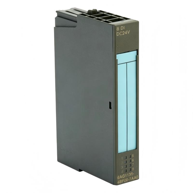
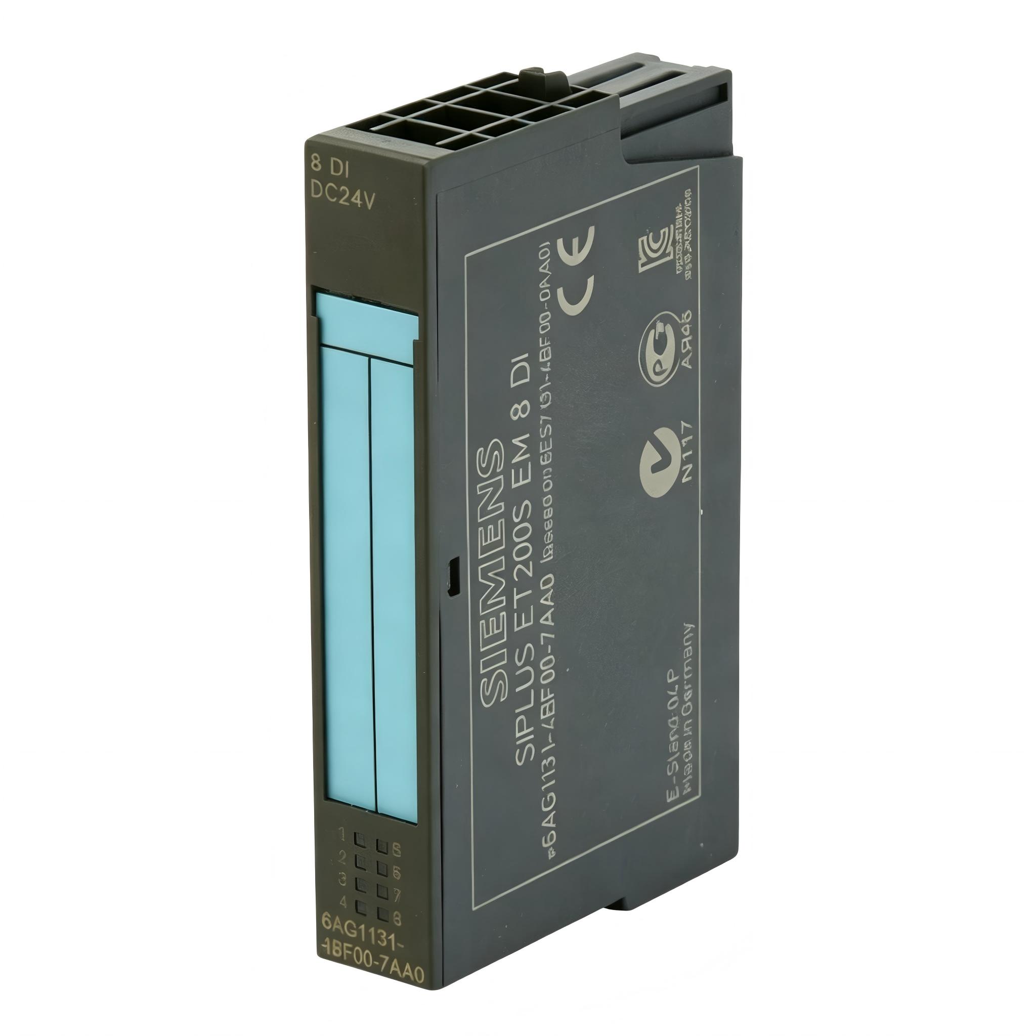
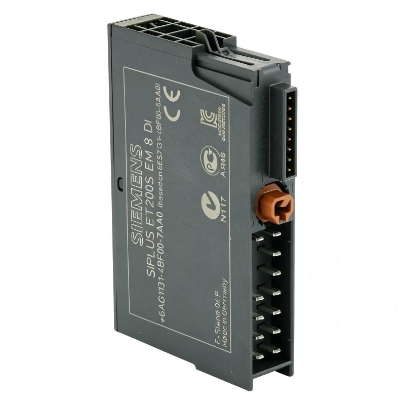
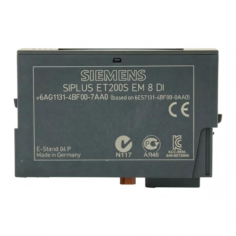
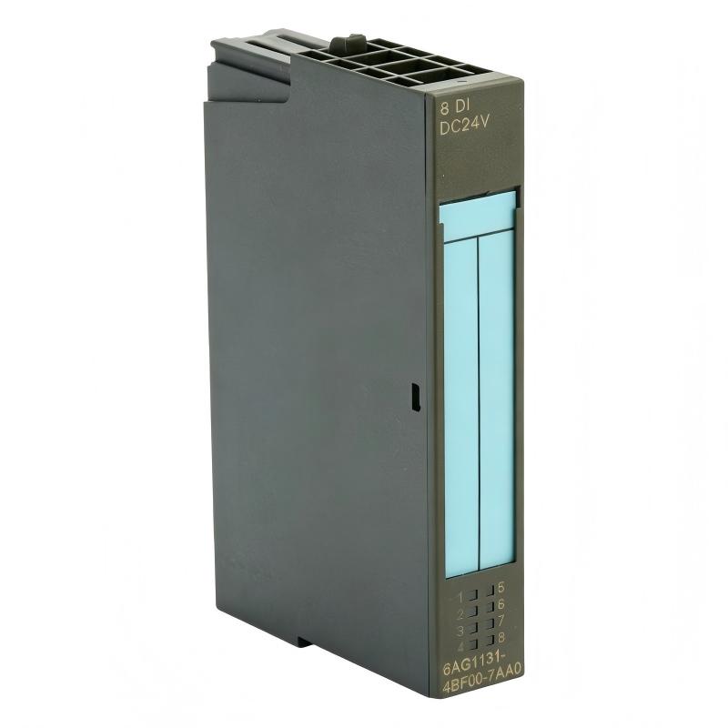
The Siemens 6AG1131-4BF00-7AA0 Digital Input Module is a compact PLC input component designed to acquire discrete field signals and transfer their ON/OFF status to a compatible Siemens automation system. As a digital input interface, the module provides the connection between field devices such as switches, sensors, push buttons, and status contacts and the PLC’s control logic.
The module has a supplied size of 15 × 81 × 52 mm and a weight of only 0.035 kg, making it particularly suitable for compact control cabinets where installation density and low panel weight are important.
A simplified signal path is:
Field Device → Digital Input Module → PLC CPU → Control Logic → Output Module → Actuator
Technical Specifications
| Parameter |
Details |
| Manufacturer |
Siemens |
| Model |
6AG1131-4BF00-7AA0 |
| Product Type |
Digital Input Module |
| Main Function |
Discrete Signal Acquisition |
| Signal Type |
Digital / ON-OFF |
| System Role |
PLC Input Interface |
| Typical Devices |
Switches, Sensors, Push Buttons, Status Contacts |
| Installation |
PLC / Control Cabinet |
| Dimensions |
15 × 81 × 52 mm |
| Weight |
0.035 kg |
Main Functions
The Siemens 6AG1131-4BF00-7AA0 is used to detect the state of connected digital field devices.
Typical applications include monitoring:
- Push buttons
- Selector switches
- Limit switches
- Proximity sensors
- Relay contacts
- Machine status signals
- Safety-related status contacts
- Motor feedback signals
- Valve position signals
- Equipment interlocks
The module converts field-level discrete states into signals that can be processed by the PLC program.
How a Digital Input Module Works
A digital input module essentially determines whether an input circuit is in an active or inactive state.
The basic operating sequence is:
Field Signal
↓
Input Terminal
↓
Input Circuit
↓
Digital Signal Processing
↓
PLC Backplane / System Bus
↓
CPU
↓
PLC Program
For example, when a connected switch changes state, the corresponding input channel detects the electrical condition and communicates the resulting digital status to the PLC CPU.
The PLC program can then use that status to make control decisions.
Role in a PLC Control System
The module acts as the input layer of an automation system.
A typical PLC architecture is:
Sensors / Switches
→
6AG1131-4BF00-7AA0 Digital Input Module
→
PLC CPU
→
Logic Program
→
Digital Output Module
→
Relays / Contactors / Valves / Motors
This architecture allows the PLC to respond automatically to field conditions.
Industrial Applications
The module can be used in compatible Siemens PLC applications such as:
- Factory automation
- Conveyor systems
- Packaging machinery
- Assembly equipment
- Material handling
- Machine tools
- Process automation
- Motor control systems
- Pump stations
- Valve control systems
- Industrial production lines
- Building automation
Installation Guide
Step 1 – Verify the Module
Before installation, confirm:
- Model: 6AG1131-4BF00-7AA0
- PLC system compatibility
- Correct mounting arrangement
- Required field wiring
- Appropriate power and signal architecture
- Correct terminal accessories
Do not install the module into an incompatible PLC system.
Step 2 – Isolate Control Power
Before installation:
- Stop the controlled machine.
- Switch off PLC control power.
- Isolate external field power where required.
- Prevent automatic machine startup.
- Follow appropriate lockout/tagout procedures.
- Verify the circuit is safe.
Digital input wiring can remain energized even when the PLC CPU is stopped, so field power must also be considered.
Step 3 – Inspect the Module
Check the module for:
- Cracks
- Damaged terminals
- Bent connectors
- Contamination
- Corrosion
- Mechanical damage
- Signs of overheating
Do not install a damaged module.
Step 4 – Prepare the Mounting Area
The supplied dimensions are:
15 × 81 × 52 mm
Weight:
0.035 kg
The module is extremely lightweight and compact, but sufficient space should still be provided for:
- Wiring
- Connector access
- Module removal
- Ventilation
- Inspection
Avoid routing high-power cables directly alongside sensitive signal wiring.
Step 5 – Install the Module
Mount the module securely in the appropriate PLC rack or system arrangement.
Check:
- Correct position
- Proper mechanical engagement
- Secure connection
- Correct orientation
- Adequate clearance
Do not force the module into place.
Wiring Guide
Digital Input Wiring
A typical digital input circuit includes:
Field Power → Sensor / Switch → Input Channel → Module Common → Return
Depending on the application, the input may be driven by:
- Mechanical contact
- Electronic sensor
- Proximity device
- Relay contact
- PLC-compatible digital signal
Always follow the electrical requirements of the complete PLC system when wiring the module.
Wiring Inspection
Before applying power, verify:
- Correct terminal assignment
- Correct common connection
- Correct signal polarity
- Secure terminal connections
- Proper cable insulation
- No short circuits
- Correct sensor wiring
A single wiring error can result in a permanently active or inactive input.
Input Signal Testing
After wiring, test each channel individually.
For each input:
- Confirm the field device is inactive.
- Check the corresponding PLC input status.
- Activate the field device.
- Verify the input status changes.
- Return the device to its normal state.
- Confirm the input returns correctly.
This procedure helps identify wiring and channel problems.
PLC Configuration
After physical installation, configure the module within the compatible PLC engineering environment.
Typical configuration tasks may include:
- Hardware identification
- Module placement
- Input addressing
- Channel assignment
- Diagnostic configuration
- Program mapping
- Signal labeling
The exact configuration procedure depends on the Siemens PLC platform and engineering software used by the application.
Commissioning Procedure
Pre-Power Inspection
Before energizing:
- Verify module installation.
- Verify field wiring.
- Check terminal connections.
- Confirm power supply.
- Check common connections.
- Confirm PLC hardware configuration.
Power-Up
After inspection:
- Energize the control system.
- Observe module status.
- Check PLC diagnostics.
- Verify hardware recognition.
- Confirm no configuration errors.
Do not proceed if the PLC reports a module configuration fault.
Channel-by-Channel Testing
Test each connected device.
Verify:
| Test |
Expected Result |
| Field device OFF |
PLC input OFF |
| Field device ON |
PLC input ON |
| Device returned OFF |
PLC input returns OFF |
Each input should respond consistently.
Common Failure Symptoms
| Symptom |
Possible Cause |
| Input always ON |
Short circuit or incorrect wiring |
| Input always OFF |
Missing signal or wiring fault |
| Several inputs inactive |
Common/return connection problem |
| Input status unstable |
Loose wiring or electrical interference |
| Module not recognized |
Installation or configuration issue |
| PLC reports diagnostic fault |
Module or system configuration issue |
| One channel fails |
Channel wiring or input circuit issue |
| Incorrect PLC address |
Hardware configuration problem |
Troubleshooting Guide
Input Always ON
If an input remains active even when the field device is inactive, check:
- Short circuit
- Incorrect terminal connection
- Incorrect common connection
- Sensor output
- Field wiring
- Input configuration
Disconnect the field signal under safe conditions and determine whether the PLC input state changes.
Input Always OFF
Check:
- Sensor power
- Field device operation
- Signal wiring
- Common connection
- Terminal tightness
- Input channel assignment
- PLC configuration
A missing sensor supply can appear to be a failed input module.
Input Status Fluctuates
Possible causes include:
- Loose terminal
- Electrical noise
- Unstable sensor signal
- Poor grounding
- Damaged cable
- Mechanical switch bounce
Inspect both the field device and the wiring before replacing the module.
Module Not Recognized
Check:
- Module seating
- Backplane connection
- Hardware configuration
- PLC compatibility
- Module position
- Controller diagnostics
A configuration mismatch may prevent normal operation even when the module itself is functional.
Multiple Inputs Fail Simultaneously
If several input channels stop working at the same time, investigate the shared circuitry first.
Possible causes include:
- Common connection failure
- Field power loss
- Backplane issue
- Shared wiring fault
- PLC system problem
Multiple simultaneous channel failures are less likely to be caused by independent sensor failures.
Preventive Maintenance
Recommended maintenance includes:
- Inspecting terminals
- Checking field wiring
- Inspecting connectors
- Checking sensor operation
- Reviewing PLC diagnostics
- Checking cabinet contamination
- Inspecting grounding
- Verifying input response
Periodic channel testing can identify developing problems before they cause machine downtime.
System Integration
A digital input module typically works with:
| Component |
Function |
| Sensors |
Generate field signals |
| Switches |
Provide discrete status |
| Digital Input Module |
Acquires ON/OFF signals |
| PLC CPU |
Executes control logic |
| Engineering Software |
Hardware and program configuration |
| Digital Output Module |
Generates control outputs |
| Relays / Contactors |
Interface with equipment |
| Actuators |
Perform physical operations |
The module is therefore an important link between physical equipment and PLC software.
Replacement Procedure
Before Removing the Existing Module
Record:
- Module model
- Module position
- Input addresses
- Terminal assignments
- Sensor wiring
- Common connections
- PLC configuration
Label all field cables before disconnection.
After Installing the Replacement
- Secure the module.
- Verify system connection.
- Reconnect field wiring.
- Check all terminals.
- Restore power.
- Confirm module recognition.
- Check PLC diagnostics.
- Test each input channel.
- Verify the machine sequence.
- Confirm normal operation.
Key Advantages
- Extremely compact design
- Very low weight of 0.035 kg
- Suitable for dense PLC installations
- Provides reliable digital field signal acquisition
- Simplifies integration of switches and sensors
- Supports centralized PLC monitoring
- Dimensions of only 15 × 81 × 52 mm
- Suitable for industrial automation applications
Technical FAQs
What is the Siemens 6AG1131-4BF00-7AA0?
The Siemens 6AG1131-4BF00-7AA0 is a Digital Input Module used to acquire discrete signals from field devices and provide them to a compatible PLC system.
What does a digital input module do?
It detects discrete electrical states, typically representing ON/OFF conditions, and makes those states available to the PLC program.
What devices can be connected?
Depending on the electrical design, typical devices include switches, push buttons, proximity sensors, limit switches, relay contacts, and machine status signals.
What are the supplied dimensions?
The supplied dimensions are 15 × 81 × 52 mm.
What is the weight?
The supplied weight is only 0.035 kg.
Why is an input always ON?
Possible causes include incorrect wiring, a short circuit, incorrect common connections, a continuously active sensor, or a configuration problem.
Why is an input always OFF?
Check the field device, sensor power, signal wiring, common connection, terminal condition, and PLC configuration.
Why do several inputs fail simultaneously?
Check shared power, common wiring, backplane connections, and PLC system conditions before assuming multiple input channels have failed.
Why is an input signal unstable?
Loose wiring, electrical interference, sensor instability, poor grounding, or mechanical contact bounce can cause fluctuating input status.
Should the input module be replaced immediately after a fault?
No. Always check field wiring, sensors, power, common connections, PLC configuration, and diagnostics before replacing the module.
Conclusion
The Siemens 6AG1131-4BF00-7AA0 Digital Input Module provides the interface between discrete field devices and a compatible PLC control system. Its primary purpose is to acquire reliable ON/OFF status information from switches, sensors, contacts, and other field devices so that the PLC CPU can incorporate those signals into its control logic.
With supplied dimensions of 15 × 81 × 52 mm and a weight of just 0.035 kg, the module is particularly well suited to compact and high-density industrial automation installations.
For reliable commissioning, technicians should focus on correct module installation, field wiring, common connections, PLC hardware configuration, input addressing, and channel-by-channel testing. When troubleshooting, use a systematic signal path:
Field Device → Wiring → Digital Input Channel → PLC → Control Logic
This approach makes it easier to distinguish a genuine module problem from sensor, wiring, power, configuration, or PLC-system faults and helps reduce unnecessary replacement and production downtime.