

ProductPRODUCT
Featured products
Contact Us
- Woodward
- 8440-1809
- Control Panel
- USA
- 280 x 200 x 70 mm
- 0.703 kg
- Xiamen, China
- New & In Stock
- T/T, PayPal, Western Union
- 1 Year
- 1-3 Working Days
- DHL, UPS, TNT, FedEx and EMS.
- 24-Hour Service
- COO
- 36
Our advantage

Global Logistics
We have a 10-year logistics and express cooperation agreement, so our products can be shipped to any place in the world.

Brand new and original
Our products are imported in bulk from the place of origin. Because of the cooperative relationship, our products are all original and 100% new.

24-hour service
We provide 7*24 hours service to our customers. We will be there whenever you need us.

Price advantage
All our products are priced very favorably because we have our own warehouse and supply.
| Company Information | |||
| [email protected] | |||
| Mobile | +8615980777398 | ||
| +8615980777398 | |||
| 15980777398 |
Product Overview
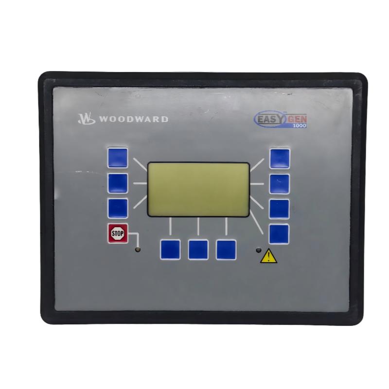
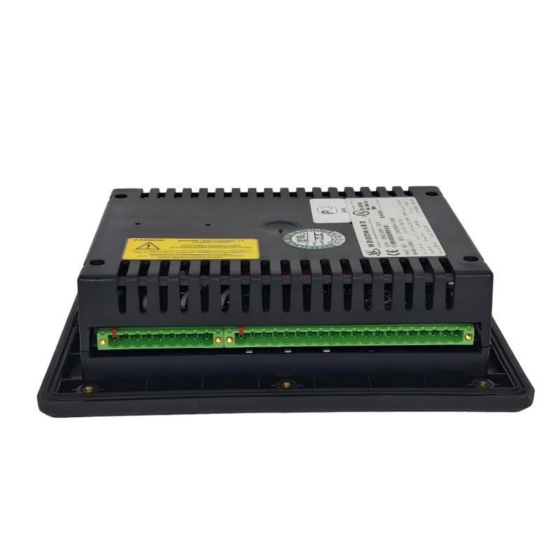
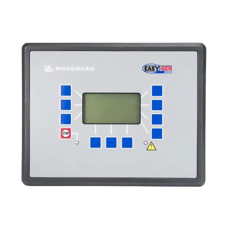
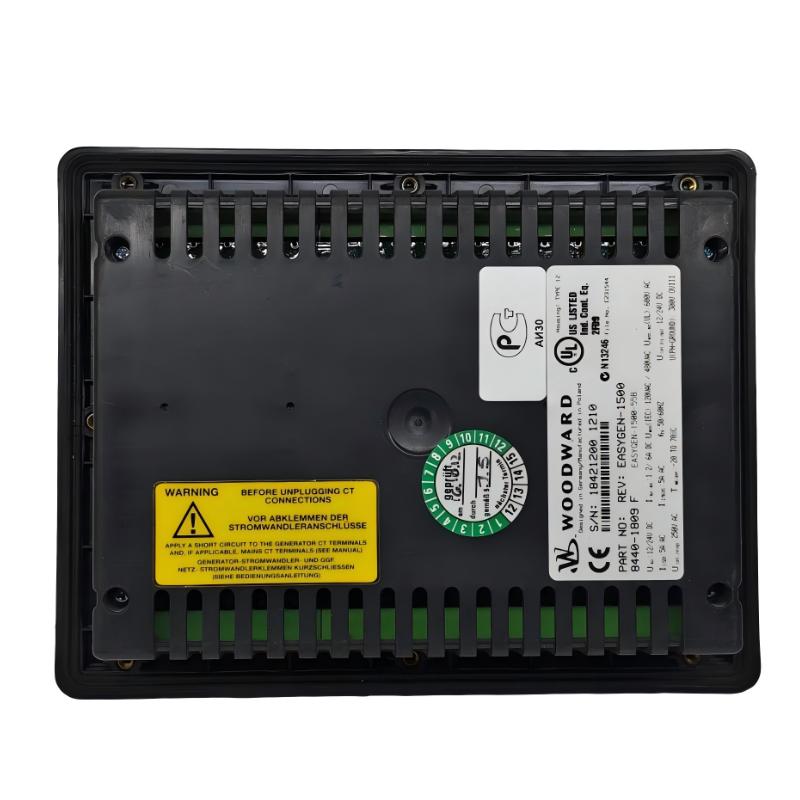
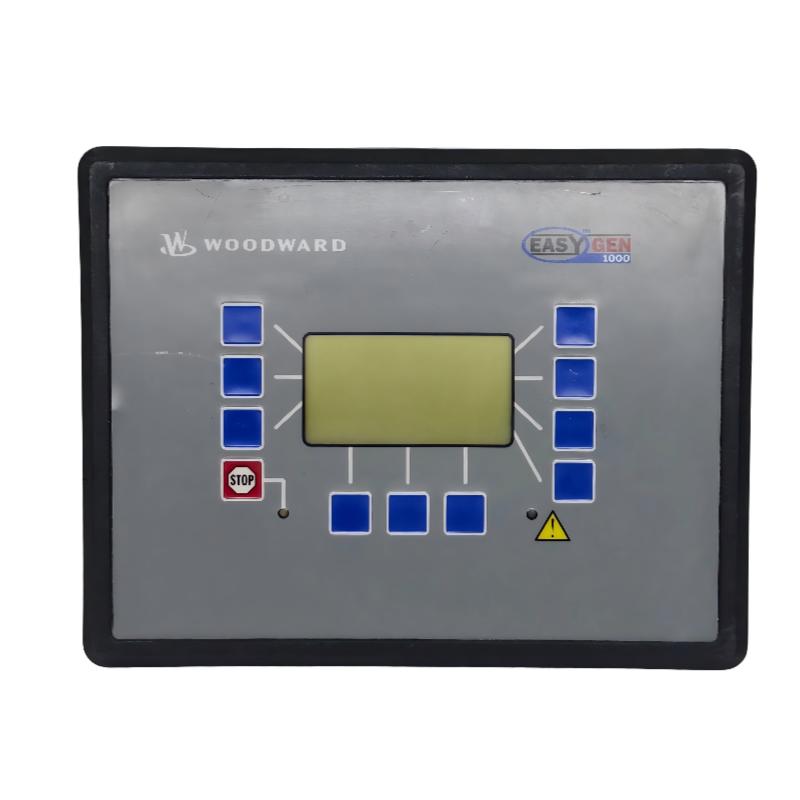
The Woodward 8440-1809 Control Panel is an industrial control interface designed for use in compatible engine, turbine, generator, and industrial automation systems. Acting as the operator’s primary interaction point, the control panel provides access to system monitoring, operational commands, status indication, and control functions while communicating with connected control equipment.
In a typical industrial control architecture, the control panel functions as follows:
Operator Commands → Woodward 8440-1809 Control Panel → Main Controller → Controlled Equipment
With physical dimensions of 280 × 200 × 70 mm and a weight of 0.703 kg, the Woodward 8440-1809 is suitable for installation in industrial control cabinets, generator control consoles, and machine operator panels where reliable human-machine interaction is required.
Technical Specifications
| Parameter | Details |
|---|---|
| Manufacturer | Woodward |
| Model | 8440-1809 |
| Product Type | Control Panel |
| Primary Function | Operator Control and System Monitoring |
| Interface Type | Human Machine Interface (HMI) |
| Typical Application | Generator, Engine and Industrial Control Systems |
| User Functions | Operation, Monitoring and Parameter Adjustment |
| Installation | Control Cabinet / Operator Console |
| Mounting Type | Panel Mount |
| Dimensions | 280 × 200 × 70 mm |
| Weight | 0.703 kg |
Main Functions
The Woodward 8440-1809 Control Panel serves as the communication interface between operators and the automation system.
Typical functions include:
- Equipment status monitoring
- Operator command input
- Alarm indication
- Parameter viewing
- Operating mode selection
- System diagnostics
- Event notification
- Operating data display
- Local equipment control
- Communication with compatible controllers
Actual functionality depends on the connected control system.
Working Principle
The control panel exchanges information between the operator and the main control system.
Typical workflow:
Operator Input
↓
8440-1809 Control Panel
↓
System Controller
↓
Controlled Equipment
↓
Operating Feedback
↓
Display Information
The panel continuously receives operating data from the connected controller and displays equipment status while transmitting authorized operator commands back to the control system.
Role in Industrial Automation Systems
The Woodward 8440-1809 is typically responsible for:
Operator Interaction
Allowing personnel to issue operating commands and monitor system status.
Equipment Monitoring
Displaying operational information received from the control system.
Alarm Notification
Providing visual indication of abnormal operating conditions.
Parameter Management
Supporting viewing and adjustment of configured operating parameters where permitted.
Diagnostic Support
Providing access to controller status and fault information.
Typical Control Architecture
A simplified system architecture may be:
Field Devices
↓
Main Controller
↓
8440-1809 Control Panel
↓
Operator
↓
Control Commands
↓
Main Controller
↓
Equipment Response
The control panel itself generally functions as an interface rather than performing the primary control logic.
Industrial Applications
The Woodward 8440-1809 Control Panel can be used in compatible systems such as:
- Generator control systems
- Engine management systems
- Gas turbine systems
- Steam turbine control
- Power generation plants
- Industrial automation equipment
- Compressor control systems
- Pump control stations
- Marine propulsion systems
- Oil & gas facilities
- Process automation
- Utility power systems
Installation Guide
Step 1 – Verify Equipment
Before installation, verify:
- Woodward 8440-1809
- Complete model number
- Compatible controller
- Communication interface
- Power requirements
- Panel dimensions
- Mounting method
Do not assume compatibility based only on appearance.
Step 2 – Isolate System Power
Before installation:
- Shut down the associated equipment.
- Disconnect control power.
- Disable automatic operation.
- Follow applicable lockout/tagout procedures.
- Verify safe working conditions.
Although the control panel is an interface device, it may issue operational commands to connected equipment.
Step 3 – Document Existing Installation
Before removing an existing panel:
- Photograph wiring
- Label connectors
- Record communication wiring
- Record power wiring
- Save configuration where applicable
- Record network settings
Good documentation simplifies replacement.
Step 4 – Prepare Mounting Location
Supplied dimensions:
280 × 200 × 70 mm
Weight:
0.703 kg
Ensure sufficient space for:
- Cable routing
- Ventilation
- Connector access
- Maintenance
- Panel removal
Avoid excessive vibration, moisture, and direct heat sources.
Step 5 – Inspect the Panel
Before installation inspect for:
- Housing damage
- Display damage
- Loose connectors
- Bent terminals
- Corrosion
- Moisture
- Physical impact damage
Do not install a damaged control panel.
Step 6 – Mount the Control Panel
Install the panel securely.
Verify:
- Proper alignment
- Secure mounting
- Adequate support
- Cable clearance
- Accessibility for operation
The panel should remain stable during normal machine operation.
Step 7 – Connect Power
Before energizing:
Verify:
- Supply voltage
- Wiring polarity
- Ground connection
- Terminal tightness
- Protective devices
Never energize the panel until wiring has been inspected.
Step 8 – Connect Communication
Connect the communication interface according to the system design.
Possible communication connections may include:
- Industrial network
- Serial communication
- Controller interface
- Internal system communication
Verify connector orientation before applying power.
Step 9 – Verify Connected Equipment
Confirm communication with:
- Main controller
- Generator controller
- Engine controller
- Protection devices
- Other connected equipment
The control panel depends on successful communication with the primary controller.
Initial Configuration
Before commissioning, verify:
- Display configuration
- Communication parameters
- System addressing
- Language settings
- User permissions
- Alarm configuration
- Display pages
- Controller connection
Improper configuration may prevent normal operation.
Commissioning Procedure
Pre-Power Inspection
Before applying power:
- Verify mounting
- Verify wiring
- Verify communication
- Check grounding
- Inspect connectors
- Confirm configuration
Power-Up Verification
Apply power and confirm:
- Display startup
- Indicator operation
- Normal initialization
- Communication status
- Alarm indicators
- Controller connection
Any abnormal startup condition should be investigated before proceeding.
Display Verification
Verify that the panel correctly displays:
- Equipment status
- Operating values
- Alarm status
- Communication status
- Controller information
Displayed values should match the connected control system.
Communication Verification
Verify communication between:
- Control panel
- Main controller
- Connected devices
Check for:
- Stable communication
- Correct data updates
- No communication alarms
Functional Test
Verify operator functions such as:
- Menu navigation
- Status viewing
- Command entry
- Alarm acknowledgement
- Parameter access
- Display refresh
Only perform operational commands when safe to do so.
Common Failure Symptoms
| Symptom | Possible Cause |
|---|---|
| Panel does not power on | Power supply problem |
| Blank display | Display or power issue |
| Communication lost | Network or communication fault |
| Incorrect information displayed | Controller communication issue |
| Keys not responding | Hardware or configuration issue |
| Alarm remains active | External system condition |
| Display freezes | Communication or hardware issue |
| Controller unavailable | Communication failure |
| Incorrect parameter display | Configuration issue |
| Intermittent operation | Loose wiring or power instability |
Troubleshooting Guide
Panel Does Not Start
Inspect:
- Incoming power
- Wiring
- Fuse protection
- Grounding
- Connectors
- Power terminals
Verify the external power supply before replacing the panel.
Blank Display
Possible causes include:
- No control power
- Display hardware issue
- Loose connectors
- Incorrect wiring
Confirm power is reaching the unit before further diagnosis.
Communication Failure
Check:
- Communication cable
- Connectors
- Controller power
- Network configuration
- Communication settings
- Network integrity
Communication faults are often external to the panel itself.
Display Information Incorrect
Verify:
- Controller measurements
- Communication integrity
- Configuration
- Display settings
Incorrect displayed values may originate from the controller rather than the panel.
Operator Commands Not Executed
Check:
- Communication
- User permissions
- Controller status
- Interlocks
- Operating mode
- External permissives
The panel may correctly transmit commands that are intentionally blocked by controller logic.
Frozen Display
Inspect:
- Controller communication
- Supply voltage
- Panel restart behavior
- Internal diagnostics
Determine whether the display freeze coincides with communication interruptions.
Preventive Maintenance
Recommended maintenance includes:
- Visual inspection
- Display cleaning
- Connector inspection
- Cable inspection
- Grounding verification
- Communication testing
- Mounting inspection
- Alarm review
- Functional testing
Routine inspection helps maintain reliable operator interface performance.
Environmental Recommendations
Temperature
Install within suitable cabinet temperature conditions.
Moisture
Prevent condensation and direct water exposure.
Dust
Maintain a clean operating environment.
Vibration
Inspect mounting hardware regularly where vibration is present.
Electrical Noise
Route communication cables separately from high-power wiring where possible.
System Integration
The Woodward 8440-1809 typically operates alongside:
| Component | Function |
|---|---|
| Main Controller | Executes control logic |
| 8440-1809 Control Panel | Operator interface |
| Engine Controller | Engine management |
| Generator Controller | Generator control |
| Protection System | Equipment protection |
| Communication Network | Data exchange |
| Operator | System supervision |
| Field Devices | Equipment monitoring |
Control Panel Replacement Procedure
Before removal:
- Save configuration
- Record communication settings
- Photograph installation
- Label cables
- Record connector locations
After installation:
- Verify mounting.
- Verify wiring.
- Apply power.
- Verify display operation.
- Verify communication.
- Confirm controller connection.
- Test display functions.
- Verify alarm indication.
- Confirm stable operation.
Key Advantages
- Compact operator interface
- Reliable industrial panel design
- Supports generator-set supervision
- Compatible with industrial control architectures
- Centralized operating interface
- Supports monitoring and diagnostics
- Dimensions of 280 × 200 × 70 mm
- Lightweight 0.703 kg construction
- Suitable for industrial control cabinets
Technical FAQs
What is the Woodward 8440-1809?
The Woodward 8440-1809 is a Control Panel used as an operator interface for compatible industrial control systems.
What is its primary function?
It provides operator access to system monitoring, alarms, operating information, and control functions.
Does the panel perform control logic?
The primary control logic is typically executed by the connected controller. The panel mainly serves as the human-machine interface.
What are its dimensions?
The supplied dimensions are 280 × 200 × 70 mm.
What is its weight?
The supplied weight is 0.703 kg.
Why is the display blank?
Possible causes include power loss, wiring issues, connector problems, or display hardware faults.
Why are displayed values incorrect?
Incorrect controller data, communication problems, or configuration errors are common causes.
Why are operator commands ignored?
Commands may be blocked by controller logic, operating mode restrictions, communication failures, or system interlocks.
What should be checked before replacing the panel?
Always verify power supply, communication wiring, controller operation, and configuration before assuming panel failure.
What should be verified after installation?
Display operation, communication, controller connectivity, alarms, user interface functions, and stable system operation should all be confirmed.
Conclusion
The Woodward 8440-1809 Control Panel provides an operator interface for compatible industrial generator and automation systems, enabling personnel to monitor operating conditions, view alarms, access diagnostics, and issue authorized control commands.
Reliable installation depends on proper power wiring, communication connections, grounding, mounting, and configuration. Commissioning should verify display functionality, controller communication, operator interaction, and overall system stability before placing equipment into normal service.
For troubleshooting, always examine the complete information path:
Operator → 8440-1809 Control Panel → Main Controller → Controlled Equipment → Feedback
Following this structured approach helps identify whether abnormal behavior originates from the control panel, the communication network, the controller, or connected field equipment, reducing unnecessary component replacement and improving maintenance efficiency.