

ProductPRODUCT
Featured products



Contact Us
- GE
- DS200TBQDG1ACC
- RST Extended Analog Termination Board
- USA
- 215 × 135 × 30 mm
- 0.308 kg
- Xiamen, China
- New & In Stock
- T/T, PayPal, Western Union
- 1 Year
- 1-3 Working Days
- DHL, UPS, TNT, FedEx and EMS.
- 24-Hour Service
- COO
- 44
Our advantage

Global Logistics
We have a 10-year logistics and express cooperation agreement, so our products can be shipped to any place in the world.

Brand new and original
Our products are imported in bulk from the place of origin. Because of the cooperative relationship, our products are all original and 100% new.

24-hour service
We provide 7*24 hours service to our customers. We will be there whenever you need us.

Price advantage
All our products are priced very favorably because we have our own warehouse and supply.
| Company Information | |||
| [email protected] | |||
| Mobile | +8615980777398 | ||
| +8615980777398 | |||
| 15980777398 |
Product Overview
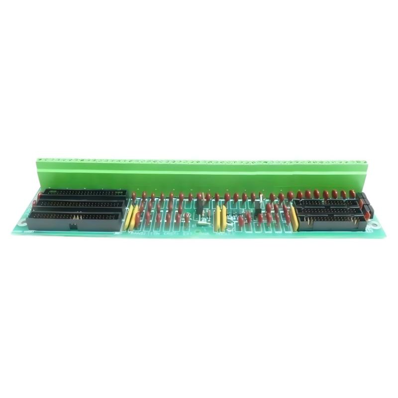
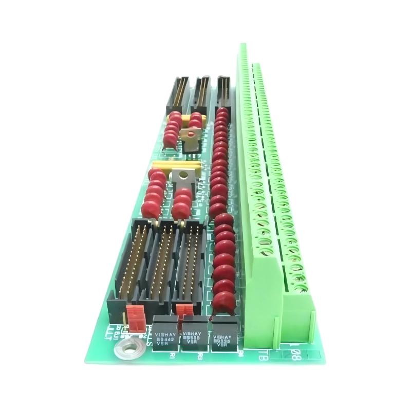
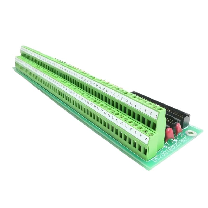
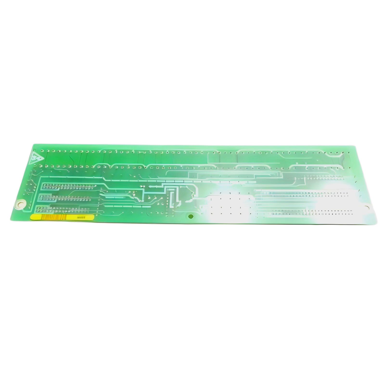
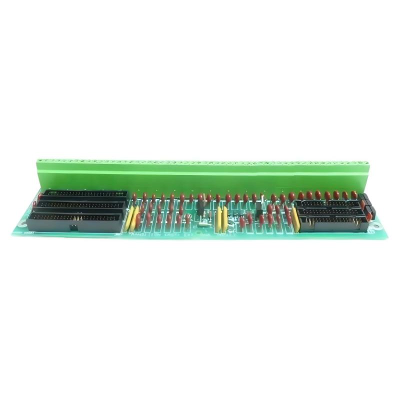
The GE DS200TBQDG1ACC RST Extended Analog Termination Board is a field-interface component associated with compatible GE Mark V control systems. Its primary role is to provide an organized termination and routing point for extended analog instrumentation signals within the RST control architecture.
Terminal boards are positioned between field devices and the control-system I/O electronics. They help organize field wiring, simplify signal identification, and provide a practical interface for maintenance and troubleshooting.
The DS200TBQDG1ACC is identified as an RST Extended Analog Termination Board. For the supplied product specification, the board measures 215 × 135 × 30 mm and weighs 0.308 kg.
Technical Specifications
| Parameter | Details |
|---|---|
| Manufacturer | GE |
| Model | DS200TBQDG1ACC |
| Product Type | RST Extended Analog Termination Board |
| Control Platform | GE Mark V |
| Functional Application | RST Analog Signal Termination |
| Main Function | Extended Analog Signal Termination and Routing |
| Application | Turbine Control / Industrial Automation |
| Interface | Field Instrumentation and Mark V I/O |
| Installation | Industrial Control Cabinet |
| Dimensions | 215 × 135 × 30 mm |
| Weight | 0.308 kg |
Function and Working Principle
The DS200TBQDG1ACC provides an organized electrical interface between field instrumentation and associated Mark V I/O electronics.
A simplified signal path is:
Field Instrument → DS200TBQDG1ACC → Associated I/O Electronics → Mark V Control Processor
The board does not independently perform the complete measurement or control calculation. Instead, it provides the termination and signal-routing infrastructure required for the associated control-system electronics to acquire and process field signals.
Depending on the overall system configuration, extended analog signals may represent:
- Pressure
- Temperature
- Flow
- Level
- Speed
- Position
- Process feedback
- Other continuously varying instrumentation parameters
What Is an Extended Analog Termination Board?
An extended analog termination board is intended to accommodate additional or extended signal-interface requirements within an industrial control architecture.
In a large turbine-control installation, numerous sensors and transmitters can be distributed throughout the equipment. Bringing all field wiring directly to central processing hardware would create unnecessary complexity.
A termination-board architecture instead creates an organized intermediate layer:
Field Devices → Termination Board → I/O Electronics → Controller
This approach can make installation, commissioning, maintenance, and troubleshooting more manageable.
RST Control Architecture
The DS200TBQDG1ACC is identified as an RST Extended Analog Termination Board, meaning its function is associated with the RST portion of the Mark V control architecture.
The RST architecture can be represented conceptually as:
Field Instrumentation
↓
RST Termination Interface
↓
Analog I/O / Signal Conditioning
↓
Mark V Control Processing
↓
Control, Monitoring and Protection
The actual signal path depends on the particular Mark V cabinet and I/O configuration.
Main Features
Extended Analog Signal Interface
The board is designed to provide termination and organization for extended analog field signals.
This can help with:
- Signal identification
- Field-wiring organization
- Channel tracing
- Cabinet maintenance
- Troubleshooting
- System expansion
Industrial Control Application
The board is intended for integration into industrial control environments where continuous process signals must be routed between field instrumentation and control electronics.
Typical applications include turbine and power-generation systems.
Compact Form Factor
The supplied dimensions are:
215 × 135 × 30 mm
The supplied weight is:
0.308 kg
Its relatively compact construction makes it suitable for installation within industrial control cabinets and equipment racks.
Industrial Applications
The DS200TBQDG1ACC can be applied in compatible GE Mark V installations involving:
- Gas turbines
- Steam turbines
- Generator systems
- Power-generation equipment
- Turbine auxiliary systems
- Process monitoring
- Industrial instrumentation
- Rotating machinery
Analog signals are commonly used to monitor continuously changing operating parameters and provide feedback to control logic.
Installation Guide
Step 1 – Verify the Part Number
Before installation:
- Confirm DS200TBQDG1ACC.
- Verify the complete revision suffix.
- Confirm the Mark V cabinet configuration.
- Check the associated I/O architecture.
- Compare the terminal arrangement with the existing board.
- Inspect the replacement board for damage.
Do not assume that similar DS200TBQ-series boards are interchangeable.
Step 2 – Isolate the Control System
Before removing the existing board:
- Shut down the relevant equipment.
- Isolate electrical power.
- Follow site lockout/tagout procedures.
- Verify that the circuits are safe.
- Apply appropriate ESD precautions.
Because turbine-control systems can contain multiple power sources, all applicable circuits should be identified before servicing.
Step 3 – Document Existing Connections
Before disconnecting the original board:
- Record terminal numbers.
- Label field wires.
- Document signal assignments.
- Record connector positions.
- Document jumper settings if present.
- Photograph the original wiring arrangement.
This is especially important when the terminal board handles a large number of analog signals.
Step 4 – Remove the Existing Board
Carefully:
- Disconnect field wiring.
- Disconnect associated connectors.
- Remove mounting hardware.
- Remove the board.
- Place it on an ESD-safe surface.
Avoid pulling on field wires or forcing connectors.
Step 5 – Inspect the Replacement
Before installation, check:
- PCB condition
- Terminal condition
- Connector condition
- Mounting points
- Board revision
- Configuration hardware
If the original board contains configurable components, compare the configuration before installing the replacement.
Step 6 – Install the DS200TBQDG1ACC
Install the board by:
- Aligning the mounting points.
- Securing the board.
- Connecting board-level interfaces.
- Reconnecting field wiring.
- Checking terminal tightness.
- Verifying cable routing.
Every field connection should be checked against the original documentation.
Commissioning Procedure
After installation, commissioning should be performed in stages.
1. Wiring Verification
Check:
- Terminal numbers
- Field-wire identification
- Signal assignments
- Connector seating
- Grounding
- Shielding
2. Signal Verification
Check:
- Signal presence
- Expected signal range
- Channel identification
- Signal stability
- Controller indication
3. Control-System Verification
Confirm:
- Normal diagnostic status
- No unexpected alarms
- Correct process-variable readings
- Stable signal behavior
- Normal control-system response
Common Failure Symptoms
| Symptom | Possible Cause |
|---|---|
| Analog signal missing | Open field circuit |
| Incorrect process value | Wiring or configuration problem |
| Signal fluctuation | Loose connection or electrical interference |
| Intermittent signal | Damaged wiring or connector |
| Multiple inputs fail | Common interface or I/O problem |
| Incorrect channel indication | Wiring misassignment |
| Unexpected alarm | Abnormal input signal |
Troubleshooting Guide
Analog Signal Is Missing
If a channel does not provide a valid value:
- Check the field transmitter.
- Inspect field wiring.
- Verify terminal assignment.
- Check connectors.
- Inspect the termination board.
- Check associated I/O electronics.
- Review Mark V diagnostics.
This sequence helps determine whether the problem originates in the field device, wiring, terminal interface, or control electronics.
Analog Reading Is Incorrect
If a process value appears incorrect:
- Verify the field transmitter.
- Check terminal assignments.
- Inspect wiring continuity.
- Verify signal configuration.
- Check scaling.
- Compare the actual field signal with an independent test instrument.
- Check associated I/O circuitry.
A wrong terminal assignment can produce a perfectly stable but completely incorrect process reading.
Analog Signal Is Unstable
Possible causes include:
- Loose terminal connections
- Damaged field wiring
- Connector problems
- Electrical interference
- Poor shielding
- Grounding problems
- Vibration
- Corrosion
Inspect the entire signal path rather than replacing the board immediately.
Several Analog Signals Fail
When several channels fail simultaneously:
- Inspect common wiring.
- Check shared connectors.
- Verify associated I/O power.
- Inspect related I/O electronics.
- Review system diagnostics.
- Check the termination board.
Multiple simultaneous failures may indicate a common interface problem.
Physical Inspection
During maintenance, inspect the DS200TBQDG1ACC for:
- Burn marks
- Discoloration
- Damaged terminals
- Loose hardware
- Corrosion
- Damaged connectors
- Cracked solder joints
- Contamination
- Mechanical deformation
A detailed visual inspection can often identify mechanical or thermal damage before electrical testing begins.
Preventive Maintenance
Recommended maintenance activities include:
- Periodic terminal inspection
- Field-wiring inspection
- Connector inspection
- Cabinet cleaning
- Corrosion inspection
- Grounding verification
- Signal-trend monitoring
- Review of recurring input alarms
For older Mark V systems, accurate documentation of terminal assignments is particularly valuable for long-term maintenance.
Analog Signal Integrity
Analog signals can be affected by electrical noise and poor installation practices.
For reliable operation:
- Keep analog wiring organized.
- Maintain secure terminal connections.
- Separate sensitive signal cables from high-power wiring where appropriate.
- Maintain proper shielding.
- Verify grounding.
- Protect cables from excessive vibration.
- Keep terminal areas clean.
A damaged or loose connection may appear as signal noise, drift, intermittent operation, or complete loss of an input.
System Integration
The DS200TBQDG1ACC operates as part of a larger control-system signal chain.
| Component | Function |
|---|---|
| Field Sensor | Measures process condition |
| Transmitter | Converts measurement into electrical signal |
| Field Wiring | Carries signal to control cabinet |
| DS200TBQDG1ACC | Terminates and routes extended analog signals |
| I/O Electronics | Conditions and processes signals |
| Mark V Processor | Executes control logic |
| Operator Interface | Displays process information |
| Protection Functions | Respond to abnormal conditions |
Troubleshooting should therefore consider all parts of this chain.
Key Advantages
- Designed for GE Mark V applications
- RST extended analog termination function
- Provides organized field-signal termination
- Supports industrial instrumentation
- Simplifies signal tracing and maintenance
- Suitable for turbine-control environments
- Compact 215 × 135 × 30 mm dimensions
- Lightweight 0.308 kg construction
- Provides an intermediate interface between field wiring and I/O electronics
Technical FAQs
What is the GE DS200TBQDG1ACC?
The GE DS200TBQDG1ACC is an RST Extended Analog Termination Board associated with compatible GE Mark V control systems.
What does the board do?
Its primary function is to provide termination and routing for extended analog field signals before they reach the associated I/O and control electronics.
Is it a processor board?
No. The DS200TBQDG1ACC is a termination/interface board, not the main control processor.
What types of signals can be associated with the board?
Depending on the overall Mark V configuration, analog signals may represent pressure, temperature, flow, level, speed, position, or other continuously varying process parameters.
What are the dimensions?
The supplied dimensions are 215 × 135 × 30 mm.
What is the weight?
The supplied weight is 0.308 kg.
What can cause a missing analog signal?
Possible causes include a failed transmitter, broken field wiring, loose terminal connections, connector problems, incorrect configuration, associated I/O faults, or a termination-board problem.
Should I replace the board if one analog channel fails?
Not immediately. The field device, wiring, terminal connection, configuration, associated I/O electronics, and controller diagnostics should be checked systematically first.
Conclusion
The GE DS200TBQDG1ACC RST Extended Analog Termination Board provides an important field-interface function within compatible GE Mark V control systems. By organizing and routing extended analog signals between field instrumentation and associated I/O electronics, it helps support reliable process measurement and turbine-control operation.
Its role makes accurate wiring, secure terminal connections, correct configuration, and proper signal routing particularly important during installation and maintenance.
With supplied dimensions of 215 × 135 × 30 mm and a weight of 0.308 kg, the DS200TBQDG1ACC offers a compact solution for analog signal termination in industrial control cabinets. A systematic troubleshooting approach—from the field transmitter through the termination interface and I/O electronics to the Mark V controller—is recommended whenever an analog measurement becomes abnormal.