Product Overview
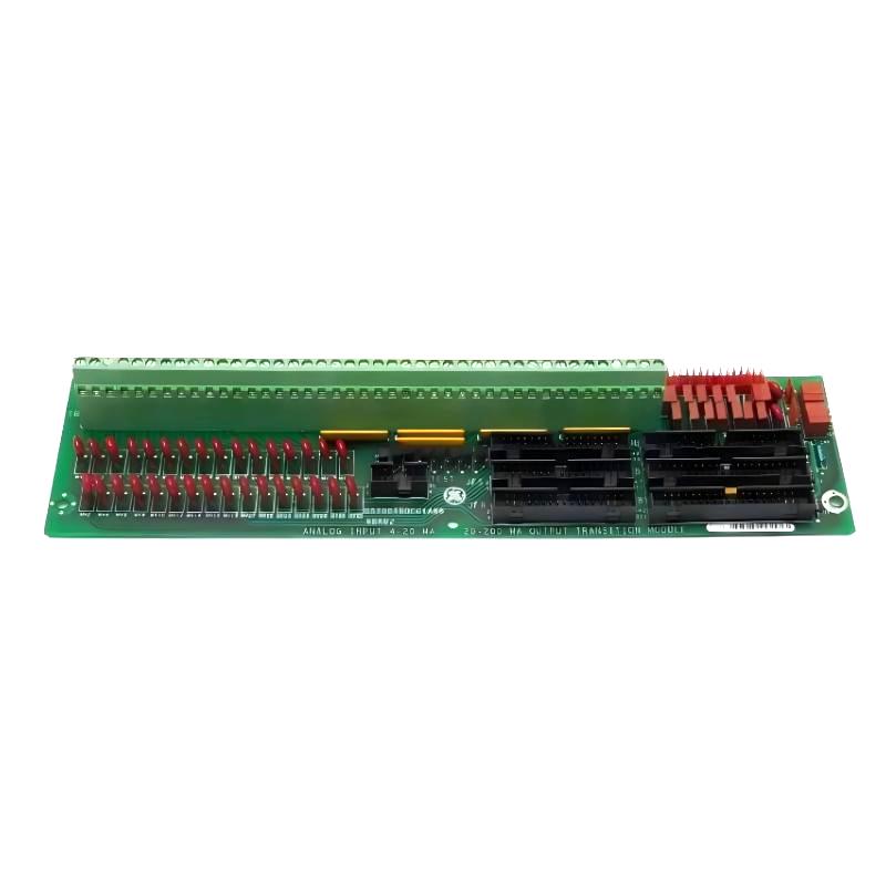
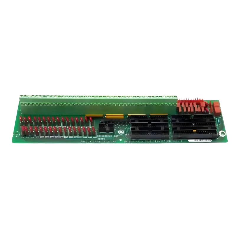
The GE DS200TBQCG1ABB Analog I/O Terminal Board is a field-interface component used in compatible GE Mark V turbine control systems. It provides termination and routing for analog instrumentation signals between field devices and the associated Mark V control electronics.
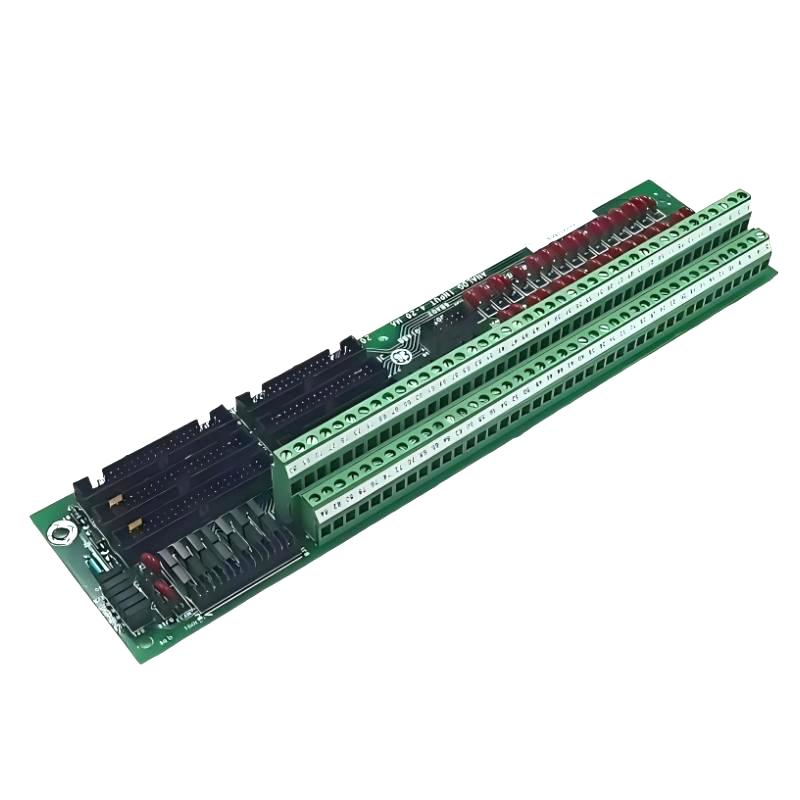
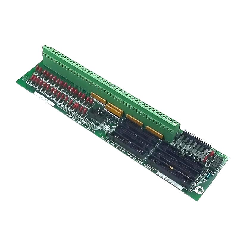
The DS200TBQCG1ABB is specifically associated with the RST analog termination function. Available technical information identifies it as an Analog Input Milliamp I/O Termination Module, with two terminal blocks containing 83 signal terminals each, together with multiple board connectors and configurable jumpers.
The product information supplied for this article specifies dimensions of 260 × 130 × 40 mm and a weight of 0.454 kg. Because revision-specific dimensions and weights can differ between listings, the exact physical characteristics of the installed revision should always be verified before replacement.
Technical Specifications
| Parameter |
Details |
| Manufacturer |
GE |
| Model |
DS200TBQCG1ABB |
| Product Type |
Analog I/O Terminal Board |
| Functional Description |
RST Analog Termination Board |
| Functional Acronym |
TBQC |
| Control Platform |
GE Mark V |
| Main Function |
Analog Input / Milliamp I/O Termination |
| Terminal Blocks |
2 |
| Terminals |
83 per terminal block |
| Configuration |
Multiple board-level connectors and jumpers |
| Application |
Turbine and Industrial Control |
| Dimensions |
260 × 130 × 40 mm |
| Weight |
0.454 kg |
Function and Working Principle
The DS200TBQCG1ABB provides the physical termination interface between field instrumentation and Mark V control electronics.
A simplified signal path is:
Field Transmitter → DS200TBQCG1ABB → Associated I/O Electronics → Mark V Control Processor
The board can be associated with analog milliamp signals used for process measurements and control functions. The actual signal conditioning and processing are performed by the appropriate associated control electronics.
Typical analog instrumentation can represent:
- Pressure
- Flow
- Temperature
- Level
- Speed
- Position
- Process feedback
- Other continuously varying measurements
The terminal board provides the organized connection point that allows these signals to enter and leave the control-system architecture.
Terminal Configuration
The DS200TBQCG1ABB is described as having two terminal blocks, with 83 terminals on each block.
This provides a high-density interface for field signal wiring.
The two terminal blocks can simplify:
- Field-wire organization
- Channel identification
- Signal tracing
- Maintenance
- Troubleshooting
- Cabinet wiring management
Because terminal numbering is system-specific, technicians should use the applicable wiring documentation rather than relying on assumptions based on physical location.
Connectors and Interface Hardware
The DS200TBQCG1ABB is also described as having:
- 3 × 40-pin connectors
- 3 × 34-pin connectors
- Multiple configuration jumpers
Identified connector functions include interfaces associated with TCQA boards, LVDT/R position input signals, and test or auxiliary connections.
The board also includes jumper-configurable circuitry. Therefore, when replacing an existing board, jumper positions should be documented before removal and reproduced on the replacement where applicable.
Mark V System Integration
The DS200TBQCG1ABB is part of the GE Mark V control architecture used in industrial turbine applications.
A simplified architecture is:
Field Sensors / Transmitters
↓
Analog Termination Board
↓
I/O and Signal-Conditioning Electronics
↓
Mark V Processor
↓
Control / Monitoring / Protection Functions
The terminal board therefore forms part of the signal-interface layer rather than acting as the primary control processor.
Industrial Applications
The DS200TBQCG1ABB is suitable for compatible Mark V control installations involving:
- Gas turbines
- Steam turbines
- Power-generation equipment
- Turbine auxiliary systems
- Generator monitoring
- Industrial process control
- Rotating machinery
- Industrial instrumentation
Main Features
High-Density Analog Termination
With two terminal blocks and a large number of signal terminals, the DS200TBQCG1ABB provides a centralized termination point for multiple analog circuits.
This can simplify cabinet wiring and make individual signal circuits easier to identify.
Mark V Integration
The board is specifically associated with the GE Mark V control architecture, allowing it to operate as part of a larger turbine-control system.
Configurable Hardware
The presence of multiple jumpers means that configuration must be treated as an important part of the replacement process.
A replacement board with incorrect jumper settings may produce unexpected signal behavior even if the physical installation is correct.
Installation Guide
Step 1 – Verify the Exact Part
Before replacement:
- Confirm DS200TBQCG1ABB.
- Check the complete revision suffix.
- Verify the Mark V cabinet and core configuration.
- Compare terminal arrangements.
- Confirm connector locations.
- Inspect the replacement board.
Do not assume that boards with similar DS200 part numbers are interchangeable.
Step 2 – Isolate the System
Before working on the board:
- Shut down the relevant equipment.
- Isolate electrical power.
- Follow lockout/tagout procedures.
- Verify that hazardous voltages have been removed.
- Observe appropriate ESD precautions.
Turbine-control equipment can contain hazardous electrical energy even after normal operation has stopped.
Step 3 – Document Wiring and Jumpers
Before removing the original board:
- Label field wires.
- Record terminal numbers.
- Document connector positions.
- Photograph the existing installation.
- Record all jumper positions.
- Identify associated I/O boards.
This documentation is especially important for an analog termination board because an incorrectly landed signal can affect process measurements or control functions.
Step 4 – Remove the Existing Board
Carefully:
- Disconnect field wiring.
- Disconnect board-level connectors.
- Remove mounting hardware.
- Remove the board from the rack.
- Place the removed board on an ESD-safe surface.
Avoid pulling directly on wires or forcing connectors.
Step 5 – Prepare the Replacement
Before installation:
- Compare connector positions.
- Compare terminal blocks.
- Verify revision information.
- Reproduce applicable jumper settings.
- Inspect the PCB for mechanical damage.
Step 6 – Install the DS200TBQCG1ABB
Install the board by:
- Aligning the mounting points.
- Securing the board.
- Reconnecting the appropriate connectors.
- Reconnecting terminal wiring.
- Checking every connection.
- Confirming that cables are properly routed.
Commissioning Procedure
After installation, commissioning should proceed systematically.
Terminal Verification
Check:
- Terminal numbers
- Wire identification
- Signal assignments
- Connector seating
- Jumper configuration
Analog Signal Verification
Check:
- Signal presence
- Expected signal range
- Channel identification
- Signal stability
- Controller indication
System Verification
Confirm:
- Normal diagnostic status
- No unexpected alarms
- Correct process-variable readings
- Stable operation
- Correct control response
Common Failure Symptoms
| Symptom |
Possible Cause |
| Analog input missing |
Open field circuit |
| Incorrect process value |
Wrong terminal or configuration |
| Unstable signal |
Loose connection |
| Several channels fail |
Common interface or I/O problem |
| Intermittent signal |
Wiring or connector issue |
| Wrong channel reading |
Incorrect wiring |
| Unexpected control alarm |
Abnormal analog input |
Troubleshooting Guide
Analog Input Has No Signal
Start with the simplest checks:
- Verify the field transmitter.
- Check field wiring.
- Verify the terminal assignment.
- Inspect connectors.
- Check jumper configuration.
- Inspect associated I/O electronics.
- Review Mark V diagnostics.
This approach helps distinguish a terminal-board problem from a transmitter or wiring problem.
Analog Reading Is Incorrect
Check:
- Field transmitter operation
- Terminal assignment
- Wiring continuity
- Signal polarity where applicable
- Jumper configuration
- Input scaling
- Associated I/O circuitry
If possible, compare the field signal with a calibrated test instrument.
Signal Is Intermittent
Intermittent operation may result from:
- Loose terminal screws
- Damaged wiring
- Connector movement
- Vibration
- Corrosion
- Contamination
- Poor grounding
- Incorrect configuration
Inspect both the electrical and mechanical condition of the complete signal path.
Multiple Channels Fail Together
When several channels fail simultaneously:
- Check common connections.
- Inspect shared connectors.
- Check associated I/O boards.
- Verify control-system power.
- Review diagnostic information.
- Inspect the terminal board.
Multiple simultaneous failures often indicate a common interface problem rather than several independent field-device failures.
Physical Inspection
Inspect the DS200TBQCG1ABB for:
- Burn marks
- Discolored components
- Damaged terminals
- Loose hardware
- Corroded contacts
- Damaged connectors
- Cracked solder joints
- Contamination
- Mechanical deformation
Particular attention should be paid to the terminal blocks and connectors because poor connections can produce intermittent analog signals.
Preventive Maintenance
Recommended maintenance activities include:
- Periodic terminal inspection
- Connector inspection
- Verification of jumper positions
- Field-wiring inspection
- Cabinet cleaning
- Corrosion checks
- Signal-trend monitoring
- Review of recurring analog alarms
For legacy Mark V installations, maintaining accurate wiring diagrams and replacement records can significantly reduce future troubleshooting time.
Analog Signal Integrity
Analog signals are more sensitive to wiring conditions than many simple discrete signals.
For reliable operation:
- Keep analog wiring organized.
- Separate signal wiring from high-power conductors where appropriate.
- Maintain proper shielding.
- Verify grounding.
- Keep terminal connections secure.
- Minimize mechanical stress on cables.
- Inspect for corrosion and contamination.
A terminal-board problem can appear as signal noise, drift, intermittent readings, or complete loss of a channel.
System Integration
| System Component |
Typical Function |
| Field Transmitter |
Generates process signal |
| Field Wiring |
Carries analog signal |
| DS200TBQCG1ABB |
Terminates and routes analog I/O |
| Associated I/O Board |
Conditions and processes signals |
| Mark V Processor |
Executes control logic |
| Operator Interface |
Displays process conditions |
| Protection Logic |
Responds to abnormal conditions |
The DS200TBQCG1ABB should therefore be diagnosed as part of the complete instrumentation chain.
Key Advantages
- Designed for GE Mark V applications
- Analog I/O termination functionality
- High-density field-wiring interface
- Two terminal blocks with extensive signal termination capacity
- Multiple system-interface connectors
- Configurable jumper hardware
- Suitable for turbine-control applications
- Supports organized field wiring
- Supplied dimensions: 260 × 130 × 40 mm
- Supplied weight: 0.454 kg
Technical FAQs
What is the GE DS200TBQCG1ABB?
The GE DS200TBQCG1ABB is a Mark V Analog I/O Terminal Board used to terminate and route analog instrumentation signals within compatible GE turbine-control systems.
What is its functional acronym?
The board is associated with the TBQC functional designation and the RST analog termination function.
How many terminal blocks does it have?
The DS200TBQCG1ABB is described as having two terminal blocks, each containing 83 terminals.
Does it have configurable jumpers?
Yes. The board is described as having multiple jumpers used for configuration. Existing jumper positions should be documented before replacement.
What are the dimensions?
The dimensions supplied for this product are 260 × 130 × 40 mm.
What is the weight?
The supplied weight is 0.454 kg.
What can cause an analog input to fail?
Potential causes include faulty field transmitters, broken wiring, loose terminals, incorrect jumper settings, connector problems, associated I/O-board faults, or control-system issues.
Should the terminal board be replaced immediately after an analog fault?
No. The field device, wiring, terminal connections, jumper configuration, associated I/O electronics, and controller diagnostics should be checked systematically before replacing the board.
Conclusion
The GE DS200TBQCG1ABB Analog I/O Terminal Board is an important interface component within compatible GE Mark V turbine-control systems. Its primary role is to provide organized termination and routing for analog instrumentation signals between field devices and the associated control electronics.
Its high-density terminal arrangement, multiple board-level connectors, and configurable hardware make accurate installation and configuration particularly important. During replacement, technicians should carefully document terminal assignments, connector positions, and jumper settings before removing the original board.
For this product specification, the supplied dimensions are 260 × 130 × 40 mm, with a stated weight of 0.454 kg. Proper wiring, secure connections, correct configuration, and systematic signal-path troubleshooting are essential for maintaining reliable analog I/O performance in Mark V industrial control applications.