

ProductPRODUCT
Featured products



Contact Us
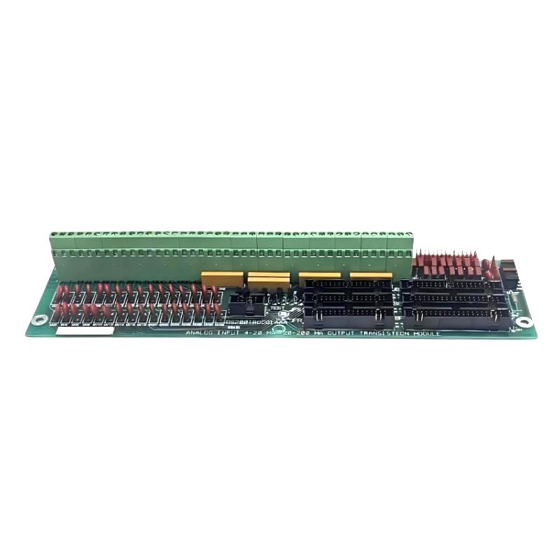
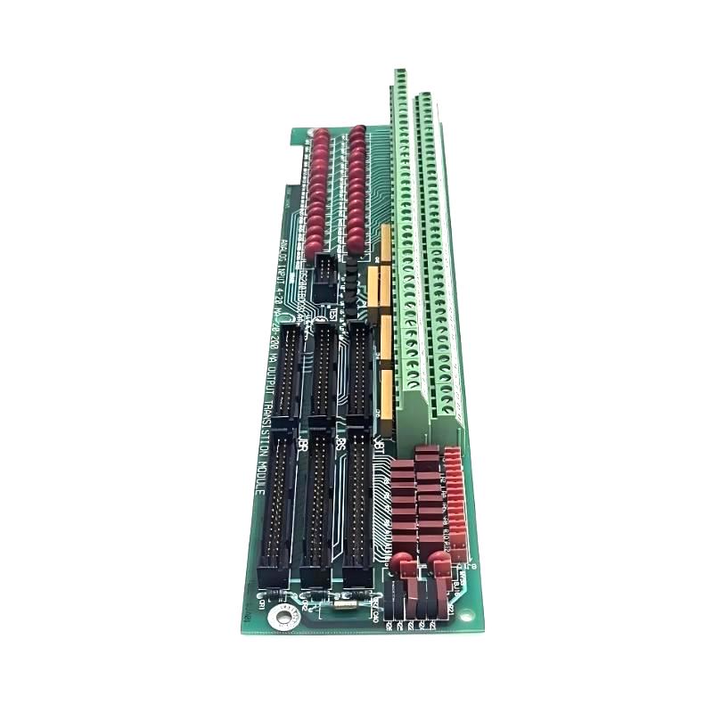
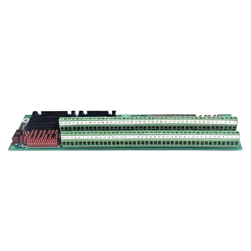
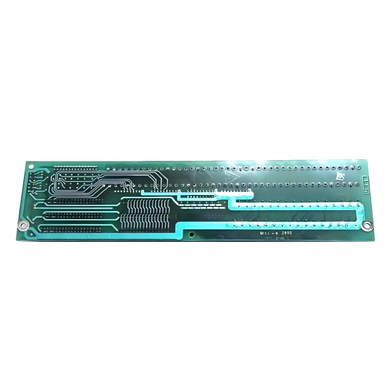
- GE
- DS200TBQCG1AAA
- Mark V Analog I/O Terminal Board
- USA
- 260 x 130 x 40 mm
- 0.5 kg
- Xiamen, China
- New & In Stock
- T/T, PayPal, Western Union
- 1 Year
- 1-3 Working Days
- DHL, UPS, TNT, FedEx and EMS.
- 24-Hour Service
- COO
- 54
Our advantage

Global Logistics
We have a 10-year logistics and express cooperation agreement, so our products can be shipped to any place in the world.

Brand new and original
Our products are imported in bulk from the place of origin. Because of the cooperative relationship, our products are all original and 100% new.

24-hour service
We provide 7*24 hours service to our customers. We will be there whenever you need us.

Price advantage
All our products are priced very favorably because we have our own warehouse and supply.
| Company Information | |||
| [email protected] | |||
| Mobile | +8615980777398 | ||
| +8615980777398 | |||
| 15980777398 |
Product Overview
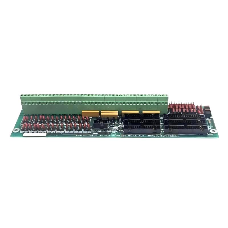
The GE DS200TBQCG1AAA Mark V Analog I/O Terminal Board is an industrial signal-termination component designed for compatible GE Mark V control systems. It provides an organized interface between field instrumentation and the associated analog I/O and control electronics.
In a Mark V installation, terminal boards are an important part of the signal path because they provide the physical connection point for field wiring before signals reach the control and processing circuitry. Analog I/O systems can handle continuously varying measurements and control signals, making reliable termination essential for accurate process monitoring and stable equipment operation.
The supplied dimensions for the DS200TBQCG1AAA are 260 × 130 × 40 mm, with a stated weight of 0.5 kg.
Technical Specifications
| Parameter | Details |
|---|---|
| Manufacturer | GE |
| Model | DS200TBQCG1AAA |
| Product Type | Mark V Analog I/O Terminal Board |
| Control Platform | GE Mark V |
| Main Function | Analog I/O Signal Termination |
| Application | Industrial Automation and Turbine Control |
| Interface | Field Instrumentation / Control-System I/O |
| Installation | Industrial Control Cabinet |
| Dimensions | 260 × 130 × 40 mm |
| Weight | 0.5 kg |
Function and Working Principle
The DS200TBQCG1AAA serves as an interface between field instrumentation and the control-system electronics.
A simplified signal path is:
Field Sensor / Transmitter → DS200TBQCG1AAA → Analog I/O Electronics → Mark V Control Processor
Depending on the system configuration, analog signals can represent continuously changing process variables such as:
- Pressure
- Temperature
- Flow
- Level
- Speed
- Position
- Electrical measurements
- Process-transmitter signals
The terminal board itself primarily provides the physical termination and routing interface. Signal conditioning, conversion, scaling, and control calculations are performed by the associated electronics.
GE’s broader Mark-family analog I/O architecture supports voltage and current input configurations, including common industrial ranges such as 1–5 VDC and 0–20 mA, with configuration dependent on the specific I/O implementation.
Mark V Control-System Integration
The DS200TBQCG1AAA belongs to the family of terminal-board hardware used within the modular Mark V control architecture.
A typical arrangement is:
Field Instrumentation
↓
Analog I/O Terminal Board
↓
I/O / Signal-Conditioning Electronics
↓
Control Processor
↓
Control, Monitoring and Protection Functions
This architecture separates field wiring from processor-level electronics, making signal distribution more organized and allowing technicians to troubleshoot individual sections of the measurement chain.
Analog I/O Applications
Analog I/O is used when a process variable can take a continuous range of values.
Examples include:
Pressure Monitoring
Pressure transmitters can provide continuously varying electrical signals corresponding to process pressure.
Temperature Monitoring
Temperature-related transmitters can provide analog signals representing process or equipment temperature.
Flow Measurement
Flow transmitters can send continuously changing signals to the control system.
Level Measurement
Tank, vessel, and process-level transmitters can be connected through analog I/O interfaces.
Speed and Process Feedback
Analog feedback signals can also be used for equipment-speed or other continuously varying process measurements.
Main Features
Analog Signal Termination
The DS200TBQCG1AAA provides an organized termination point for analog field wiring.
This supports:
- Clear channel identification
- Organized cabinet wiring
- Easier maintenance
- Simplified signal tracing
- Reduced wiring confusion
Mark V System Compatibility
The board is identified as a Mark V Analog I/O Terminal Board, making it suitable for compatible GE Mark V control-system installations.
Because Mark V systems can contain different terminal-board and I/O configurations, the complete part number and system documentation should always be checked before substitution.
Compact Industrial Construction
The supplied dimensions are:
260 × 130 × 40 mm
The stated weight is:
0.5 kg
This form factor allows the terminal board to be integrated into industrial control cabinets and modular control assemblies.
Industrial Applications
The DS200TBQCG1AAA can be used in compatible industrial control environments such as:
- Gas turbine control
- Steam turbine control
- Generator systems
- Power-generation equipment
- Industrial process control
- Rotating machinery
- Manufacturing automation
- Auxiliary equipment monitoring
Installation Guide
Step 1 – Verify the Replacement
Before installing the DS200TBQCG1AAA:
- Confirm the complete part number.
- Verify the Mark V system configuration.
- Compare terminal arrangements.
- Check board revision information.
- Inspect the replacement for physical damage.
- Confirm compatibility with associated I/O electronics.
Do not use physical appearance alone to determine compatibility.
Step 2 – Shut Down and Isolate the System
Before servicing the terminal board:
- Shut down the applicable equipment.
- Isolate electrical power.
- Follow site lockout/tagout procedures.
- Verify that relevant circuits are safe.
- Apply suitable ESD protection when working around electronic assemblies.
Field instruments may have independent power supplies, so all relevant circuits should be identified before disconnecting wiring.
Step 3 – Document Existing Wiring
Before removing the existing board:
- Record terminal numbers.
- Label field wires.
- Record signal types.
- Document channel assignments.
- Photograph the original installation if appropriate.
- Record any configuration information.
Accurate documentation is particularly important when multiple analog channels are present.
Step 4 – Remove the Existing Board
Carefully:
- Verify that all wires are identified.
- Disconnect field wiring.
- Disconnect applicable board-level connections.
- Remove mounting hardware.
- Remove the terminal board.
- Place the removed component on an ESD-safe surface.
Step 5 – Install the DS200TBQCG1AAA
Install the replacement by:
- Aligning the mounting points.
- Securing the board.
- Reconnecting the appropriate connectors.
- Reconnecting field wiring.
- Checking every terminal.
- Ensuring cables are properly routed.
Do not force connectors or terminals into an incorrect position.
Commissioning Procedure
After installation, perform a controlled commissioning process.
Wiring Verification
Check:
- Terminal assignments
- Signal polarity where applicable
- Field-wire integrity
- Connector seating
- Grounding
- Shielding
Analog Input Verification
Check:
- Expected input signal
- Channel identification
- Signal stability
- Controller indication
- Engineering-unit scaling
System Verification
Confirm:
- Normal diagnostic status
- No unexpected alarms
- Correct process-variable display
- Stable operation
- Correct response from associated control functions
Common Failure Symptoms
| Symptom | Possible Cause |
|---|---|
| Analog input missing | Open field circuit |
| Incorrect process value | Wiring or scaling problem |
| Unstable signal | Loose terminal or interference |
| Multiple channels affected | Common wiring or I/O issue |
| Intermittent reading | Loose connection or damaged cable |
| Incorrect channel reading | Wiring misassignment |
| Controller alarm | Signal/interface fault |
Troubleshooting Guide
Analog Signal Missing
If an analog channel does not show a valid value:
- Check the field transmitter.
- Inspect field wiring.
- Verify terminal assignment.
- Check connector seating.
- Verify associated I/O circuitry.
- Review Mark V diagnostics.
The terminal board should not automatically be identified as the fault source.
Incorrect Analog Reading
If the displayed process value is incorrect:
- Check the field transmitter.
- Verify terminal assignment.
- Check signal polarity.
- Verify signal range.
- Check scaling configuration.
- Inspect wiring continuity.
- Compare the field signal with an independent measurement.
A wiring or configuration error can produce the same symptom as a defective board.
Unstable Analog Signal
Possible causes include:
- Loose terminal connections
- Damaged field wiring
- Electrical interference
- Poor shielding
- Grounding problems
- Vibration
- Connector contamination
Inspect the entire signal path from the transmitter to the controller.
Multiple Channels Fail Simultaneously
If several analog channels become unavailable at the same time:
- Check common connections.
- Inspect shared wiring.
- Check associated I/O electronics.
- Verify control-system power.
- Review system diagnostics.
- Inspect the terminal board.
A common upstream or downstream problem is often more likely than several independent field-device failures.
Physical Inspection
Inspect the DS200TBQCG1AAA for:
- Damaged terminals
- Loose terminal hardware
- Cracked components
- Burn marks
- Discoloration
- Corrosion
- Damaged connectors
- Cracked solder joints
- Contamination
- Mechanical deformation
Terminal-board problems can sometimes be identified visually before detailed electrical testing begins.
Preventive Maintenance
Recommended maintenance activities include:
- Periodic terminal inspection
- Field-wiring inspection
- Connector inspection
- Cabinet cleaning
- Corrosion checks
- Grounding inspection
- Signal-trend monitoring
- Review of recurring analog-input alarms
For older control systems, maintaining accurate wiring records is also extremely valuable for future troubleshooting.
Analog Signal Integrity
Analog signals can be sensitive to electrical noise and installation conditions.
For reliable operation:
- Keep analog wiring properly organized.
- Separate sensitive signal wiring from high-power conductors where appropriate.
- Maintain proper shielding.
- Verify grounding arrangements.
- Keep terminal connections secure.
- Minimize mechanical stress on field cables.
A poor connection or noisy installation can cause signal fluctuations that may initially appear to be an I/O hardware failure.
GE’s analog I/O architecture includes configurable voltage/current input arrangements and filtering at the I/O level, illustrating why correct signal type, wiring, and configuration must be considered together during commissioning and troubleshooting.
System Integration
The DS200TBQCG1AAA forms part of a larger industrial control architecture.
| Component | Typical Function |
|---|---|
| Field Sensor | Measures process condition |
| Transmitter | Converts measurement into electrical signal |
| DS200TBQCG1AAA | Terminates and routes analog wiring |
| I/O Electronics | Conditions and processes signal |
| Control Processor | Executes control logic |
| Operator Interface | Displays process information |
| Protection System | Responds to abnormal conditions |
The terminal board should therefore be evaluated as one element of the complete signal chain.
Key Advantages
- Designed for Mark V analog I/O applications
- Provides organized field-signal termination
- Supports industrial instrumentation
- Simplifies signal tracing and maintenance
- Helps organize control-cabinet wiring
- Suitable for turbine and process-control environments
- Compact 260 × 130 × 40 mm design
- Stated weight of 0.5 kg
Technical FAQs
What is the GE DS200TBQCG1AAA?
The GE DS200TBQCG1AAA is a Mark V Analog I/O Terminal Board designed to provide an interface between field analog instrumentation and compatible GE control-system I/O electronics.
What is its main function?
Its main function is to provide organized termination and routing for analog field signals within the Mark V control architecture.
What types of signals can an analog I/O system handle?
Depending on the associated I/O electronics, analog systems can handle continuously varying voltage and current signals used for process measurements and control. GE documentation describes configurations including 1–5 VDC and 0–20 mA.
Is the DS200TBQCG1AAA itself a processor?
No. It is a terminal board, not a standalone control processor. Signal processing and control functions are performed by associated electronics.
What are the dimensions?
The supplied dimensions are 260 × 130 × 40 mm.
What is the weight?
The supplied weight is 0.5 kg.
What causes analog I/O problems?
Possible causes include incorrect wiring, loose terminals, damaged field cables, incorrect signal configuration, electrical interference, faults in associated I/O electronics, or problems elsewhere in the control system.
Should the board be replaced immediately when an analog channel fails?
No. The field transmitter, wiring, terminal connections, associated I/O electronics, and controller configuration should be checked systematically before replacing the terminal board.
Conclusion
The GE DS200TBQCG1AAA Mark V Analog I/O Terminal Board is a field-interface component designed to organize and terminate analog instrumentation signals within compatible GE Mark V control systems.
Its role is important in applications where reliable acquisition of continuously varying process measurements is required. Proper terminal identification, secure wiring, correct signal configuration, and good signal-routing practices are essential for dependable operation.
With supplied dimensions of 260 × 130 × 40 mm and a weight of 0.5 kg, the DS200TBQCG1AAA provides a compact terminal-interface solution for industrial control cabinets.
For maintenance engineers and automation technicians, systematic troubleshooting should always consider the entire signal path—from the field transmitter and wiring through the terminal board and I/O electronics to the Mark V control processor—rather than assuming that a faulty reading is caused by the terminal board alone.