Product Overview
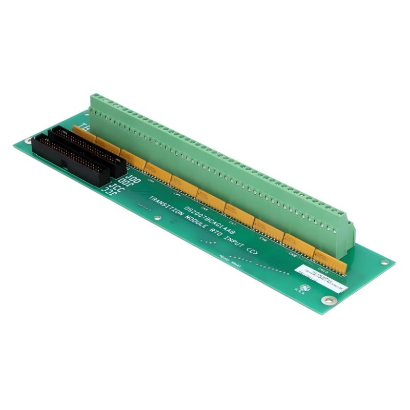
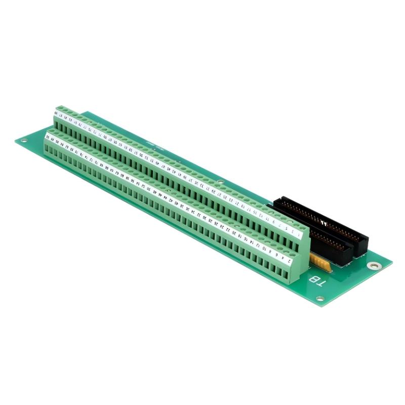
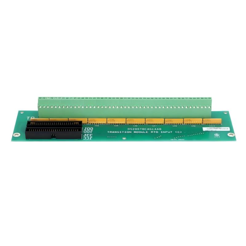
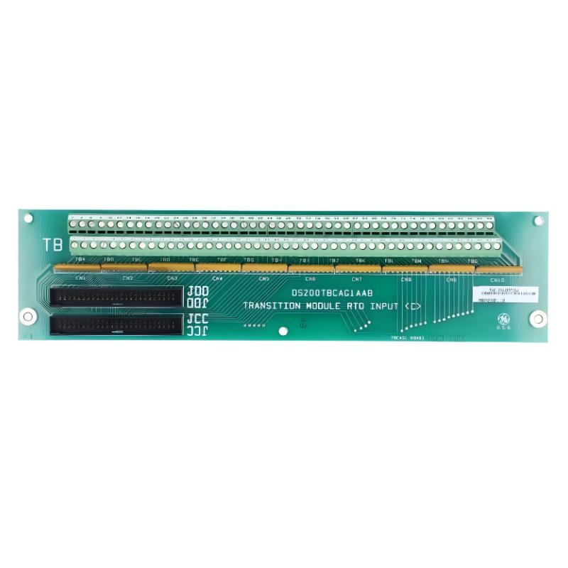
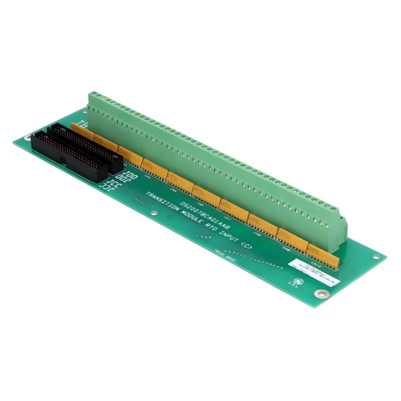
The GE DS200TBCAG1AAB Analog I/O Terminal Block is an industrial terminal interface component designed for connecting analog field signals to compatible GE control-system I/O circuitry. It provides an organized termination point between field wiring and the control system, helping simplify signal distribution, inspection, and maintenance.
Analog I/O terminal blocks are particularly important in industrial automation because process variables such as temperature, pressure, flow, level, speed, and electrical measurements often require continuous signal transmission rather than simple ON/OFF status signals.
The DS200TBCAG1AAB provides a structured connection point for these types of signals within a compatible GE control architecture. Its stated dimensions are 210 × 100 × 35 mm, with a weight of 0.295 kg, making it suitable for installation inside industrial control cabinets and terminal assemblies.
Technical Specifications
| Parameter |
Details |
| Manufacturer |
GE |
| Model |
DS200TBCAG1AAB |
| Product Type |
Analog I/O Terminal Block |
| Series |
GE Industrial Control |
| Main Function |
Analog Signal Termination |
| Signal Type |
Analog I/O |
| Application |
Industrial Automation and Control |
| Installation |
Control Cabinet / Terminal Assembly |
| Interface Function |
Field Wiring and I/O Interface |
| Dimensions |
210 × 100 × 35 mm |
| Weight |
0.295 kg |
Function and Working Principle
The DS200TBCAG1AAB provides a physical termination point between field devices and the control-system I/O circuitry.
A simplified signal path is:
Field Sensor → Field Wiring → DS200TBCAG1AAB → I/O Circuitry → Control Processor
For output signals, the direction is reversed:
Control Processor → I/O Circuitry → DS200TBCAG1AAB → Field Device
Depending on the system configuration, analog signals may represent continuously varying process parameters such as:
- Temperature
- Pressure
- Flow
- Level
- Speed
- Position
- Voltage
- Current
The terminal block itself primarily provides the physical connection and organization of these signals; signal conversion and processing are handled by the associated I/O electronics.
Analog I/O Interface
Analog signals allow a control system to represent continuously changing process conditions.
For example, a sensor may produce a changing electrical signal corresponding to a physical measurement. The signal travels through field wiring to the terminal interface and then to the appropriate I/O circuitry.
A typical architecture is:
Process Variable → Sensor/Transmitter → Terminal Block → Analog I/O Module → Controller → Control Output
This arrangement provides a clear separation between field wiring and control electronics.
Main Features
Organized Analog Signal Termination
The terminal block provides a structured location for connecting analog field wiring.
Benefits include:
- Easier wiring identification
- Simplified maintenance
- Improved cabinet organization
- Faster troubleshooting
- Reduced wiring confusion
Industrial I/O Integration
The DS200TBCAG1AAB can form part of a larger industrial control system containing:
- Analog input channels
- Analog output channels
- Signal-conditioning circuits
- Control processors
- Field sensors
- Actuators
Correct terminal identification and wiring are essential for accurate signal transmission.
Compact Cabinet Installation
The stated dimensions are:
210 × 100 × 35 mm
With a stated weight of:
0.295 kg
the terminal block is suitable for compact industrial control cabinets where space and wiring organization are important.
Industrial Applications
The GE DS200TBCAG1AAB can be used in compatible industrial automation environments, including:
- Power generation
- Turbine control
- Process automation
- Manufacturing systems
- Motor and drive control
- Chemical processing
- Oil and gas equipment
- Water treatment
- Heavy industrial machinery
Installation Guide
Step 1 – Verify the Terminal Block
Before installation:
- Confirm the complete model number.
- Verify the terminal configuration.
- Compare connector and terminal positions.
- Confirm system compatibility.
- Inspect the component for physical damage.
Step 2 – Shut Down the Control System
Before wiring or replacing the terminal block:
- Shut down the applicable equipment.
- Isolate electrical power.
- Follow lockout/tagout procedures.
- Verify that circuits are safe to work on.
- Use ESD protection when working near electronic modules.
Step 3 – Document Existing Wiring
Before disconnecting the existing terminal block:
- Label each wire.
- Record terminal numbers.
- Document signal types.
- Note polarity where applicable.
- Photograph the wiring arrangement when appropriate.
This is especially important for analog signals because incorrect polarity or channel assignment can produce inaccurate measurements.
Step 4 – Remove the Existing Terminal Block
Carefully:
- Disconnect field wiring.
- Verify that all wires are correctly identified.
- Remove mounting hardware.
- Remove the terminal block.
- Inspect the surrounding wiring and mounting area.
Step 5 – Install the DS200TBCAG1AAB
Install the replacement by:
- Aligning the mounting points.
- Securing the terminal block.
- Reconnecting each wire to the correct terminal.
- Checking polarity.
- Confirming that no wire is loose.
- Maintaining proper cable routing.
Avoid excessive tightening that could damage terminals or conductors.
Step 6 – Verify Wiring
Before restoring power:
- Compare every connection with the wiring documentation.
- Verify channel assignments.
- Check polarity.
- Inspect for short circuits.
- Confirm that no bare conductor is exposed improperly.
- Verify that terminal hardware is secure.
Commissioning and Testing
After installation, perform a structured test.
Analog Input Testing
Verify:
- Sensor connection
- Signal continuity
- Correct channel
- Expected input range
- Stable measurement
- Controller reading
Analog Output Testing
For output channels:
- Verify the control command.
- Check the appropriate output channel.
- Confirm field-device response.
- Verify signal stability.
- Confirm that the controlled device responds correctly.
Common Failure Symptoms
| Symptom |
Possible Cause |
| Analog input missing |
Loose or disconnected wiring |
| Incorrect process value |
Wrong channel or polarity |
| Unstable signal |
Loose terminal or interference |
| Analog output unavailable |
Wiring or I/O circuit problem |
| Incorrect channel reading |
Wiring misassignment |
| Intermittent signal |
Poor terminal connection |
| Multiple channels affected |
Power, common wiring, or I/O issue |
Troubleshooting Guide
Analog Input Failure
If an analog input is not detected:
- Inspect the field sensor.
- Check wiring continuity.
- Verify terminal connections.
- Confirm channel assignment.
- Check the associated I/O module.
- Review controller diagnostics.
Incorrect Analog Reading
If the controller displays an incorrect value:
- Verify sensor calibration.
- Check wiring polarity.
- Confirm the correct terminal.
- Check signal scaling.
- Inspect for grounding problems.
- Verify the associated I/O channel.
An incorrect reading does not necessarily indicate a defective terminal block.
Intermittent Signal
Intermittent analog signals can be caused by:
- Loose terminals
- Damaged conductors
- Poor cable routing
- Electrical interference
- Corroded connections
- Mechanical vibration
Inspect the complete signal path rather than replacing the terminal block immediately.
Analog Output Problem
If an analog output does not reach the field device:
- Verify the controller command.
- Check the I/O module.
- Inspect terminal connections.
- Verify output wiring.
- Check the connected device.
- Review system diagnostics.
Physical Inspection
Inspect the DS200TBCAG1AAB for:
- Cracked terminal housings
- Damaged terminals
- Loose screws
- Corrosion
- Discolored areas
- Broken wire connections
- Mechanical deformation
- Contamination
Any terminal showing significant physical damage should be evaluated before continued operation.
Preventive Maintenance
Recommended maintenance includes:
- Periodic terminal inspection
- Checking wire tightness
- Inspecting field wiring
- Cleaning the control cabinet
- Checking for corrosion
- Monitoring abnormal analog values
- Inspecting cable routing
- Reviewing recurring I/O alarms
Maintaining clean and secure terminal connections is especially important for low-level analog signals.
Signal Integrity Considerations
Analog signals can be more sensitive to wiring and environmental conditions than simple digital signals.
For reliable operation:
- Keep signal wiring properly routed.
- Avoid unnecessary proximity to high-power cables.
- Maintain appropriate shielding practices.
- Check grounding arrangements.
- Minimize loose connections.
- Use appropriate cable types for the application.
Signal integrity problems can appear as unstable, noisy, drifting, or inaccurate measurements.
System Integration
The DS200TBCAG1AAB operates as part of a larger analog I/O architecture.
| Component |
Typical Function |
| Field Sensor |
Measures process variable |
| Transmitter |
Produces electrical signal |
| Analog I/O Terminal Block |
Provides field termination |
| Analog I/O Module |
Receives or generates analog signals |
| Control Processor |
Processes control logic |
| Operator Interface |
Displays process information |
| Actuator |
Performs controlled action |
Correct wiring between each component is essential for reliable process monitoring and control.
Key Advantages
- Designed for analog I/O termination
- Provides organized field wiring connections
- Supports industrial control-system integration
- Simplifies wiring inspection
- Facilitates troubleshooting
- Compact 210 × 100 × 35 mm design
- Lightweight 0.295 kg construction
- Suitable for industrial control cabinets
Technical FAQs
What is the GE DS200TBCAG1AAB?
The GE DS200TBCAG1AAB is an Analog I/O Terminal Block used to provide a structured connection point between field analog signals and compatible control-system I/O circuitry.
What types of signals can be associated with an analog I/O terminal?
Analog I/O systems can be used for continuously varying process measurements such as temperature, pressure, flow, level, speed, voltage, and current.
Is the terminal block responsible for signal processing?
The terminal block primarily provides the physical termination and connection interface. Signal conditioning, conversion, and processing are normally performed by the associated I/O electronics.
What are the dimensions?
The stated dimensions are 210 × 100 × 35 mm.
What is the weight?
The stated weight is 0.295 kg.
What causes unstable analog signals?
Possible causes include loose terminals, damaged wiring, electrical interference, grounding problems, poor shielding, vibration, or faults elsewhere in the signal chain.
Why should analog wiring be documented before replacement?
Analog systems can contain multiple channels with different signal assignments and polarities. Accurate documentation helps prevent incorrect channel connections and erroneous process measurements.
Conclusion
The GE DS200TBCAG1AAB Analog I/O Terminal Block provides an organized and practical interface between field analog wiring and compatible GE industrial control-system I/O circuitry. It plays an important role in maintaining clear signal termination, reliable wiring, and efficient maintenance within industrial automation cabinets.
With stated dimensions of 210 × 100 × 35 mm and a weight of 0.295 kg, the component offers a compact solution for analog signal termination and system integration.
For industrial automation engineers and maintenance technicians, correct terminal identification, secure wiring, appropriate signal-routing practices, and regular inspection are essential for maintaining accurate analog measurements and dependable control-system operation.