
NewsNEWCENTER
Featured products

Contact Us
Allen-Bradley 1746-NT4/B SLC 500 Thermocouple/mV Analog Input Module Installation Guide
2026-07-28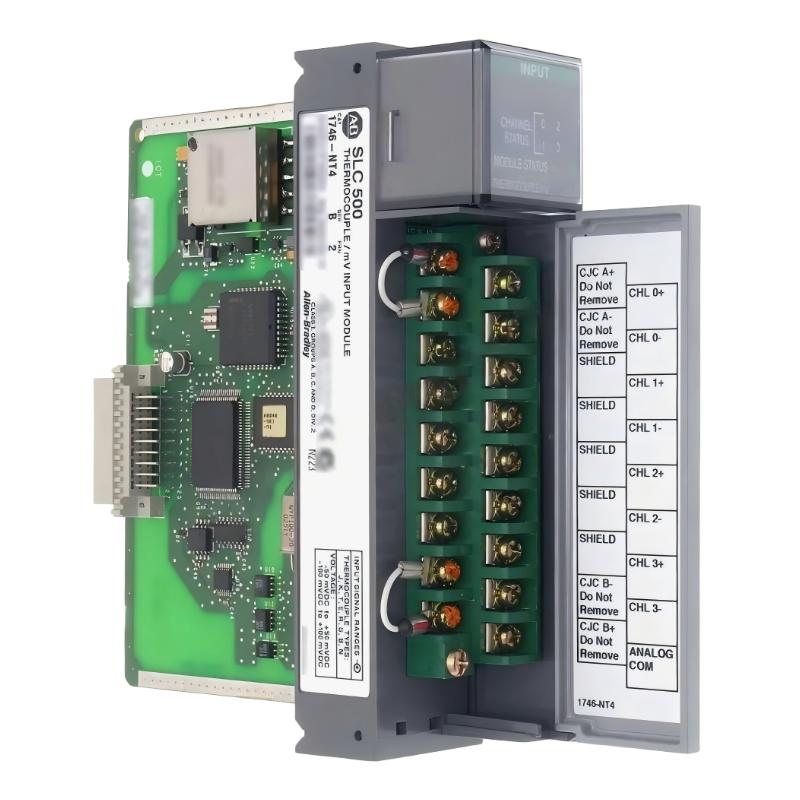
Table of Contents
- 1746-NT4/B Thermocouple/mV Analog Input Module Overview
- Industrial Applications of 1746-NT4/B
- Installation Preparation Requirements
- 1746-NT4/B Hardware Installation Steps
- Thermocouple and mV Input Wiring Procedure
- Channel Configuration and Data Setup
- Temperature Input Testing Procedure
- Startup Commissioning Process
- Engineering Installation Recommendations
- Engineering Summary
1746-NT4/B Thermocouple/mV Analog Input Module Overview
The Allen-Bradley 1746-NT4/B SLC 500 Thermocouple/mV Analog Input Module Installation Guide explains the complete process for hardware installation, sensor connection, parameter configuration, and commissioning of temperature measurement systems.
The 1746-NT4/B is an analog input module designed for SLC 500 PLC systems. It receives thermocouple and millivolt signals from field sensors and converts these signals into digital values for PLC monitoring and process control.
The module is commonly used in industrial applications where accurate temperature measurement and reliable analog signal acquisition are required.
Industrial Applications of 1746-NT4/B
The Allen-Bradley 1746-NT4/B is suitable for various industrial temperature monitoring applications.
- Industrial heating equipment
- Furnace temperature control systems
- Process manufacturing equipment
- Plastic processing machinery
- Food processing systems
- Energy and production monitoring systems
By integrating temperature sensors with the SLC 500 controller, engineers can achieve automatic temperature monitoring, alarm handling, and process regulation.
Installation Preparation Requirements
Before installing the 1746-NT4/B module, engineers should complete the following preparation work:
- Confirm SLC 500 chassis compatibility
- Verify available module installation position
- Identify connected thermocouple types
- Prepare correct sensor cables
- Review electrical drawings
- Check grounding requirements
Proper preparation helps prevent incorrect sensor connection and improves system startup efficiency.
1746-NT4/B Hardware Installation Steps
The 1746-NT4/B module is installed into an available SLC 500 chassis slot and communicates with the processor through the system backplane.
- Switch off the SLC 500 system power
- Select the correct chassis slot
- Insert the 1746-NT4/B module into the slot
- Confirm secure mechanical connection
- Connect field sensor wiring
- Restore system power
Correct hardware installation provides a stable connection between the analog input module and the PLC control system.
Thermocouple and mV Input Wiring Procedure
Thermocouple and millivolt signals are low-level analog signals, so wiring quality directly affects measurement accuracy.
- Connect each sensor to the correct input channel
- Verify thermocouple polarity
- Use suitable extension cables
- Avoid routing near high-voltage cables
- Check terminal connection quality
- Maintain proper shielding and grounding
1746_NT4B_INSTALL_CHECK

MODEL = 1746-NT4/B

CHECK_01 = MODULE_INSTALLATION
CHECK_02 = SENSOR_TYPE
CHECK_03 = INPUT_WIRING
CHECK_04 = SIGNAL_SHIELDING
CHECK_05 = GROUNDING
During a temperature control system installation, engineers found that the temperature reading was different from the actual process value. After inspection, the sensor wiring polarity was found to be incorrect. Correcting the connection restored accurate measurement.
Channel Configuration and Data Setup
After completing wiring, each input channel must be configured according to the connected temperature sensor type.
- Select the correct thermocouple type
- Configure mV input range when required
- Set input channel parameters
- Verify PLC data mapping
- Check temperature value scaling
Correct configuration ensures that the PLC receives accurate temperature information from each connected sensor.
Temperature Input Testing Procedure
Before production operation, engineers should perform detailed input testing:
- Check each temperature input channel
- Confirm sensor signal response
- Compare displayed values with actual measurement
- Verify stable analog data transmission
- Record test results
Individual channel testing helps identify wiring mistakes, configuration errors, and sensor problems before system operation.
Startup Commissioning Process
A complete commissioning process includes:
- Inspect module installation condition
- Verify all sensor connections
- Apply system power
- Check module operating status
- Monitor temperature input values
- Test process control response
- Complete commissioning documentation
Proper commissioning ensures that the temperature monitoring system operates reliably under actual industrial conditions.
Engineering Installation Recommendations
Recommended installation practices include:
- Use high-quality sensor wiring
- Keep analog cables away from power cables
- Label all temperature channels clearly
- Verify sensor compatibility
- Maintain proper grounding methods
- Save configuration records
Following professional installation methods improves measurement accuracy and reduces future maintenance requirements.
Engineering Summary
The Allen-Bradley 1746-NT4/B SLC 500 Thermocouple/mV Analog Input Module Installation process requires careful attention to module mounting, sensor wiring, channel configuration, and commissioning verification. A correct installation approach ensures accurate temperature measurement, stable analog data acquisition, and reliable operation in industrial automation systems.