
NewsNEWCENTER
Featured products

Contact Us
Allen-Bradley 1746-IV8 SLC 500 DC Input Module Installation Guide
2026-07-27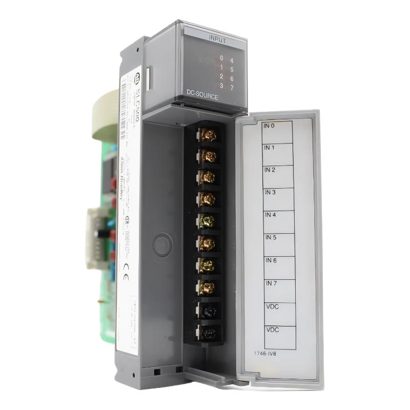
Table of Contents
- 1746-IV8 SLC 500 DC Input Module Overview
- Industrial Applications of 1746-IV8 Input Module
- Installation Preparation and System Requirements
- 1746-IV8 Hardware Installation Procedure
- DC Input Wiring and Field Signal Connection
- Input Module Configuration and Testing
- Startup and Commissioning Process
- Installation Experience and Best Practices
- Frequently Asked Questions
- Engineering Summary
1746-IV8 SLC 500 DC Input Module Overview
The Allen-Bradley 1746-IV8 SLC 500 DC Input Module Installation Guide provides a complete engineering procedure for installing, wiring, configuring, and commissioning the digital input module in industrial automation systems.
The 1746-IV8 is an SLC 500 DC input module designed to collect 24V DC field signals from industrial devices and transfer input status information to the SLC 500 controller system.
The module is commonly used for monitoring sensors, switches, limit devices, proximity detectors, and other digital field signals in machine automation and process control applications.
Correct installation of the 1746-IV8 is essential because incorrect wiring, improper power connection, or configuration errors may cause input signal loss and system alarms.
Industrial Applications of 1746-IV8 Input Module
The Allen-Bradley 1746-IV8 SLC 500 DC Input Module is widely used in industrial environments requiring reliable digital signal monitoring.
- Machine automation systems
- Production line monitoring
- Packaging equipment
- Material handling systems
- Industrial safety monitoring applications
- Process control equipment
The module allows the SLC 500 controller to receive field status information and make control decisions based on real-time input conditions.
Installation Preparation and System Requirements
Before installing the 1746-IV8 input module, engineers should complete the following preparation work:
- Confirm SLC 500 chassis compatibility
- Verify available installation slot
- Review electrical wiring drawings
- Confirm DC field signal voltage
- Prepare terminal wiring information
- Check cabinet environmental conditions
Proper preparation helps prevent wiring mistakes and improves commissioning efficiency.
1746-IV8 Hardware Installation Procedure
The 1746-IV8 module is installed into an available slot of the SLC 500 chassis and communicates with the processor through the system backplane.
- Turn off system power before installation
- Select the correct chassis slot
- Insert the 1746-IV8 module carefully
- Secure the module connection
- Connect field wiring terminals
- Restore system power
Correct installation ensures stable communication between the input module and the SLC 500 processor.
DC Input Wiring and Field Signal Connection
Proper field wiring is critical for reliable input signal detection.
- Connect DC input devices according to wiring diagrams
- Verify input signal polarity
- Check common terminal connections
- Confirm sensor power supply
- Inspect terminal tightening condition
- Maintain proper grounding practices
1746_IV8_INSTALL_CHECK

MODEL = 1746-IV8

CHECK_01 = SLC_SLOT_INSTALLATION
CHECK_02 = INPUT_WIRING
CHECK_03 = DC_POWER
CHECK_04 = SENSOR_CONNECTION
CHECK_05 = TERMINAL_SECURITY
During one industrial installation project, engineers found that several input points were not detected after startup. Investigation showed that the field sensor wiring polarity was incorrect. After correcting the wiring, all input channels returned to normal operation.
Input Module Configuration and Testing
After hardware installation, engineers should configure and test the 1746-IV8 module in the SLC 500 control system.
- Add the input module to the controller configuration
- Verify input address assignment
- Check input status monitoring
- Confirm processor communication
- Test field signal response
Correct configuration ensures that the controller accurately receives field device status information.
Startup and Commissioning Process
A complete commissioning procedure includes:
- Inspect module installation
- Check all input wiring connections
- Apply system power
- Verify module status indicators
- Activate field input devices
- Confirm PLC input response
- Record commissioning results
Each input channel should be tested individually to ensure accurate signal detection before production operation.
Installation Experience and Best Practices
Common installation considerations for the 1746-IV8 include:
- Use clear field wiring labels
- Separate signal cables from high-power wiring
- Check sensor voltage compatibility
- Ensure secure terminal connections
- Maintain cabinet organization
- Document wiring changes
Following professional installation practices improves signal reliability and reduces future troubleshooting requirements.
Frequently Asked Questions
What is the function of the 1746-IV8?
The 1746-IV8 receives DC digital signals from field devices and transfers input information to the SLC 500 controller.
Why are wiring checks important during installation?
Incorrect polarity, loose terminals, or wrong connections may prevent the controller from detecting field signals correctly.
What should be verified before startup?
Engineers should check module installation, input wiring, power supply, configuration, and field device operation.
Engineering Summary
The Allen-Bradley 1746-IV8 SLC 500 DC Input Module Installation process requires careful attention to hardware mounting, DC signal wiring, controller configuration, and commissioning tests. Proper installation ensures reliable field signal acquisition, stable PLC communication, and long-term performance in industrial automation applications.