
NewsNEWCENTER
Featured products

Contact Us
Allen-Bradley 1746-HSTP1/E SLC 500 Stepper Controller Module Installation Guide
2026-07-24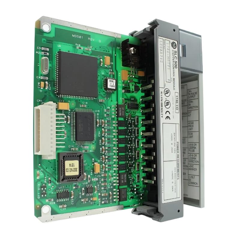
Table of Contents
- 1746-HSTP1/E SLC 500 Stepper Controller Module Overview
- Industrial Applications of 1746-HSTP1/E
- Installation Preparation and System Requirements
- 1746-HSTP1/E Hardware Installation Procedure
- Stepper Motor Wiring and Signal Connection
- Motion Parameter Configuration
- Startup and Commissioning Process
- Installation Experience and Best Practices
- Frequently Asked Questions
- Engineering Summary
1746-HSTP1/E SLC 500 Stepper Controller Module Overview
The Allen-Bradley 1746-HSTP1/E SLC 500 Stepper Controller Module Installation Guide provides a complete engineering procedure for installing, wiring, configuring, and commissioning the stepper motion control module in industrial automation systems.
The 1746-HSTP1/E is a single-axis stepper controller module designed for the SLC 500 PLC platform. It provides pulse and direction control signals for stepper motor applications and allows precise position and velocity control in machine automation systems.
The module integrates with SLC 500 processors through the backplane and supports motion functions including absolute moves, incremental moves, homing operations, and position monitoring. :contentReference[oaicite:0]{index=0}
Industrial Applications of 1746-HSTP1/E
The Allen-Bradley 1746-HSTP1/E Stepper Controller Module is widely used in applications requiring accurate single-axis positioning control.
- CNC positioning systems
- Packaging machinery
- Assembly equipment
- Material handling systems
- Indexing machines
- Precision automation equipment
The module provides a practical solution for controlling stepper motor systems where accurate motion positioning and repeatability are required.
Installation Preparation and System Requirements
Before installing the 1746-HSTP1/E module, engineers should complete the following preparation work:
- Confirm SLC 500 chassis compatibility
- Verify processor communication requirements
- Prepare stepper drive and motor information
- Review motion control wiring drawings
- Confirm external power requirements
- Prepare grounding and shielding plans
Proper preparation helps prevent wiring errors and reduces commissioning time.
1746-HSTP1/E Hardware Installation Procedure
The 1746-HSTP1/E module is installed into an available SLC 500 chassis slot and communicates with the processor through the backplane.
- Power off the SLC 500 chassis
- Select the correct installation slot
- Insert the 1746-HSTP1/E module securely
- Check module seating condition
- Restore system power
- Verify module status indicators
Correct installation ensures reliable communication between the SLC processor and motion controller module.
Stepper Motor Wiring and Signal Connection
Proper wiring is critical for stable stepper motor operation. The 1746-HSTP1/E provides motion output signals that connect to external stepper drives or translators.
- Connect pulse output signals
- Connect direction control signals
- Connect encoder feedback if required
- Connect home and limit switch inputs
- Verify emergency stop wiring
- Check cable shielding and grounding
1746_HSTP1_INSTALL_CHECK

MODEL = 1746-HSTP1/E

CHECK_01 = SLC_BACKPLANE
CHECK_02 = STEP_SIGNAL
CHECK_03 = DIRECTION_SIGNAL
CHECK_04 = MOTOR_CONNECTION
CHECK_05 = INPUT_DEVICES
During one machine installation project, engineers found that the stepper motor moved in the wrong direction during testing. Investigation showed that the direction signal wiring was reversed. After correcting the connection, the motion system operated correctly.
Motion Parameter Configuration
After hardware installation, engineers must configure motion parameters according to application requirements.
- Set movement distance parameters
- Configure velocity settings
- Define acceleration and deceleration values
- Configure homing functions
- Set input limit conditions
- Verify position commands
The 1746-HSTP1/E supports different motion command methods, including absolute and incremental positioning operations. :contentReference[oaicite:1]{index=1}
Startup and Commissioning Process
A complete commissioning procedure includes:
- Check all wiring connections
- Apply system power
- Verify module communication
- Test stepper drive response
- Perform homing operation
- Execute positioning tests
- Confirm motion accuracy
Engineers should gradually increase motion speed during testing to verify stable operation and prevent mechanical damage.
Installation Experience and Best Practices
Common installation considerations include:
- Use shielded motion cables
- Separate power and signal wiring
- Check motor phase connections carefully
- Verify limit switch operation
- Maintain proper grounding
- Record motion parameters
Following professional installation practices improves positioning accuracy and reduces future maintenance requirements.
Frequently Asked Questions
What is the function of the 1746-HSTP1/E?
The 1746-HSTP1/E provides single-axis stepper motor control for SLC 500 PLC systems.
Can the module control position movement?
Yes. The module supports programmed motion operations including positioning commands and movement control functions.
What should be checked before startup?
Engineers should verify module installation, wiring, motor connection, input devices, and motion parameters.
Engineering Summary
The Allen-Bradley 1746-HSTP1/E SLC 500 Stepper Controller Module Installation process requires careful attention to hardware mounting, motion wiring, parameter configuration, and commissioning testing. Correct installation ensures reliable single-axis motion control, accurate positioning performance, and stable operation in industrial automation applications.