
NewsNEWCENTER
Featured products

Contact Us
Allen-Bradley 1734-OB2E Point I/O 2-Point Digital Output Module Installation Guide
2026-07-22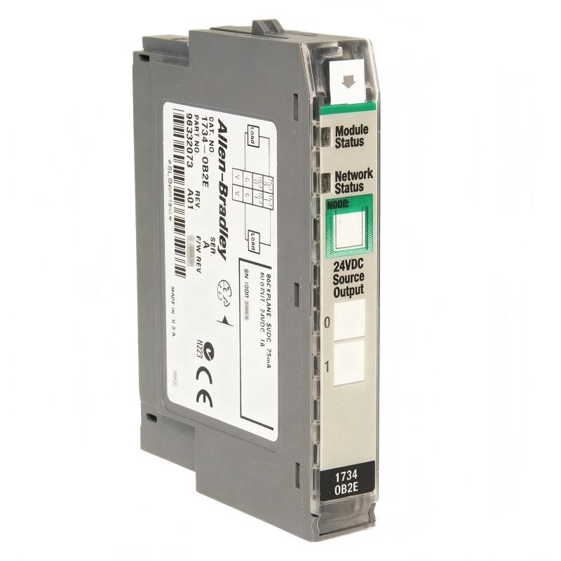
Table of Contents
- 1734-OB2E Point I/O 2-Point Digital Output Module Overview
- Industrial Application of 1734-OB2E Digital Output Module
- Installation Preparation and System Requirements
- 1734-OB2E Module Installation Procedure
- Digital Output Wiring and Terminal Connection
- 1734-OB2E Configuration and I/O Mapping
- Startup and Commissioning Process
- Installation Experience and Best Practices
- Frequently Asked Questions
- Engineering Summary
1734-OB2E Point I/O 2-Point Digital Output Module Overview
The Allen-Bradley 1734-OB2E Point I/O 2-Point Digital Output Module Installation Guide explains the complete process for installing, wiring, configuring, and commissioning the module in distributed industrial automation systems.
The 1734-OB2E is a compact POINT I/O digital output module designed for controlling field devices through industrial control networks. It provides two digital output channels and is typically used with POINT I/O terminal bases and communication adapters to create flexible remote I/O stations.
The module is suitable for applications requiring reliable switching control of industrial loads, including valves, relays, indicators, and other digital devices.
Industrial Application of 1734-OB2E Digital Output Module
The Allen-Bradley 1734-OB2E Point I/O output module is commonly installed in compact automation systems that require distributed digital control.
- Machine control systems
- Packaging equipment
- Assembly automation
- Material handling systems
- Remote actuator control applications
By placing output modules closer to field devices, engineers can reduce control cabinet wiring complexity and improve system expansion flexibility.
Installation Preparation and System Requirements
Before installing the 1734-OB2E module, engineers should prepare the following:
- Confirm POINT I/O system architecture
- Verify compatible terminal base model
- Check controller communication method
- Review output wiring diagrams
- Confirm field device voltage requirements
- Prepare installation tools and labels
Proper preparation reduces wiring mistakes and improves the efficiency of startup commissioning.
1734-OB2E Module Installation Procedure
The 1734-OB2E must be installed correctly on the POINT I/O terminal base to ensure stable electrical connection and reliable operation.
- Install the terminal base on the DIN rail
- Verify terminal base locking position
- Connect field wiring terminals
- Insert the 1734-OB2E output module
- Secure the module locking mechanism
- Check the final installation condition
A correct mechanical installation ensures proper communication between the module, terminal base, and POINT I/O adapter.
Digital Output Wiring and Terminal Connection
The output wiring procedure is one of the most important steps because incorrect connections may cause field devices to operate incorrectly.
- Identify each output channel correctly
- Connect load devices according to electrical drawings
- Verify power supply polarity
- Check common connections
- Tighten all terminal screws
- Confirm cable routing and protection
1734_OB2E_INSTALL_CHECK

MODEL = 1734-OB2E
CHECK = TERMINAL_BASE
CHECK = OUTPUT_CHANNEL
CHECK = FIELD_POWER
CHECK = DEVICE_CONNECTION
During one factory installation, engineers completed the hardware setup but found that one indicator lamp could not be controlled during testing. After inspection, the output cable was connected to the wrong terminal point. Correcting the wiring restored normal operation.
1734-OB2E Configuration and I/O Mapping
After completing hardware installation, the module must be configured in the automation controller system.
- Add the POINT I/O module to the controller configuration
- Assign correct I/O addresses
- Verify output tag mapping
- Check communication status
- Download the updated configuration
Correct I/O mapping ensures that controller commands are transferred accurately to the physical output channels.
Startup and Commissioning Process
A complete 1734-OB2E commissioning procedure includes:
- Inspect all hardware connections
- Apply system power
- Check module status indicators
- Verify controller communication
- Test each output channel
- Confirm field device response
- Record commissioning results
Engineers should perform individual output tests before full production operation to confirm that every connected device responds correctly.
Installation Experience and Best Practices
Common installation considerations for the 1734-OB2E include:
- Use clear terminal labeling
- Separate signal and power wiring properly
- Confirm correct field device ratings
- Check terminal tightening quality
- Maintain proper cabinet organization
Following professional installation practices improves system reliability and reduces future troubleshooting time.
Frequently Asked Questions
What is the main function of the 1734-OB2E?
The 1734-OB2E provides two digital output channels for controlling industrial field devices in POINT I/O systems.
Why does the module require a terminal base?
The terminal base provides the electrical interface between the module and field wiring while allowing easy module replacement.
What should be checked before production startup?
Engineers should verify wiring, module status, I/O configuration, communication, and field device operation.
Engineering Summary
The Allen-Bradley 1734-OB2E Point I/O 2-Point Digital Output Module Installation process requires careful attention to mechanical mounting, wiring accuracy, configuration setup, and commissioning verification. Proper installation ensures reliable digital output control, stable system communication, and long-term performance in industrial automation applications.