
NewsNEWCENTER
Featured products
Contact Us
Allen-Bradley 140G-K3F4-D40 Molded Case Circuit Breaker Installation Guide
2026-06-26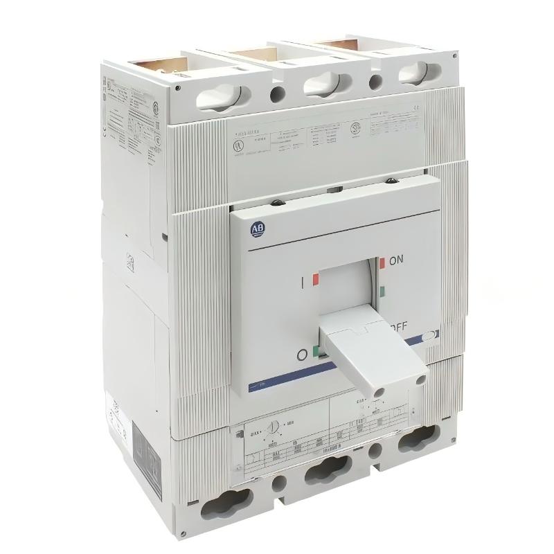
Table of Contents
- Installation Overview of 140G-K3F4-D40 MCCB
- Role in Industrial Power Distribution System
- Pre-Installation Safety & System Isolation
- Mechanical Mounting & Busbar Alignment
- Cable Termination & Torque Requirements
- Thermal-Magnetic Protection Setting Configuration
- Commissioning & Load Verification
- FAQs on 140G-K3F4-D40 Installation
- Engineering Summary & Field Practice
Installation Overview of 140G-K3F4-D40 MCCB
The Allen-Bradley 140G-K3F4-D40 molded case circuit breaker is a 400A K-frame MCCB used in industrial power distribution systems. It provides overload and short-circuit protection for feeder circuits, MCC panels, and heavy motor loads. Proper installation is critical to ensure selectivity and avoid nuisance tripping during transient conditions.
Role in Industrial Power Distribution System
This MCCB acts as a primary protection device in low-voltage distribution networks. It isolates fault conditions, limits damage to downstream equipment, and coordinates with upstream breakers and downstream motor protection devices.
Pre-Installation Safety & System Isolation
- Fully isolate upstream power supply before installation
- Verify absence of voltage using calibrated test equipment
- Confirm short-circuit rating matches system fault level
- Inspect enclosure temperature rating and ventilation conditions
- Ensure correct breaker frame size (K-frame 400A class)
Mechanical Mounting & Busbar Alignment
- Mount breaker securely onto panel base or MCC structure
- Align busbar connection points to avoid mechanical stress
- Ensure phase spacing is uniform and insulated properly
- Verify no external force is applied to breaker terminals
Field experience shows that improper busbar alignment can create localized heating, which later leads to insulation aging and unexpected thermal trips.
Cable Termination & Torque Requirements
- Use correctly rated copper or aluminum cable lugs
- Apply manufacturer-recommended torque values precisely
- Avoid under-torque (heating risk) and over-torque (terminal damage)
- Ensure balanced phase cable routing to minimize current imbalance
INSTALL_CHECK /MODEL=140G-K3F4-D40 /TORQUE_VERIFY /PHASE_BALANCE /THERMAL_RISK_SCAN
Thermal-Magnetic Protection Setting Configuration
- Set thermal trip current according to continuous load (Ir ≈ 280–400A range)
- Configure magnetic trip threshold based on motor inrush or system fault current
- Verify coordination curves with upstream protective devices
- Ensure selectivity with downstream MCC or branch circuits
Incorrect coordination is one of the most common causes of nuisance tripping in K-frame MCCB systems.
Commissioning & Load Verification
- Perform no-load energization test before applying full load
- Gradually increase load while monitoring current balance
- Use thermal imaging to verify terminal heating behavior
- Simulate transient load conditions if motor circuits are present
FAQs on 140G-K3F4-D40 Installation
Can this MCCB operate safely at full 400A continuously?
Yes, but only under proper ambient temperature conditions and correct installation torque. Thermal derating must be considered.
Why does heating occur even when load is within rating?
Loose terminals, unbalanced phases, or poor busbar contact are common causes of localized heating.
Is coordination study required before installation?
Yes. Protection coordination ensures selective tripping and prevents unnecessary upstream shutdowns.
Engineering Summary & Field Practice
The Allen-Bradley 140G-K3F4-D40 molded case circuit breaker is a high-capacity protection device designed for industrial distribution systems. Reliable operation depends on correct mechanical installation, precise torque control, and proper protection coordination. Field experience confirms that most issues are caused by installation and system design errors rather than breaker failure.