
NewsNEWCENTER
Featured products
Contact Us
Yokogawa A2SAM505 Current/Voltage Output Adapter Installation Guide
2026-06-02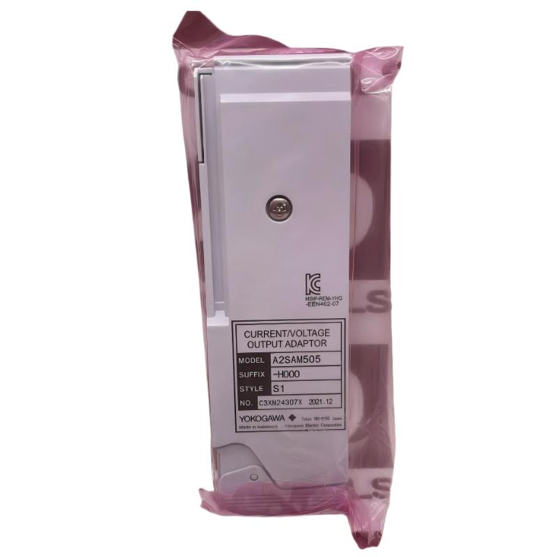
Table of Contents
- A2SAM505 Installation Overview in Yokogawa N-IO System
- Role of A2SAM505 Current/Voltage Output Adapter
- Preparation Before Installation
- Mounting on Base Plate & Mechanical Setup
- Signal Wiring and Output Configuration
- Commissioning & System Verification
- FAQs on A2SAM505 Installation
- Engineering Summary
A2SAM505 Installation Overview in Yokogawa N-IO System
Yokogawa A2SAM505 current/voltage output adapter installation is critical in N-IO and CENTUM VP I/O architectures, where analog output accuracy directly impacts process control stability. In field applications, incorrect mounting or improper load configuration often leads to unstable 4–20 mA loop behavior or voltage drift in 0–10 V signals.
Role of A2SAM505 Current/Voltage Output Adapter
The A2SAM505 functions as a dual-mode analog output adapter supporting both 4–20 mA current output and 0–10 V voltage output. It is commonly used in process industries to interface PLC/DCS systems with actuators, valve positioners, and field instrumentation. Field engineers often rely on it for precise loop control where output stability is critical to maintaining process efficiency.
Preparation Before Installation
- Confirm N-IO node power is isolated before installation
- Verify compatibility with A2MMM843 or supported I/O modules
- Check base plate (A2BN3D) slot allocation
- Inspect AKB cable length and shielding condition
- Ensure correct output range configuration in engineering tool
Mounting on Base Plate & Mechanical Setup
The A2SAM505 must be installed on the designated base plate with proper alignment to avoid backplane communication instability. In one commissioning case, slight misalignment caused intermittent output fluctuation of ±0.3 mA.
- Insert module into assigned slot on A2BN3D base plate
- Ensure locking mechanism fully engages
- Verify vertical alignment with adjacent modules (especially redundant pairs)
- Check physical spacing to avoid thermal accumulation
Signal Wiring and Output Configuration
Correct wiring is essential to ensure stable analog output performance in PLC/DCS systems.
- For voltage output: connect load ≥ 10 kΩ to ensure signal integrity
- For current output: ensure loop resistance within 0–750 Ω range
- Use shielded twisted pair cables for analog signals
- Maintain proper grounding to reduce EMI-induced drift
Engineering specification reference:
Voltage output: 0 to 10 V DC
Current output: 4 to 20 mA DC
Output accuracy: ±12 mV / ±48 μA (typical)
Load resistance: up to 750 Ω (current mode)
In one field installation, improper loop resistance caused a 1.2 mA offset, which was corrected after reducing cable length and improving grounding.
Commissioning & System Verification
During commissioning, engineers should validate both signal accuracy and system response behavior under load conditions.
- Verify output scaling in engineering software
- Perform loop calibration using precision multimeter
- Check step response stability (2 ms update cycle typical)
- Monitor output drift during thermal stabilization
Field experience shows that initial drift of ±0.05 mA may occur during warm-up but stabilizes within 30 minutes of operation.
FAQs on A2SAM505 Installation
Can A2SAM505 be used simultaneously for voltage and current output?
No, output mode must be configured in engineering software before operation. Mixed mode is not supported on a single channel.
What happens if load resistance exceeds specification?
Exceeding 750 Ω in current mode may cause output saturation and incorrect loop readings.
Is shielding necessary for short cable runs?
Yes, even short runs are susceptible to EMI in industrial environments, especially near VFDs.
Engineering Summary
Proper installation of Yokogawa A2SAM505 ensures stable analog output performance in PLC and DCS systems. Field data confirms that most signal instability issues originate from wiring configuration, grounding quality, and load mismatch rather than module failure. Correct commissioning practices significantly improve loop accuracy and long-term system reliability.