

ProductPRODUCT
Featured products
Contact Us
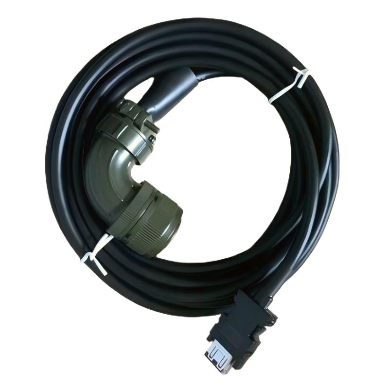
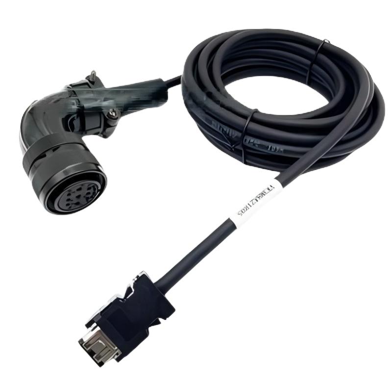
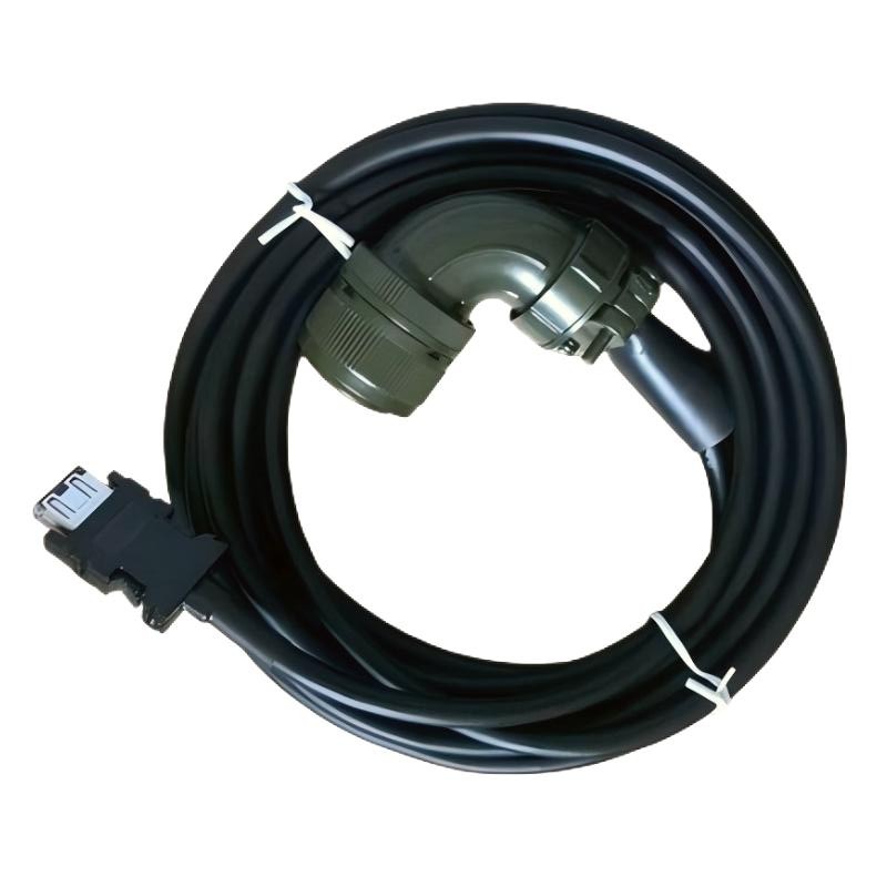
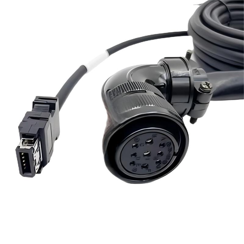
- Schneider
- VW3M8A21R03GJ
- BCH16 Servo Motor Encoder Cable
- France
- 3 meters
- 0.25 kg
- Xiamen, China
- New & In Stock
- T/T, PayPal, Western Union
- 1 Year
- 1-3 Working Days
- DHL, UPS, TNT, FedEx and EMS.
- 24-Hour Service
- COO
- 3
Our advantage

Global Logistics
We have a 10-year logistics and express cooperation agreement, so our products can be shipped to any place in the world.

Brand new and original
Our products are imported in bulk from the place of origin. Because of the cooperative relationship, our products are all original and 100% new.

24-hour service
We provide 7*24 hours service to our customers. We will be there whenever you need us.

Price advantage
All our products are priced very favorably because we have our own warehouse and supply.
| Company Information | |||
| [email protected] | |||
| Mobile | +8615980777398 | ||
| +8615980777398 | |||
| 15980777398 |
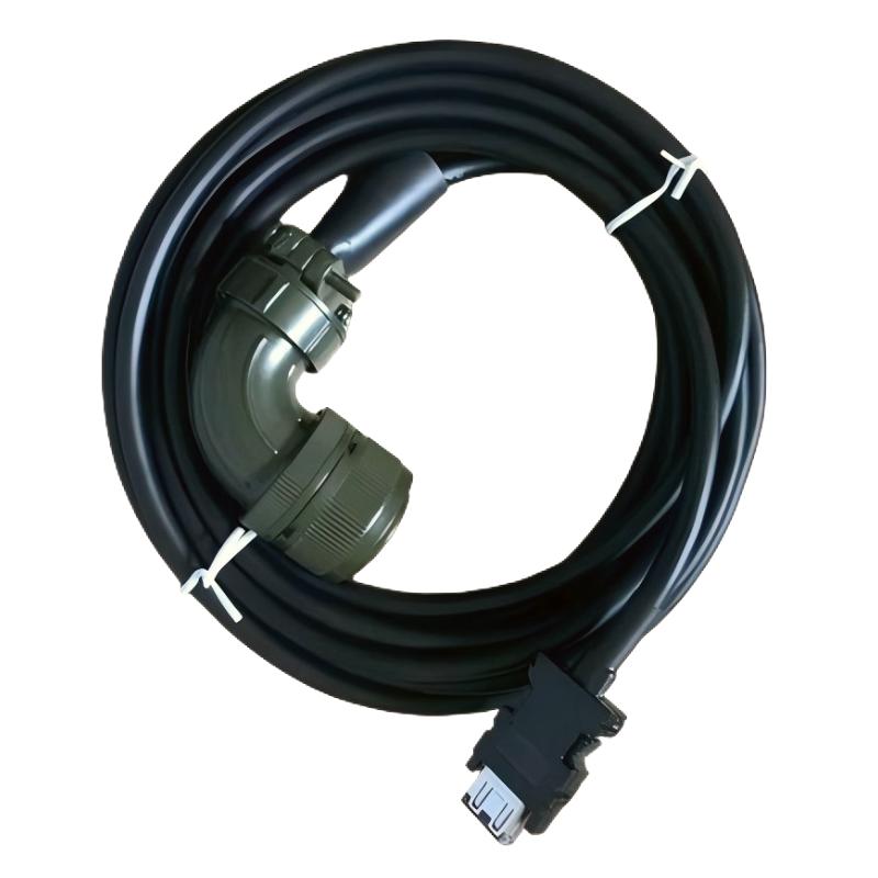
1. Product Overview
The Schneider VW3M8A21R03GJ BCH16 Servo Motor Encoder Cable is an industrial automation cable identified for use in compatible Schneider Electric BCH16 servo motor encoder connection applications. Encoder cables are important components in servo motion-control systems because they provide the connection required for feedback signals between designated motor-side components and compatible control equipment.
In servo-driven machinery, feedback signals help the control system monitor motor position, speed, or other motion-related information, depending on the encoder and drive configuration. A correctly specified encoder cable helps maintain the intended feedback connection and supports reliable communication within the motion-control system.
The VW3M8A21R03GJ has a specified cable length of 3 meters and a weight of 0.25 kg. This length may suit installations where the servo motor and the corresponding connection point are relatively close together, provided the planned cable route meets the equipment manufacturer’s requirements.
When selecting this cable for installation or replacement, engineers should confirm the complete model number, connector arrangement, supported BCH16 servo motor configuration, and compatible drive or controller interface. Similar-looking cables are not necessarily interchangeable, particularly when encoder feedback connections are involved.
2. Technical Specifications
| Parameter | Specification |
|---|---|
| Brand | Schneider Electric |
| Model | VW3M8A21R03GJ |
| Product Type | Servo Motor Encoder Cable |
| Applicable Equipment | BCH16 servo motor applications, subject to configuration verification |
| Cable Length | 3 meters |
| Weight | 0.25 kg |
| Application | Servo motor encoder feedback connection |
| Connection Function | Encoder feedback, subject to model-specific verification |
| Connector Configuration | Confirm from the product label and technical documentation |
| Electrical Characteristics | Verify the requirements of the connected motor and drive |
| Installation Type | Industrial automation and motion-control systems |
| System Compatibility | Confirm the exact motor, drive, and feedback interface before installation |
The cable length and weight above are the supplied product specifications. Connector pin assignments, shielding details, feedback characteristics, and supported equipment combinations should be verified for the exact model before commissioning.
3. Function and Working Principle
A servo motor encoder cable provides the physical connection used to transfer encoder feedback signals between designated components in a servo motion-control system. The encoder detects motion-related information, while the drive or controller uses the available feedback to regulate motor operation according to the system configuration.
The general feedback process can be described in several stages:
- Motion detection: The encoder associated with the servo motor detects motion-related information, such as position or rotational movement.
- Signal transmission: The encoder cable provides the specified electrical path between the encoder and its designated interface.
- Feedback processing: Compatible drive or control equipment receives and processes the feedback signals.
- Motion regulation: The servo system uses the available feedback as part of its control process to achieve the commanded movement.
- Fault monitoring: Depending on the system design, the controller or drive may detect feedback-related abnormalities and report diagnostic information.
The exact feedback format, signal arrangement, and supported communication method depend on the encoder, cable, and connected equipment. These details should not be inferred from the cable model number alone.
Importance of Correct Encoder Cable Selection
Encoder feedback is an important part of closed-loop motion control. An unsuitable cable, incorrect connector arrangement, or damaged conductor may interrupt feedback transmission and cause servo alarms, unstable operation, or failure to enable the motor.
For the VW3M8A21R03GJ, engineers should verify the intended BCH16 application and ensure that the cable matches the required motor and drive interfaces.
4. Role in Servo Motor and Motion-Control Systems
Servo systems rely on coordinated operation between the motor, encoder, drive, controller, and associated wiring. The encoder cable supports the feedback connection required by the specific system architecture.
4.1 Encoder Feedback Transmission
The cable provides the designated connection for encoder feedback signals. Correct cable selection helps maintain the intended signal path between the motor-side feedback device and compatible control equipment.
4.2 Closed-Loop Motion Control
In a closed-loop servo system, feedback is used to compare actual motor behavior with the commanded motion. The controller and drive use this information according to their control algorithms. A correctly installed feedback cable helps preserve the connection required for this process.
4.3 Servo Drive Integration
The encoder cable must match the feedback interface supported by the connected drive. Incorrect cable selection may result in an undetected encoder, feedback errors, or an inability to commission the servo system.
4.4 Equipment Maintenance
When an existing encoder cable is damaged, using the correct replacement helps maintain the original system configuration. Verifying the full model number, cable length, and connector arrangement is particularly important when multiple cables are installed in the same machine.
4.5 Operational Reliability
Reliable feedback connections are important in applications that require repeatable positioning and coordinated motion. Proper cable routing, secure connectors, and periodic inspection help reduce avoidable interruptions.
5. Industrial Applications
The Schneider VW3M8A21R03GJ may be considered for compatible BCH16 servo motor encoder applications after the exact equipment configuration has been verified.
5.1 Automated Manufacturing Machinery
Production machines often use servo motors for controlled positioning, feeding, indexing, and other motion tasks. Encoder feedback helps the control system monitor motor movement and coordinate machine sequences.
5.2 Packaging Equipment
Packaging machinery may use servo-driven mechanisms for material feeding, cutting, sealing, labeling, and product positioning. Suitable encoder cabling helps maintain the feedback connection required by the motion-control design.
5.3 Assembly and Positioning Systems
Automated assembly equipment frequently requires accurate movement and repeatable positioning. Encoder connections allow compatible servo systems to use motion feedback as part of their control process.
5.4 Material Handling Equipment
Servo-driven transfer mechanisms, pick-and-place equipment, and positioning stages depend on correctly configured motion-control components. The encoder cable must be selected according to the installed motor and drive requirements.
5.5 Machine Retrofit and Repair
During equipment repair or modernization, the original encoder cable may need replacement because of wear, damage, or connector deterioration. Confirming the complete VW3M8A21R03GJ part number helps reduce the risk of using an incompatible cable.
These examples describe common servo automation environments. Actual suitability depends on the specific BCH16 motor, drive, and feedback configuration.
6. Installation and System Integration
Correct installation helps protect the cable, maintain the encoder feedback connection, and reduce the risk of intermittent faults. The manufacturer’s model-specific instructions and the site’s electrical safety procedures should always take precedence.
Step 1: Verify the Complete Model Number
Confirm that the cable is identified as VW3M8A21R03GJ. Check the product label and compare it with the original cable, equipment drawings, and approved spare-parts list.
Do not confuse this model with cables that have similar part numbers but different suffixes, connector arrangements, or intended applications.
Step 2: Isolate the Equipment
Place the machine in a safe state and isolate the relevant power sources according to the site’s lockout/tagout procedure. Follow the drive manufacturer’s instructions before disconnecting motor or encoder wiring.
Do not connect or disconnect components while energized unless the equipment documentation explicitly permits the operation.
Step 3: Inspect the Cable and Connectors
Examine the cable jacket, connector housings, locking features, and accessible contacts for signs of damage. Check for cuts, crushed sections, contamination, bent contacts, or deteriorated strain relief.
Do not install a cable that shows visible damage or has an uncertain service history.
Step 4: Confirm Motor and Drive Compatibility
Verify that the cable is intended for the installed BCH16 servo motor configuration and the designated feedback interface. Confirm the connector types and pin assignments using the appropriate technical documentation.
Physical connector fit alone does not establish electrical compatibility.
Step 5: Plan the Cable Route
The cable has a specified length of 3 meters. Plan the route so that it reaches both connection points without being stretched or placed under excessive mechanical stress.
Avoid sharp edges, pinch points, hot surfaces, and areas where moving components may pull or abrade the cable. Follow the specified bend-radius requirements.
Step 6: Separate and Secure the Cable as Required
Route the encoder cable according to the equipment manufacturer’s wiring recommendations. Where specified, maintain appropriate separation from motor power cables and other potential sources of electrical interference.
Use suitable cable supports and strain relief without crushing the cable jacket or exceeding the permitted bending limits.
Step 7: Connect Both Ends Correctly
Align each connector with its designated port and secure it using the specified locking method. Never force a connector or modify its wiring to make it fit.
Confirm that the connection is fully seated and that the cable is not carrying mechanical loads from the connected devices.
Step 8: Restore Power and Commission the System
After completing the installation checks, restore power according to the approved commissioning procedure. Check the drive and controller for encoder-related alarms, feedback status, and other diagnostic information.
Perform the required functional tests before returning the machine to normal operation. If abnormal feedback behavior occurs, follow the approved fault-isolation procedure.
7. Common Problems and Troubleshooting
Encoder cable faults may affect servo initialization, feedback detection, motion stability, or system availability. Troubleshooting should begin with the model number and physical connections before progressing to related equipment and configuration checks.
| Symptom | Possible Cause | Recommended Action |
|---|---|---|
| Servo drive does not detect the encoder | Incorrect cable, loose connector, or incompatible feedback interface | Verify the cable model, connector arrangement, and supported motor-drive combination |
| Encoder or feedback alarm appears | Damaged cable, connection fault, or encoder-related issue | Record the diagnostic code and inspect the feedback connection according to the approved procedure |
| Servo system cannot complete commissioning | Incorrect wiring, incompatible hardware, or configuration problem | Check the approved system configuration and drive diagnostics |
| Intermittent feedback errors | Loose connection, conductor damage, or electrical interference | Inspect the cable route, connectors, and installation conditions |
| Motor motion is unstable | Feedback problem, parameter issue, or another motion-control fault | Review diagnostic information and isolate the fault before changing parameters |
| Connector will not lock securely | Wrong connector type or damaged locking feature | Verify the correct cable and inspect the connector without forcing it |
| Fault remains after cable replacement | Problem in the encoder, drive, controller, or configuration | Check associated components and diagnostic records using approved procedures |
7.1 Check the Cable and Connectors
Inspect the cable jacket and connector housings for damage. Confirm that both ends are securely connected and that the cable has not been subjected to excessive tension or bending.
7.2 Verify the Exact Cable Model
Check that the installed cable is the correct VW3M8A21R03GJ model for the intended application. A cable with a similar part number may have different wiring or connector characteristics.
7.3 Review Drive Diagnostics
Use the drive’s diagnostic information to identify the reported fault. Record the exact alarm or error code before resetting the system or replacing additional components.
7.4 Investigate Electrical Interference
Poor routing or an unsuitable grounding and shielding arrangement, where applicable, may contribute to signal problems. Follow the manufacturer’s wiring recommendations and inspect the installation for potential sources of interference.
7.5 Check Related Equipment
If the cable and connections appear correct but the fault remains, investigate the encoder, motor, drive, controller, and configuration. Avoid assuming that every feedback alarm is caused by the cable itself.
7.6 Replace Faulty Components Safely
If the cable is damaged or fails approved testing, replace it with a verified compatible part. Do not open, splice, or modify the cable unless a manufacturer-approved procedure specifically permits the work.
8. Preventive Maintenance and Reliability
Routine inspection helps identify cable problems before they interrupt servo operation.
- Inspect the cable jacket: Look for cuts, abrasion, crushing, heat damage, and other signs of deterioration.
- Check connector security: Confirm that locking features are intact and connectors remain securely engaged.
- Maintain correct routing: Prevent contact with sharp edges, moving mechanisms, and unsuitable heat sources.
- Observe bending limits: Follow the specified minimum bend radius and any restrictions on continuous flexing.
- Protect against mechanical stress: Use appropriate supports and strain relief to prevent pulling or twisting at connector ends.
- Review recurring alarms: Track feedback faults and investigate repeated patterns instead of relying only on alarm resets.
- Keep spare parts identified: Store approved replacement cables with clear model-number labeling.
- Document cable replacement: Record the part number, installation date, observed fault, and results of functional testing.
The appropriate inspection interval depends on the machine’s operating conditions, cable movement, environmental exposure, and maintenance policy.
9. Compatible System Components
The VW3M8A21R03GJ is identified as a BCH16 servo motor encoder cable. The exact compatible motor and drive part numbers should be confirmed before installation.
| Component Category | Compatibility Considerations |
|---|---|
| BCH16 servo motor | Confirm the exact motor model and encoder connection |
| Servo drive | Verify the supported feedback interface and cable requirements |
| Encoder or feedback assembly | Confirm the intended connection and signal characteristics |
| Controller or motion-control unit | Check the supported drive configuration and feedback architecture |
| Cable routing accessories | Select supports and protective components suitable for the installation |
| Replacement encoder cable | Match the full part number, length, connectors, and intended function |
| Control cabinet wiring | Follow the specified routing, grounding, and interference-control requirements |
This table identifies component categories that require verification. It does not establish compatibility with any specific motor or drive part number.
10. Replacement and Alternative Selection
When replacing the Schneider VW3M8A21R03GJ, engineers should prioritize functional equivalence and compatibility rather than relying only on cable length or appearance.
| Selection Factor | What to Verify |
|---|---|
| Exact part number | Confirm VW3M8A21R03GJ |
| Intended application | Verify its use as a BCH16 servo motor encoder cable |
| Cable length | Confirm the specified 3-meter length suits the installation |
| Weight | Use the supplied weight of 0.25 kg for product identification |
| Connector configuration | Check connector types, locking features, and pin assignments |
| Feedback compatibility | Confirm the cable is suitable for the specific encoder and drive interface |
| Shielding and grounding | Follow the requirements of the applicable servo system |
| Mechanical suitability | Check routing space, bend radius, flexibility, and strain relief |
| Product condition | Inspect the cable and connectors for damage or contamination |
| Commissioning requirements | Determine the required feedback checks and functional tests |
A cable with a similar name or physical appearance should not be treated as an approved substitute without technical confirmation. If the original model is unavailable, verify the proposed alternative against the complete motor and drive configuration.
11. Key Benefits of Correct Encoder Cable Selection
Selecting the correct servo motor encoder cable supports the intended performance and maintainability of a motion-control installation.
Reliable feedback connection: A compatible cable provides the specified physical connection for encoder feedback signals.
Support for servo system operation: Proper cabling helps maintain the feedback path required by the configured servo control system.
Compact cable routing: The 3-meter length can suit installations with relatively short connection distances when the planned route is appropriate.
Reduced risk of connection faults: Correct connector selection and secure installation help prevent avoidable feedback interruptions.
Simplified maintenance: Accurate model identification makes it easier to source the correct replacement and maintain equipment records.
Improved troubleshooting efficiency: Checking the cable specification, installation route, and diagnostic information helps technicians isolate feedback-related faults more systematically.
These benefits depend on using the cable in its intended application and following the applicable installation and commissioning requirements.
12. Technical FAQs
Q1: What is the Schneider VW3M8A21R03GJ?
The VW3M8A21R03GJ is identified as a Schneider Electric BCH16 servo motor encoder cable. It is intended for compatible encoder feedback connections, subject to verification of the specific motor and drive configuration.
Q2: What is the cable length?
The specified cable length is 3 meters.
Q3: How much does the VW3M8A21R03GJ weigh?
The supplied product weight is 0.25 kg.
Q4: What is the purpose of a servo motor encoder cable?
An encoder cable provides the designated connection for feedback signals between a servo motor’s encoder and compatible control equipment. The feedback is used by the motion-control system according to its design.
Q5: Can this cable be used with any BCH16 servo motor?
Compatibility should not be assumed for every BCH16 model. Confirm the exact motor model, encoder interface, connector arrangement, and drive requirements before installation.
Q6: Can the VW3M8A21R03GJ replace another Schneider encoder cable?
Only if the alternative is confirmed to have the correct function, connector configuration, electrical characteristics, and system compatibility. Similar model numbers do not guarantee interchangeability.
Q7: What causes encoder cable alarms?
Possible causes include loose connectors, damaged conductors, incorrect cable selection, electrical interference, or faults in the encoder or drive. Review the specific diagnostic code before deciding on corrective action.
Q8: Does the 3-meter length affect installation?
Yes. The cable must reach both connection points without excessive tension and must be routed according to the applicable bending, separation, and mechanical-protection requirements.
Q9: How should the cable be maintained?
Inspect the cable jacket and connectors, maintain proper routing and strain relief, and investigate recurring feedback alarms. Follow the equipment manufacturer’s maintenance procedures.
Q10: What should be checked before commissioning?
Verify the cable part number, motor and drive compatibility, connector engagement, cable routing, and available drive diagnostics. Complete the required functional tests before returning the machine to normal service.
13. Conclusion
The Schneider VW3M8A21R03GJ BCH16 Servo Motor Encoder Cable is specified with a cable length of 3 meters and a weight of 0.25 kg. It is intended for compatible servo motor encoder feedback applications, where the integrity of the feedback connection is an important part of motion-control system operation.
Before installation or replacement, confirm the exact motor and drive compatibility, connector configuration, and cable requirements. Correct routing, secure connections, regular inspection, and systematic troubleshooting help reduce preventable feedback faults and support reliable operation of industrial servo equipment.