

ProductPRODUCT
Featured products
Contact Us
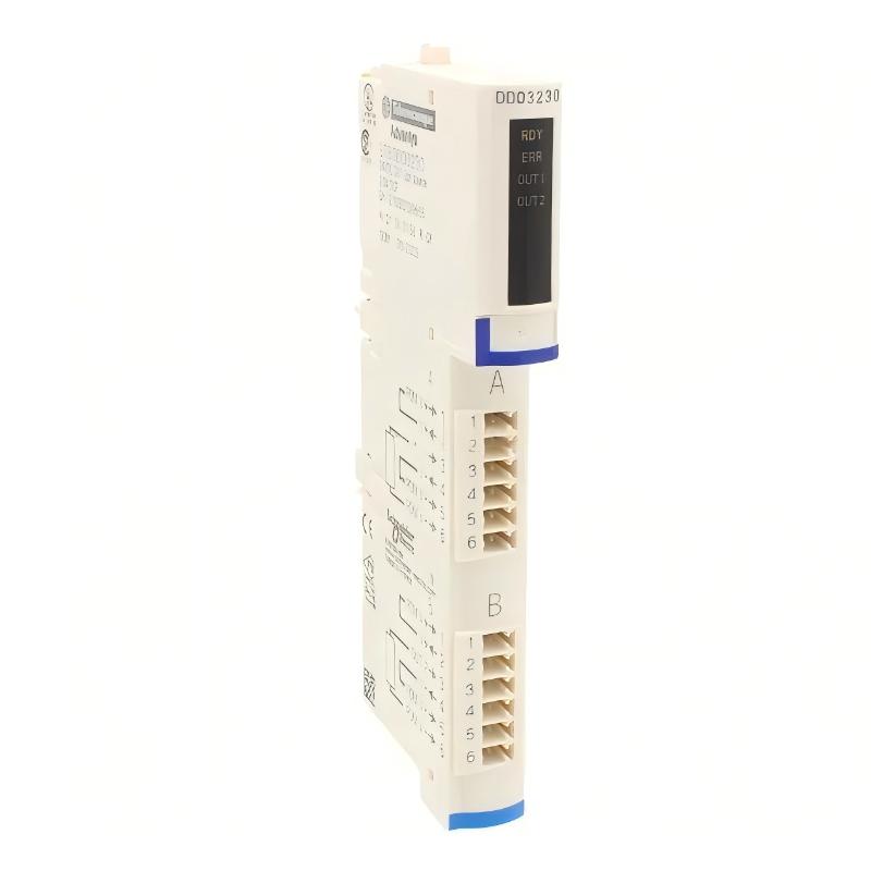
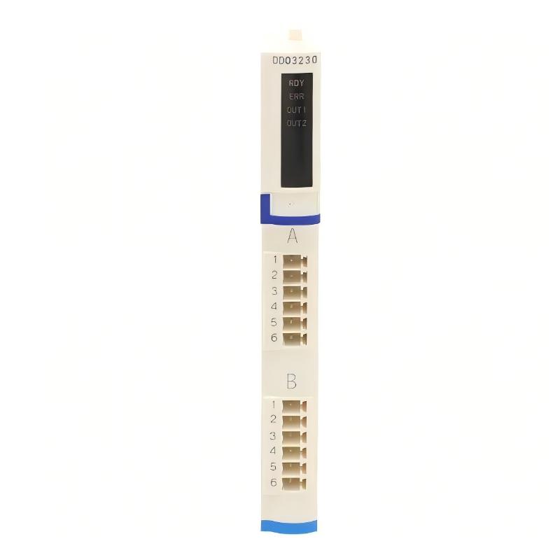
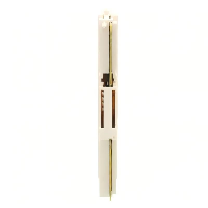
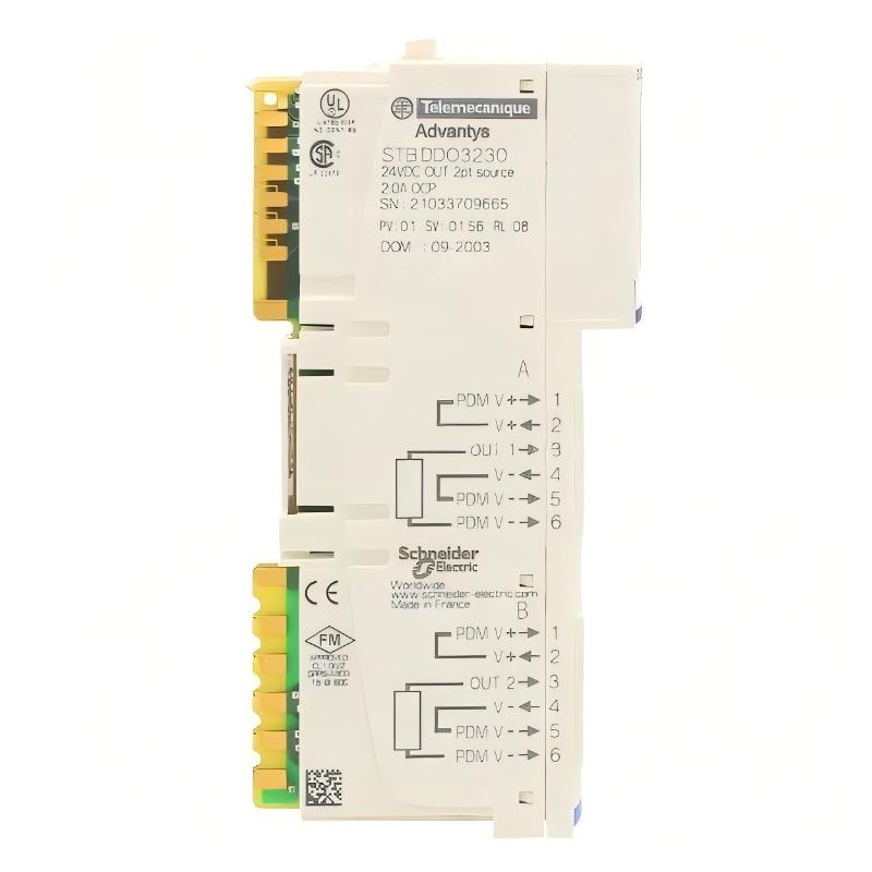
- Schneider
- STBDDO3230K
- Standard Digital Output Kit
- France
- 128.3 x 13.9 x 70 mm
- 0.116 kg
- Xiamen, China
- New & In Stock
- T/T, PayPal, Western Union
- 1 Year
- 1-3 Working Days
- DHL, UPS, TNT, FedEx and EMS.
- 24-Hour Service
- COO
- 4
Our advantage

Global Logistics
We have a 10-year logistics and express cooperation agreement, so our products can be shipped to any place in the world.

Brand new and original
Our products are imported in bulk from the place of origin. Because of the cooperative relationship, our products are all original and 100% new.

24-hour service
We provide 7*24 hours service to our customers. We will be there whenever you need us.

Price advantage
All our products are priced very favorably because we have our own warehouse and supply.
| Company Information | |||
| [email protected] | |||
| Mobile | +8615980777398 | ||
| +8615980777398 | |||
| 15980777398 |
Product Overview
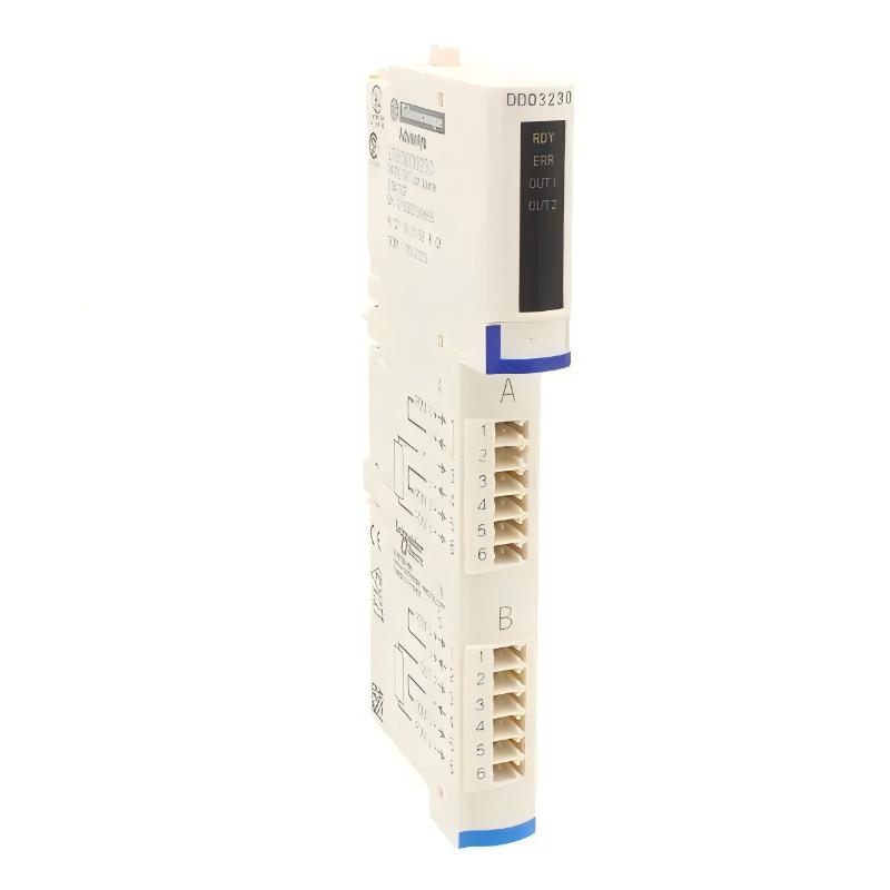
The Schneider Electric STBDDO3230K Standard Digital Output Kit is a digital output solution designed for the Modicon STB distributed I/O system. It enables a programmable logic controller (PLC) to switch compatible 24 V DC field devices according to control logic, machine status, and process requirements.
Digital output modules are important components in industrial automation because they translate controller commands into electrical signals for field equipment. These signals can operate compatible solenoid valves, interface relays, contactors, indicator lamps, and other devices that accept suitable 24 V DC control signals.
The STBDDO3230K provides two solid-state digital output channels, each rated at 2 A. Its output logic can support positive or negative logic arrangements, subject to the system wiring and application configuration. The module is designed for use with the Modicon STB distributed I/O architecture, where I/O modules connect to a common base and exchange signals through the system’s logic bus.
Unlike a standalone output module, the STBDDO3230K is supplied as a kit. Its documented composition includes the STBDDO3230 output module, an STBXBA1000 I/O base, an STBXTS2100 six-terminal spring-clamp connector, and an STBXTS1100 six-terminal screw-type connector. This combination provides the primary components required to install the output module in a compatible STB I/O segment.
The kit is intended for applications requiring reliable discrete control rather than analog signal processing. It does not provide variable voltage or continuous analog output signals. Instead, each channel switches between defined output states to control compatible field devices.
The model is particularly relevant to existing Modicon STB installations that require replacement modules, maintenance stock, or additional digital output capacity. Before purchasing, users should verify the full part number, included components, output load requirements, and compatibility with the installed network interface and power-distribution modules.
Technical Specifications
| Parameter | Specification |
|---|---|
| Brand | Schneider Electric |
| Product Model | STBDDO3230K |
| Product Series | Modicon STB |
| Product Type | Standard Digital Output Kit |
| I/O Type | Digital Output |
| Number of Outputs | 2 |
| Output Type | Solid-state |
| Rated Output Voltage | 24 V DC |
| Output Voltage Range | 19.2–30 V DC |
| Rated Output Current | 2 A per channel |
| Output Logic | Positive or negative |
| Kit Composition | STBDDO3230 module, STBXBA1000 base, STBXTS2100 spring-clamp connector, STBXTS1100 screw-type connector |
| Logic Bus Consumption | 45 mA at 5 V DC |
| Protection Features | Short-circuit, thermal overload, and reverse-polarity protection |
| Status Indicators | Module status, channel status, and module error LEDs |
| Dimensions Provided | 128.3 × 13.9 × 70 mm |
| Weight Provided | 0.116 kg |
| Product Lifecycle | Scheduled for discontinuation |
| Typical Application | PLC-controlled 24 V DC field devices |
Note: The 2 A output rating applies to each channel within the module’s operating limits. Actual load suitability depends on the load type, wiring, power supply, ambient temperature, and applicable installation requirements.
Function and Working Principle
The STBDDO3230K operates as an output interface between a PLC-based control system and connected field devices. When the controller issues an output command, the module changes the electrical state of the relevant output channel.
1. Digital Signal Switching
A digital output represents a discrete state, commonly ON or OFF. The PLC program determines when a channel should change state based on sensor inputs, process conditions, timers, interlocks, and control sequences.
For example, when a machine reaches a specified operating condition, the PLC can activate an output to energize a compatible solenoid valve. When the required condition is no longer present, the PLC can switch the output off.
The STBDDO3230K uses solid-state switching rather than mechanical relay contacts. This design is suitable for compatible DC loads requiring electronic switching. The load current and switching frequency must remain within the manufacturer’s limits.
2. Two-Channel Output Control
The module provides two digital output channels. Each channel can control an appropriate field device, provided the device’s voltage, current, and electrical characteristics are compatible with the output.
Typical examples include two small actuators, a pair of indicator devices, or separate interface relays. The number of devices that can be controlled depends on their electrical requirements and the wiring arrangement.
A two-channel design can also be useful when a machine requires a small number of discrete outputs in a compact distributed I/O segment.
3. Positive and Negative Output Logic
The documented output logic supports positive or negative logic arrangements. The actual implementation depends on the field power supply, wiring topology, load connections, and control-system design.
Positive and negative logic describe how the electrical state corresponds to the commanded ON or OFF state. They should not be confused with the controller’s software naming conventions.
Engineers should follow the module’s wiring diagrams and verify the electrical reference points before connecting field devices.
4. Output Protection
The STBDDO3230K specification includes short-circuit protection, thermal overload protection, and reverse-polarity protection. These features help protect the module under defined fault conditions.
The product documentation also specifies an external time-lag fuse rated at 2.5 A for each output. Appropriate external protection remains important even when electronic protection is available.
Protection features do not eliminate the need to calculate load current, choose suitable conductors, and follow the manufacturer’s installation instructions.
5. Status Monitoring
The module includes indicators for overall module status, individual output-channel status, and module errors. These indicators help maintenance personnel determine whether the module is operating normally and whether an output channel has been commanded or has encountered a fault condition.
LED indications should be interpreted alongside PLC diagnostics, field-device status, and electrical measurements. A channel indicator alone does not prove that the connected actuator is functioning correctly.
Role in Industrial Control Systems
The STBDDO3230K is designed for the Modicon STB distributed I/O architecture. Distributed I/O places input and output modules closer to field devices, reducing the need to route every field signal directly to a central control cabinet.
PLC Output Interface
The PLC executes control logic and determines when the connected field devices should operate. The digital output module provides the electrical interface between the controller’s commands and compatible field loads.
For example, a PLC can use sensor information to determine when a conveyor gate should open or when a valve should change state. The STBDDO3230K then switches the corresponding output channel.
Distributed I/O Architecture
The Modicon STB system allows different I/O modules to be assembled into a distributed segment. A compatible network interface module manages communication with the higher-level controller, while the I/O modules perform their assigned signal functions.
The STBDDO3230K uses the STBXBA1000 base included in the kit. The complete I/O segment also requires a compatible network interface and suitable power-distribution arrangements.
System compatibility should be confirmed before adding or replacing a module, particularly where the installation uses an established network configuration or legacy PLC hardware.
Field Device Coordination
Digital outputs can control devices such as solenoid valves, interface relays, and compatible indicator equipment. The PLC coordinates these outputs with inputs, alarms, timers, and machine sequences.
In a packaging machine, for example, one output might operate an actuator while another controls an indicator or a compatible interface device. The actual allocation depends on the control program and electrical design.
System Diagnostics and Maintenance
Output status indicators and PLC diagnostics help technicians investigate problems such as missing field power, incorrect wiring, overloaded channels, and defective actuators.
For effective troubleshooting, technicians should examine the complete signal path, from the PLC command and network communication through the output channel, field wiring, and connected device.
Industrial Applications
The STBDDO3230K is intended for discrete control in industrial automation systems that use compatible 24 V DC field devices.
1. Solenoid Valve Control
Solenoid valves are commonly used to direct compressed air, hydraulic fluid, or other process media. A compatible digital output can switch a solenoid valve or its interface circuit in response to PLC commands.
Before connecting a valve directly, verify its rated current, inrush characteristics, inductive load requirements, and any necessary suppression components.
2. Conveyor and Material-Handling Systems
Conveyor systems often use digital outputs to operate gates, diverters, stops, and other auxiliary devices. The PLC can coordinate these actions with photoelectric sensors, position switches, and downstream equipment.
The two output channels can serve two suitable control functions, provided the loads remain within the module’s electrical ratings.
3. Packaging Machinery
Packaging equipment uses discrete outputs to control actuators, pneumatic valves, indicators, and other devices that perform specific machine operations.
The STBDDO3230K can form part of a distributed I/O segment that allows the controller to coordinate these devices with product detection, timing, and sequence logic.
4. Assembly and Manufacturing Equipment
Assembly machinery frequently requires discrete commands for clamps, stops, ejectors, and auxiliary mechanisms. A digital output module provides a means of issuing these commands through PLC logic.
Where the application involves hazardous motion or safety-critical functions, the standard output module must not be treated as a safety-rated output. Appropriate safety equipment and safety logic are required for the application.
5. Process Automation
Industrial process systems may use discrete outputs to operate small valves, alarms, and auxiliary devices. The module can support these functions when the connected equipment uses compatible 24 V DC signals.
Applications involving hazardous areas, high-energy loads, or specialized electrical requirements need additional engineering assessment before installation.
6. Machine Status and Indication
Compatible signal lamps and indicator devices can be controlled by PLC output logic to communicate machine states. Examples include operation indicators, fault annunciation, and status signaling.
The load current and electrical interface must be verified before connecting an indicator directly to the module.
Installation and System Integration
Correct installation is essential for reliable output switching and protection of the module and connected equipment.
1. Verify the Complete Kit
The STBDDO3230K is a kit rather than only the output electronics. Confirm that the shipment includes the STBDDO3230 module, STBXBA1000 base, STBXTS2100 spring-clamp connector, and STBXTS1100 screw-type connector.
If the kit is being used to replace an installed module, compare the part number and connector arrangement with the existing assembly.
2. Install the I/O Base
Mount the STBXBA1000 base in the compatible Modicon STB I/O segment according to the system installation instructions. Check that the base is correctly secured and aligned with adjacent modules.
Allow adequate space for wiring access, maintenance, and the environmental conditions specified for the complete assembly.
3. Connect the Power Distribution System
The module uses a 24 V DC field-output arrangement and receives its logic power through the STB system’s logic bus. The field supply and logic supply have different functions and should be wired according to the system design.
Use a compatible power distribution module, such as the appropriate STBPDT3100 or STBPDT3105 configuration, as specified for the installation. Confirm the exact variant and wiring arrangement before energizing the system.
4. Wire the Output Channels
Connect each output channel to the intended field device using the manufacturer’s wiring diagram. Check output polarity, field-power connections, return conductors, load current, and protective fusing.
The kit includes both spring-clamp and screw-type connectors. Use the appropriate connector for the installation and ensure that the conductors are securely terminated.
For inductive loads such as solenoid coils and relay coils, verify whether suitable suppression is required. Incorrectly handled inductive energy can affect switching performance and equipment reliability.
5. Configure the PLC and Distributed I/O
Verify that the PLC project, network interface module, and I/O configuration correctly identify the installed output module. Confirm the output addresses and ensure that each PLC command corresponds to the intended physical channel.
If the module is being added to an existing system, follow the applicable configuration and commissioning procedure. Do not assume that a replacement or newly installed module will automatically be recognized in every network configuration.
6. Test the Field Devices
After installation, verify the supply voltage, inspect wiring, and test each output channel under controlled conditions.
Confirm that the PLC command, module indicator, field voltage, and device response agree. Check the output behavior during startup, normal operation, and fault conditions.
Document the channel assignments and wiring so that future maintenance personnel can identify the connected field devices quickly.
Compatible System Components
The STBDDO3230K is designed to operate within a compatible Modicon STB distributed I/O segment. The following components may be used in the wider system, depending on the application.
| Component | Function | Compatibility Considerations |
|---|---|---|
| STBDDO3230 output module | Provides two 24 V DC digital outputs | Included in the kit |
| STBXBA1000 I/O base | Provides the module mounting and connection base | Included in the kit |
| STBXTS2100 connector | Six-terminal spring-clamp connection | Included in the kit |
| STBXTS1100 connector | Six-terminal screw-type connection | Included in the kit |
| Modicon STB network interface module | Connects the distributed I/O segment to the control network | Select a variant compatible with the PLC and network |
| STBPDT3100 or STBPDT3105 power distribution module | Distributes field power within the I/O segment | Confirm the exact system and wiring requirements |
| 24 V DC power supply | Supplies compatible field devices | Size according to total load current and system requirements |
| PLC or PAC | Executes machine-control logic | Verify supported network and I/O configuration |
| Solenoid valve | Performs fluid or pneumatic switching | Check voltage, current, inrush, and suppression requirements |
| Interface relay | Isolates or adapts a control signal for another load | Confirm coil current and contact ratings |
| Indicator lamp | Displays machine or process status | Verify 24 V DC compatibility and load current |
Not every component is included in the STBDDO3230K package. Check the bill of materials for the actual installation before ordering additional parts.
Alternative Models and Replacement Considerations
Schneider Electric identifies the Modicon Edge I/O NTS NTSDDO0802K as a replacement for the STBDDO3230K. However, the replacement is an eight-output module with a different product architecture, so it should not be assumed to be a direct plug-in replacement.
| Model or Option | Description | Replacement Considerations |
|---|---|---|
| STBDDO3230K | Original two-channel, 24 V DC standard digital output kit | Maintains the original STB configuration when the kit is compatible |
| STBDDO3230 | Output module supplied as part of the original kit | Check whether the base and connectors are already available and suitable |
| NTSDDO0802K | Modicon Edge I/O NTS digital output module and base | Verify network architecture, configuration, wiring, dimensions, and output requirements |
| Other Modicon STB output modules | Alternative output modules within the STB family | Output count, current rating, switching type, and connectors may differ |
Before selecting an alternative, compare:
- Output voltage and maximum channel current.
- Number of output channels.
- Solid-state or relay switching type.
- Positive or negative logic requirements.
- Field-power distribution and wiring.
- Base and connector compatibility.
- PLC and network interface support.
- I/O addressing and configuration requirements.
- Electrical protection and load characteristics.
- Mounting dimensions and available cabinet space.
A module with a similar appearance or voltage rating may not provide the same output behavior. Replacing the original STB kit with a different I/O family may require system redesign, configuration changes, and commissioning.
Key Advantages
Compact Two-Channel Design
The two-channel configuration provides digital output capacity for applications with a limited number of field devices. Its compact dimensions can help make efficient use of distributed I/O cabinet space.
Solid-State Switching
Solid-state outputs provide electronic switching for compatible DC loads without relying on mechanical relay contacts. Load compatibility and switching limits must still be observed.
24 V DC Industrial Control
The module is designed for common 24 V DC control applications, including compatible solenoid valves, interface devices, and indicator equipment.
Integrated Protection Features
The specified protection functions include short-circuit, thermal overload, and reverse-polarity protection. These features support reliable operation when the module is installed and used within its documented limits.
Status Indicators
Module, output-channel, and error indicators help technicians identify operating conditions and support troubleshooting.
Complete Kit Configuration
The STBDDO3230K includes the output module, I/O base, and two types of terminal connectors. This simplifies component identification for applications that require the complete kit.
Compatibility with Modicon STB Systems
The kit is intended for the Modicon STB distributed I/O architecture, making it relevant to existing installations that use compatible STB bases, network interfaces, and power distribution.
Technical FAQs
1. What is the Schneider Electric STBDDO3230K?
The STBDDO3230K is a standard digital output kit for the Modicon STB distributed I/O system. It provides two solid-state digital outputs for compatible 24 V DC field devices.
2. How many output channels does it provide?
It provides two digital output channels, each rated at up to 2 A within the manufacturer’s operating conditions.
3. What is the rated output voltage?
The module is designed for 24 V DC output operation. Its specified operating output voltage range is 19.2–30 V DC.
4. What components are included in the kit?
The documented kit composition includes the STBDDO3230 output module, STBXBA1000 base, STBXTS2100 six-terminal spring-clamp connector, and STBXTS1100 six-terminal screw-type connector.
5. Can it control solenoid valves?
Yes, it can control compatible 24 V DC solenoid valves or their interface circuits, provided that the electrical load, inrush current, and inductive switching requirements are within the permitted limits.
6. Does it use relay contacts?
No. The STBDDO3230 uses solid-state outputs rather than mechanical relay contacts.
7. What protection functions are provided?
The product specifications identify short-circuit protection, thermal overload protection, and reverse-polarity protection. The installation also requires the specified external output fusing and suitable wiring protection.
8. Can it be installed in any PLC system?
No. It is designed for the Modicon STB distributed I/O architecture. The network interface, I/O base, power-distribution arrangement, and controller configuration must be compatible.
9. Is the STBDDO3230K being discontinued?
Schneider Electric lists December 1, 2027, as the planned discontinuation date for commercialization and December 31, 2035, as the end-of-service date on its US product page. Availability and service dates can vary by region, so verify the applicable local product information before purchasing.
10. What is the recommended replacement?
Schneider Electric lists NTSDDO0802K from the Modicon Edge I/O NTS family as a replacement. Because it has a different channel count and system architecture, compatibility and integration requirements must be evaluated before substitution.
Procurement and Maintenance Recommendations
When purchasing the STBDDO3230K, confirm that the full catalog number matches the required application. Since the kit includes a base and two connector types, verify whether the order is for the complete kit or only the output module.
For replacement projects, compare the existing module’s output voltage, current requirements, logic configuration, connector arrangement, and network architecture. Confirm the installed STB network interface and power-distribution module before adding the kit to an existing segment.
For used or surplus units, inspect the housing, terminals, connector condition, and visible signs of overheating or contamination. Where practical, obtain functional test information and confirm the seller’s warranty and return terms.
During maintenance, check field wiring, terminal tightness, supply voltage, protective fuses, and connected loads. If an output fails to operate, verify the PLC command, network status, module indicators, field supply, wiring, and actuator condition before replacing the module.
Because Schneider Electric has announced a planned discontinuation date, maintenance teams should review future spare-parts requirements and evaluate the recommended replacement where appropriate. Any migration to a different I/O platform should include a compatibility assessment, updated wiring documentation, and a controlled commissioning procedure.
Conclusion
The Schneider Electric STBDDO3230K Standard Digital Output Kit is a two-channel, 24 V DC solid-state output solution for compatible Modicon STB distributed I/O systems. With a rated output current of 2 A per channel, built-in diagnostic indicators, and documented protection features, it supports the control of suitable industrial field devices.
The kit includes the STBDDO3230 module, STBXBA1000 base, and spring-clamp and screw-type terminal connectors. For reliable operation, users should verify electrical load requirements, power distribution, wiring, and controller compatibility before installation.
As the product approaches its planned discontinuation date, industrial users should confirm availability and assess the recommended NTSDDO0802K replacement when planning long-term maintenance or system upgrades.