

ProductPRODUCT
Featured products
Contact Us
- Schneider
- STBACI1400K
- Standard Analog Input Kit
- France
- 70 × 18.4 × 128.3 mm
- 0.147 kg
- Xiamen, China
- New & In Stock
- T/T, PayPal, Western Union
- 1 Year
- 1-3 Working Days
- DHL, UPS, TNT, FedEx and EMS.
- 24-Hour Service
- COO
- 6
Our advantage

Global Logistics
We have a 10-year logistics and express cooperation agreement, so our products can be shipped to any place in the world.

Brand new and original
Our products are imported in bulk from the place of origin. Because of the cooperative relationship, our products are all original and 100% new.

24-hour service
We provide 7*24 hours service to our customers. We will be there whenever you need us.

Price advantage
All our products are priced very favorably because we have our own warehouse and supply.
| Company Information | |||
| [email protected] | |||
| Mobile | +8615980777398 | ||
| +8615980777398 | |||
| 15980777398 |
Product Overview
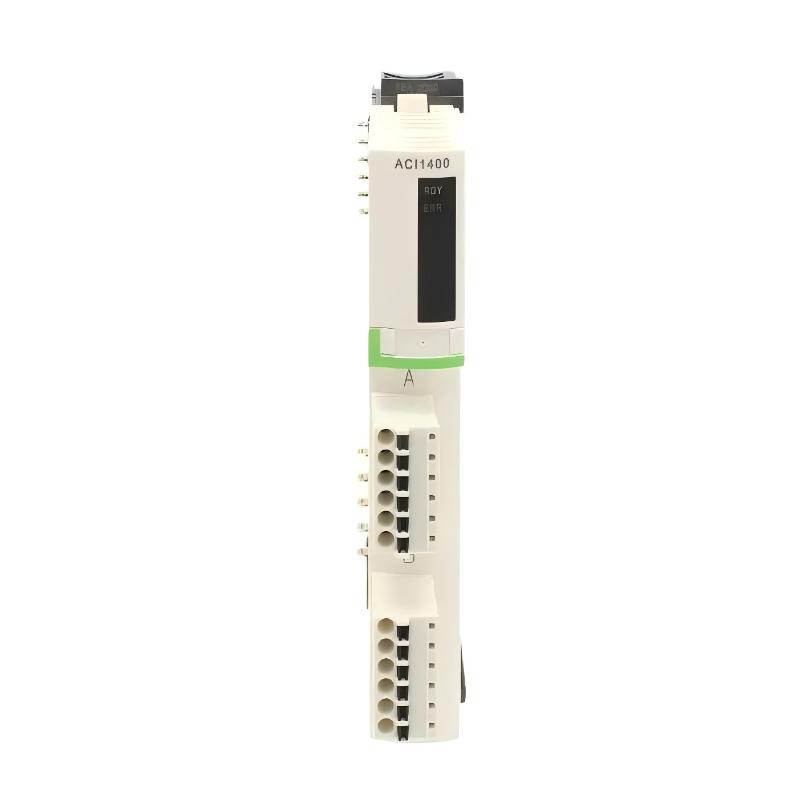
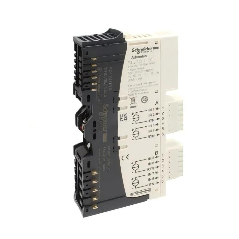
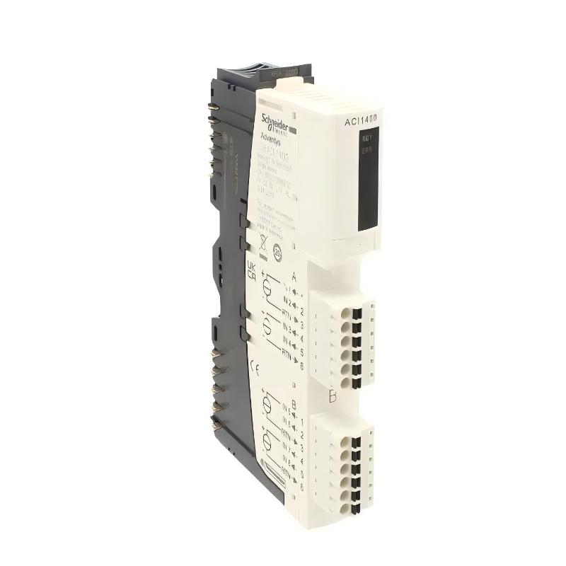
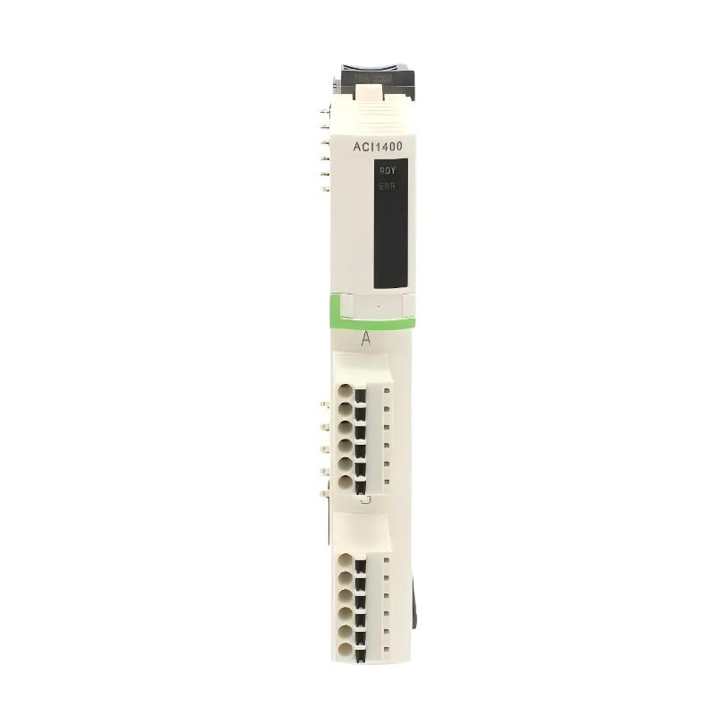
The Schneider STBACI1400K is a Modicon STB Standard Analog Input Kit for bringing continuous current signals from field instruments into a distributed I/O system. It is intended for applications where transmitters such as pressure, flow, level, or other process sensors use standard 4–20 mA or 0–20 mA outputs.
The kit contains the analog input module together with the associated mounting and connection hardware, making it useful when an entire STB analog input position needs to be installed or replaced rather than replacing the electronic module alone.
In a water treatment system, for example, several transmitters can be connected to the eight analog input channels to monitor pump discharge pressure, tank level, or flow. In a machine-control panel, the same type of input can collect continuous feedback from process instruments and pass the values to the controller for monitoring and control logic.
The STBACI1400K belongs to the modular Modicon STB distributed I/O platform. An STB island can be located near the field devices while its network interface connects the collected I/O data to the PLC or PAC. This arrangement can reduce the amount of individual field wiring that needs to run back to a central controller cabinet.
For replacement work, the complete kit reference should be checked along with the installed STB island configuration, network interface, terminal arrangement, field signal type, and controller configuration.
Technical Specifications
| Parameter | Specification |
|---|---|
| Manufacturer | Schneider Electric |
| Model | STBACI1400K |
| Product Family | Modicon STB |
| Product Type | Standard Analog Input Kit |
| Analog Input Type | Current |
| Number of Inputs | 8 |
| Input Signal | 0–20 mA / 4–20 mA |
| Resolution | 15 bits + sign |
| Rated Supply Voltage | 24 V DC |
| Logic Bus Current Consumption | 90 mA at 5 V DC |
| Update Time | 22 ms |
| Protection Degree | IP20 |
| Hot Swapping | Yes, with standard NIM |
| Module Type | Standard Analog Input |
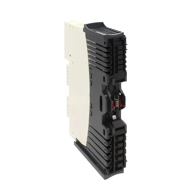
| Kit Components | STBACI1400 module, STBXBA2000 base, STBXTS1100 screw connector, STBXTS2100 spring-clamp connector |
| Compatible Power Distribution Modules | STBPDT3100 / STBPDT3105 |
| Dimensions | 70 × 18.4 × 128.3 mm |
| Weight | 0.147 kg |
Product Features
- Modicon STB Standard Analog Input Kit
- Model STBACI1400K
- Eight analog current input channels
- Supports 0–20 mA and 4–20 mA signals
- 15-bit + sign resolution
- 24 V DC supply
- 22 ms input update time
- Modular installation within a Modicon STB island
- Suitable for process transmitters and analog instrumentation
- Supports distributed field signal acquisition
- Kit includes the associated mounting base and terminal connectors
- Compatible with STB power distribution arrangements
- Suitable for PLC and PAC-based automation systems
- Supports applications requiring continuous analog measurement rather than simple discrete status signals
Working Principle
The STBACI1400K sits between field transmitters and the controller’s I/O data structure.
4–20 mA Transmitter → STBACI1400K → STB Island → Network Interface → PLC / PAC
A field transmitter sends a current signal corresponding to the measured process variable. The analog input channel receives that signal and converts it into a digital value that the STB system can pass to the controller.
For a typical 4–20 mA loop, the controller application interprets the lower and upper current levels according to the transmitter’s configured measuring range. A pressure transmitter, for example, may use the current loop to represent a defined pressure range. The PLC program can then use that value for display, alarm handling, interlocks, calculations, or process control.
The module handles the field-side analog acquisition. The STB network interface and island architecture handle communication between the distributed I/O assembly and the controller.
This separation is useful in installations where instruments are located around a machine or process area. The analog signals can terminate at the nearby STB island instead of requiring every transmitter cable to return individually to the main PLC cabinet.
Role in a Modicon STB Distributed I/O Control Architecture
The STBACI1400K occupies the analog signal acquisition position within a Modicon STB distributed I/O island.
Field Instruments → STBACI1400K → STB Island Bus → NIM → Industrial Network → PLC / PAC
| System Element | Function |
|---|---|
| STBACI1400K | Acquires 0–20 mA and 4–20 mA analog signals |
| STBACI1400 | Analog input module included in the kit |
| STBXBA2000 | Mounting base for the STB module |
| STBXTS1100 | Screw-type field connection |
| STBXTS2100 | Spring-clamp field connection |
| STBPDT3100 / STBPDT3105 | Distributes power within the STB island |
| Network Interface Module | Connects the STB island with the controller network |
| PLC / PAC | Processes the acquired analog values |
| Field Transmitter | Generates the analog measurement signal |
The actual island configuration depends on the selected network interface, power distribution arrangement, I/O modules, and application requirements.
Industrial Applications
| Application | Typical Use |
|---|---|
| Water Treatment | Acquiring pressure, flow, and level transmitter signals |
| Pump Control | Monitoring discharge pressure, suction pressure, and flow |
| Process Automation | Bringing continuous process measurements into the PLC |
| HVAC Systems | Monitoring pressure and other analog operating variables |
| Packaging Machinery | Acquiring analog feedback from machine instrumentation |
| Food and Beverage Equipment | Monitoring process conditions through analog transmitters |
| Chemical Processing | Collecting continuous measurements from field instruments |
| Material Handling | Monitoring analog feedback associated with equipment operation |
| Manufacturing Lines | Connecting distributed process sensors to the control system |
| Utility Equipment | Centralizing analog measurements at distributed STB I/O stations |
Installation and Maintenance
- Confirm the complete STBACI1400K reference before installation or replacement.
- Verify that the connected field instruments use compatible 0–20 mA or 4–20 mA signals.
- Check the number of analog channels required by the application.
- Confirm the existing Modicon STB island and network interface configuration.
- Verify the mounting base and terminal components supplied with the kit.
- Check the 24 V DC control and I/O power arrangement before energizing the system.
- Inspect transmitter wiring for loose terminals, damaged conductors, and incorrect polarity.
- Confirm the analog channel assignments in the PLC or PAC application.
- Check the configured engineering range for each connected transmitter.
- Compare the displayed process values with the expected field measurements during commissioning.
- If an input remains abnormal, check the transmitter, current loop, terminal connection, power supply, and software configuration before replacing the module.
- Record the final channel-to-instrument mapping so future maintenance work can identify each analog input without tracing the entire field installation.
For a suspected 4–20 mA problem, measuring the current in the field loop can help determine whether the problem originates from the transmitter and wiring or from the I/O and controller side.
Related Components
| Component | Function |
|---|---|
| STBACI1400 | Standard eight-channel analog input module |
| STBXBA2000 | Mounting base for the analog input module |
| STBXTS1100 | Screw-type terminal connector |
| STBXTS2100 | Spring-clamp terminal connector |
| STBPDT3100 | STB power distribution module |
| STBPDT3105 | STB power distribution module |
| Standard NIM | Network interface for the STB island |
| 24 V DC Power Supply | Supplies control and I/O power |
| 4–20 mA Transmitter | Generates process measurement signals |
| PLC / PAC | Processes analog input information |
Recommended Related Models
| Model / Product Family | Product Type | Typical Application |
|---|---|---|
| Schneider STBACI1400 | Standard Analog Input Module | Eight-channel current signal acquisition |
| Schneider STBACI0320K | Standard Analog Input Kit | Analog current input applications with fewer channels |
| Schneider STBAVI1400K | Standard Analog Input Kit | Voltage-based analog signal acquisition |
| Schneider STBXBA2000 | Mounting Base | Installation of STB I/O modules |
| Schneider STBPDT3100 | Power Distribution Module | STB island power distribution |
| Schneider STBPDT3105 | Power Distribution Module | Alternative STB power distribution arrangement |
| Schneider Modicon STB | Distributed I/O Platform | Modular machine and process I/O |
Key Advantages
- Eight analog current inputs in one STB I/O position.
- Supports standard 4–20 mA and 0–20 mA instrumentation signals.
- 15-bit plus sign resolution.
- Suitable for distributed process instrumentation.
- Kit includes the associated base and terminal hardware.
- Integrates with the modular Modicon STB architecture.
- Suitable for PLC and PAC-based control systems.
- Useful for pressure, flow, level, and similar continuous measurements.
Technical FAQs
How many transmitters can the STBACI1400K connect to?
The STBACI1400K has eight analog input channels, allowing up to eight compatible analog current signals to be acquired through the module under the appropriate system configuration.
Can the STBACI1400K handle both 4–20 mA and 0–20 mA signals?
Yes. The module supports both 4–20 mA and 0–20 mA input ranges. The selected signal range should correspond to the connected transmitter and the configuration used by the controller application.
What is the difference between STBACI1400 and STBACI1400K?
The STBACI1400 refers to the analog input module itself, while STBACI1400K is supplied as a kit that includes the module together with associated installation components such as the mounting base and terminal connectors. This distinction matters when determining the scope of a replacement order.
Why might a 4–20 mA input show an incorrect process value?
An incorrect value can result from several points in the signal path, including transmitter calibration, loop power, wiring polarity, terminal connections, channel configuration, or the engineering range configured in the PLC application. Checking the actual loop current is a useful first step when separating a field-side issue from an I/O configuration problem.