

ProductPRODUCT
Featured products
Contact Us
- Schneider
- LTMR08DBD
- Motor Controller
- France
- 91 x 61 x 122.5 mm
- 0.53 kg
- Xiamen, China
- New & In Stock
- T/T, PayPal, Western Union
- 1 Year
- 1-3 Working Days
- DHL, UPS, TNT, FedEx and EMS.
- 24-Hour Service
- COO
- 2
Our advantage

Global Logistics
We have a 10-year logistics and express cooperation agreement, so our products can be shipped to any place in the world.

Brand new and original
Our products are imported in bulk from the place of origin. Because of the cooperative relationship, our products are all original and 100% new.

24-hour service
We provide 7*24 hours service to our customers. We will be there whenever you need us.

Price advantage
All our products are priced very favorably because we have our own warehouse and supply.
| Company Information | |||
| [email protected] | |||
| Mobile | +8615980777398 | ||
| +8615980777398 | |||
| 15980777398 |
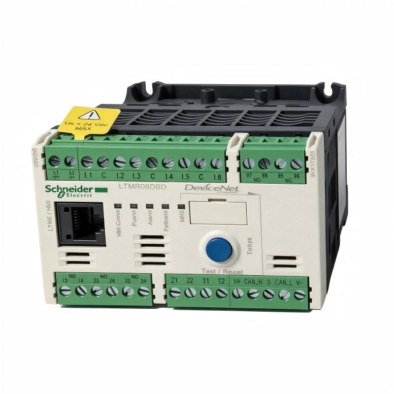
Product Overview
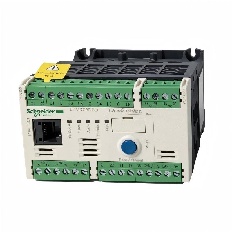
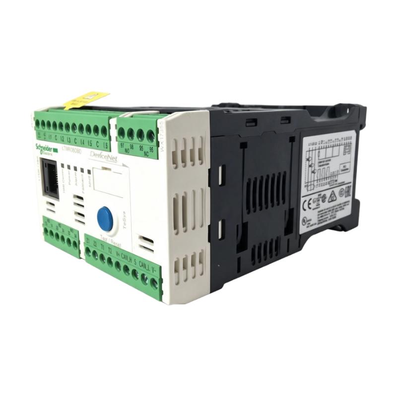
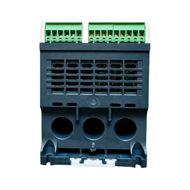
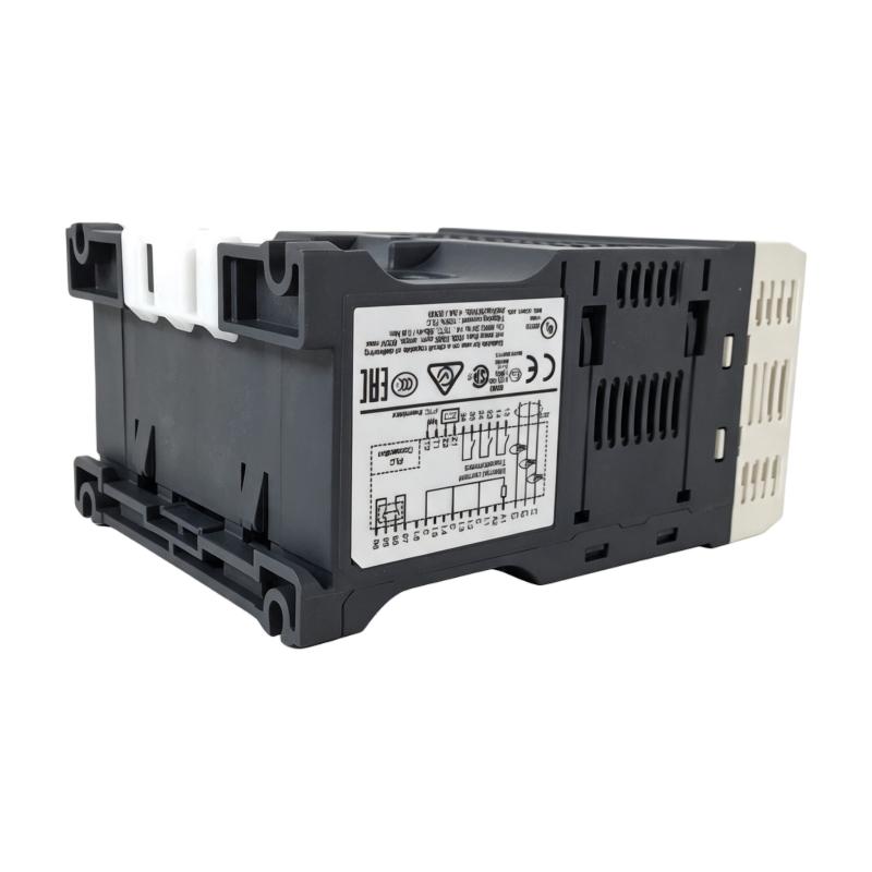
The Schneider Electric LTMR08DBD Motor Controller is an intelligent motor management controller in the TeSys T product family. It is designed to support motor protection, operational monitoring, fault detection, and control in industrial automation systems. By combining current measurement, configurable protection functions, digital inputs and outputs, and DeviceNet communication, the controller helps integrate motor management into automated production and process-control environments.
Unlike a basic motor starter, the LTMR08DBD provides motor-related operating information and configurable alarm and trip functions. It can help maintenance teams identify abnormal operating conditions, monitor motor status, and coordinate motor operation with a PLC or distributed control system.
The controller supports a motor current measurement range of 0.4–8 A and uses a 24 V DC control supply. Its communication interface is based on DeviceNet, making it suitable for compatible automation architectures that use this industrial network. The device includes six logic inputs and three relay logic outputs according to the manufacturer’s product description.
The LTMR08DBD is intended for equipment monitoring and control rather than serving as a standalone replacement for every component in a motor starter. A complete installation normally requires appropriate short-circuit protection and switching equipment, such as a correctly selected contactor. The overall system must be engineered to meet the motor’s electrical requirements and the applicable safety standards.
This model is particularly relevant to industrial facilities maintaining existing TeSys T and DeviceNet-based systems. Before purchasing a replacement, users should verify the complete model number, control supply, current range, communication protocol, terminal arrangement, and installed accessories.
Technical Specifications
| Parameter | Specification |
|---|---|
| Brand | Schneider Electric |
| Product Series | TeSys T |
| Model | LTMR08DBD |
| Product Type | Motor Management Controller |
| Primary Function | Motor protection, monitoring, and control |
| Current Measurement Range | 0.4–8 A |
| Rated Control Supply | 24 V DC |
| Control Supply Limits | 20.4–26.24 V DC |
| Typical Current Consumption | 56–127 mA |
| Communication Protocol | DeviceNet |
| Logic Inputs | 6 |
| Relay Logic Outputs | 3, as specified in the product description |
| Rated Insulation Voltage | Up to 690 V, subject to circuit and applicable standard |
| Short-Circuit Withstand Rating | Up to 100 kA under specified coordinated conditions |
| Dimensions Provided | 91 × 61 × 122.5 mm |
| Weight Provided | 0.53 kg |
| Product Family | TeSys T Motor Management System |
| Typical Application | Industrial motor protection and monitoring |
Specifications should be checked against the manufacturer’s documentation for the exact product revision and installation conditions. Short-circuit withstand ratings depend on the specified protective-device coordination and are not a standalone rating for every installation.
Function and Working Principle
The LTMR08DBD monitors electrical and operational conditions associated with a motor and applies configured protection and control logic. It receives current measurements and external signals, evaluates them against programmed parameters, and makes relevant status, alarm, or trip information available to the control system.
1. Motor Current Measurement
Motor current is an important indicator of operating load. The LTMR08DBD supports a measurement range of 0.4–8 A, allowing it to be configured for compatible motor applications within that range.
Current monitoring helps the controller identify conditions such as overload, excessive starting current, or abnormal load behavior. Correct configuration depends on the motor nameplate data and the actual application.
The controller should not be selected solely because the motor’s nominal current falls somewhere within the measurement range. Starting characteristics, duty cycle, protection settings, and the overall starter arrangement must also be considered.
2. Motor Protection
The TeSys T system provides configurable protection functions for supported motor applications. Depending on the selected settings and installation, these can include thermal overload protection, phase-related protection, locked-rotor detection, and other electrical fault monitoring.
Protection parameters must be selected to match the motor and its operating conditions. Incorrect settings may cause nuisance trips or fail to provide the intended level of protection.
The controller should be used with the required short-circuit protective devices and switching equipment. It does not eliminate the need for a properly engineered motor starter.
3. Digital Input Monitoring
The LTMR08DBD includes six logic inputs. These inputs can be used in the control scheme to receive supported external signals, depending on the wiring and application configuration.
For example, a motor-control system may use external signals to represent operating commands, equipment interlocks, or status conditions. The exact function of each input depends on the system design and configured logic.
Input wiring must follow the manufacturer’s terminal and electrical requirements. Engineers should verify signal voltage, common references, and the intended function before commissioning.
4. Relay Output Control
The controller provides three relay logic outputs as specified in the product description. These outputs can support configured control and signaling functions within the motor-management system.
They may be used to communicate operational states or interact with external control circuits, subject to the relay ratings and application design. They should not be assumed to switch a motor’s main power circuit directly.
The output assignment, contact ratings, and required external interface equipment must be verified before wiring.
5. DeviceNet Communication
The LTMR08DBD uses DeviceNet to communicate with compatible automation equipment. DeviceNet allows motor-related status, diagnostics, and supported control information to be exchanged with a networked controller.
This can reduce the need for separate hardwired signals for every monitoring function and provide more detailed information for maintenance and troubleshooting.
The communication configuration must match the network’s addressing, data rate, cabling, termination, and master or scanner configuration. A DeviceNet model is not interchangeable with a Modbus, CANopen, PROFIBUS, or Ethernet model without a broader system-level evaluation.
Role in Industrial Control Systems
The LTMR08DBD is designed to operate as part of a coordinated motor-management system. It can exchange information with a PLC or other compatible automation controller while monitoring motor-related electrical conditions.
PLC Integration
A PLC can use motor status and fault information to coordinate machinery, manage production sequences, and respond to abnormal operating conditions. With DeviceNet communication, the LTMR08DBD can exchange supported data with a compatible DeviceNet scanner or controller.
Integration requires correct network configuration, suitable device data mapping, and appropriate PLC logic. The PLC program should account for startup conditions, communication faults, trip states, and reset requirements.
Motor Starter Coordination
The LTMR08DBD works within a motor starter arrangement that includes suitable switching and short-circuit protection. The contactor provides the required switching function, while the controller provides motor management, monitoring, and configured protection functions.
The components must be selected and coordinated according to the motor rating, prospective fault current, installation conditions, and applicable electrical standards.
HMI and Operator Monitoring
A human-machine interface can display motor status, alarm information, and relevant operating data through the PLC or another supported control architecture.
This helps operators identify abnormal conditions without relying exclusively on local indicators. Alarm descriptions and reset procedures should be documented clearly so that faults are handled consistently.
Maintenance and Diagnostics
Motor-related events, trip information, and operating data can help maintenance teams investigate recurring problems. When interpreted alongside process conditions and inspection results, this information can support better maintenance planning.
However, the controller’s data should be treated as one source of diagnostic evidence. Mechanical problems, poor connections, supply issues, and process-related overloads may require additional investigation.
Industrial Applications
The LTMR08DBD is suitable for appropriately engineered motor-management applications where its current range, 24 V DC control supply, and DeviceNet communication meet the system requirements.
1. Conveyor Systems
Conveyors often operate as part of a larger production line and may require coordinated motor protection and status monitoring. The LTMR08DBD can help monitor a compatible conveyor motor and communicate relevant operating conditions to the control system.
For conveyors with frequent starts, changing loads, or potential jams, protection settings must be selected carefully. The controller should be integrated with appropriate mechanical and electrical interlocks.
2. Pumps and Fluid Handling Equipment
Industrial pumps can experience abnormal conditions caused by overload, mechanical blockage, phase problems, or changes in process demand. Motor management can help detect supported electrical fault conditions and provide useful information to operators.
The controller does not directly measure every process variable. Pressure, flow, liquid level, and other process measurements generally require separate instruments and appropriate control logic.
3. Fans and Ventilation Systems
Fans and ventilation equipment may operate for long periods, making reliable motor protection and status monitoring important. The LTMR08DBD can be considered for compatible motors within its current measurement range.
Engineers should evaluate operating duty, starting current, environmental conditions, and the required fault response before choosing the controller.
4. Packaging and Material Handling
Packaging machines and material-handling systems often include multiple motors that must operate in a coordinated sequence. A networked motor-management controller can help the PLC identify faults and manage machine responses.
DeviceNet integration can be useful in legacy systems where the network is already established and supported by the installed controller architecture.
5. General Manufacturing Equipment
The LTMR08DBD can support motor management in suitable manufacturing machinery, auxiliary equipment, and industrial process systems. Its application suitability depends on the motor’s electrical characteristics and the complete starter design.
For larger motors or applications outside the 0.4–8 A range, a controller with a different current rating may be required.
Installation and System Integration
Correct installation is essential for reliable motor protection, communication, and long-term operation.
1. Verify the Motor Current Range
Before installation, confirm that the motor’s operating current and required protection settings are compatible with the 0.4–8 A measurement range.
Use the motor nameplate and application data to establish the correct settings. Consider starting behavior, operating duty, and the requirements of the driven equipment.
2. Confirm the Control Supply
The LTMR08DBD uses a 24 V DC control supply, with a specified supply range of 20.4–26.24 V DC.
Verify the power supply’s voltage and current capacity, check polarity, and ensure that the control wiring follows the manufacturer’s instructions. Avoid confusing the controller’s control-supply voltage with the motor’s power-circuit voltage.
3. Install Appropriate Protection and Switching Equipment
The controller should be installed within a correctly designed motor starter system. Select the required contactor and short-circuit protective devices based on the motor, fault level, and applicable coordination requirements.
The published short-circuit withstand value must be interpreted together with the specified upstream protective equipment. Do not assume that the controller alone provides complete short-circuit protection.
4. Configure DeviceNet
For DeviceNet integration, verify the network address, data rate, wiring, cable type, termination, and scanner configuration.
Check that the PLC’s DeviceNet configuration matches the controller and that the required input and output data are mapped correctly. Test communication-loss handling and ensure that the system enters the intended state if communication is interrupted.
5. Wire Inputs and Outputs
Connect the six logic inputs and relay outputs according to the application wiring diagram. Confirm signal assignments, electrical ratings, relay contact requirements, and any necessary interposing relays.
Label the field wiring clearly and document the input/output functions for future troubleshooting.
6. Commission the Motor Management System
Before returning equipment to service, verify the motor nameplate data, protection settings, wiring, and network configuration. Test normal operation and appropriate fault responses under controlled conditions.
Record the configured parameters and the expected behavior for alarms, trips, resets, and communication failures. This documentation helps maintenance personnel restore the intended configuration after replacement or troubleshooting.
Compatible System Components
The LTMR08DBD is one component of a complete motor-management system. The following components may be used in an appropriate installation, subject to technical verification.
| Component | Function | Compatibility Considerations |
|---|---|---|
| Three-phase AC motor | Provides mechanical output for industrial equipment | Confirm rated current, voltage, starting characteristics, and load requirements |
| Contactor | Switches motor power | Select according to motor rating, utilization category, and switching duty |
| Circuit breaker or fuses | Provides short-circuit protection | Coordinate with the motor starter and specified controller conditions |
| PLC or DeviceNet scanner | Exchanges control and status data | Must support DeviceNet and the required data mapping |
| 24 V DC power supply | Powers the controller’s control circuits | Confirm voltage range and current capacity |
| HMI | Displays motor status and alarms | Integration may be through the PLC or another supported architecture |
| DeviceNet cable | Carries network communication | Use suitable cable, topology, termination, and shielding practices |
| Motor temperature sensor | Provides additional motor thermal information where supported | Confirm sensor type and wiring requirements |
| Ground-current sensor | Supports applicable ground-fault monitoring functions | Verify compatibility and configuration |
| TeSys T expansion module | Adds supported monitoring and measurement functions | Check the exact expansion module and required connection cable |
The actual bill of materials depends on the motor starter design and the functions required by the application. Not all components listed above are supplied with the LTMR08DBD.
Alternative Models and Replacement Considerations
The LTMR08DBD belongs to the TeSys T family and uses DeviceNet with a 24 V DC control supply. Replacement selection should preserve the required current range, communication protocol, and control functions.
| Alternative Model | Key Difference or Consideration |
|---|---|
| Schneider Electric LTMR08MBD | 0.4–8 A current range and 24 V DC supply, but uses Modbus communication |
| Schneider Electric LTMR08CBD | 0.4–8 A current range and 24 V DC supply, but uses CANopen |
| Schneider Electric LTMR08PBD | 0.4–8 A current range and 24 V DC supply, but uses PROFIBUS DP |
| Schneider Electric LTMR08EBD | 0.4–8 A current range and 24 V DC supply, with Ethernet communication supporting Modbus TCP or EtherNet/IP |
| Schneider Electric LTMR27DBD | DeviceNet and 24 V DC configuration with a higher current range of approximately 1.35–27 A |
These models are related alternatives, not automatically interchangeable replacements. A different communication protocol may require network changes, PLC configuration updates, and commissioning work.
Before selecting an alternative, compare:
- Motor current and protection requirements.
- Control-supply voltage.
- Communication protocol and network architecture.
- Logic input and output requirements.
- Expansion-module compatibility.
- Terminal assignments and wiring.
- PLC program and device configuration.
- Required certifications and application standards.
- Physical mounting and available panel space.
Where the existing installation depends on DeviceNet, retaining a compatible DeviceNet controller may reduce system modifications. If the wider automation network is being upgraded, a controller using a newer communication architecture may be considered as part of a broader engineering project.
Key Advantages
Integrated Motor Management
The LTMR08DBD combines current measurement, monitoring, configurable protection, and control functions in one controller.
DeviceNet Connectivity
Its DeviceNet interface supports integration into compatible industrial networks, allowing motor status and supported diagnostic information to be exchanged with a control system.
24 V DC Control Supply
The 24 V DC control supply is compatible with many industrial control architectures that use a separate low-voltage control-power system.
Multiple Logic Inputs
Six logic inputs support external signal monitoring and configurable control schemes, subject to the device’s input requirements.
Relay Logic Outputs
The relay outputs can be used for configured signaling and control functions within the motor starter architecture.
Maintenance Diagnostics
Motor-related alarms, trips, and operating information can help technicians investigate faults and improve maintenance planning.
TeSys T System Integration
The controller can form part of a TeSys T motor-management system with suitable switching, protection, control, and optional expansion components.
Technical FAQs
1. What is the Schneider Electric LTMR08DBD?
The LTMR08DBD is a TeSys T motor management controller designed for motor monitoring, protection, and control. It uses a 24 V DC control supply and supports DeviceNet communication.
2. What is the current measurement range?
Its specified current measurement range is 0.4–8 A. The motor and starter application must be configured within the applicable ratings and protection requirements.
3. What control voltage does it require?
The rated control supply is 24 V DC, with specified supply limits of 20.4–26.24 V DC.
4. Which communication protocol does the LTMR08DBD use?
It uses DeviceNet. Confirm that the PLC, scanner, network wiring, and device configuration support DeviceNet before installation.
5. How many logic inputs and outputs does it have?
The manufacturer’s product description lists six logic inputs and three relay logic outputs. Confirm the exact terminal functions and ratings using the relevant wiring documentation.
6. Does the LTMR08DBD directly switch a motor’s main power?
It is a motor management controller, not a substitute for the complete motor starter. A suitable contactor and correctly coordinated short-circuit protective devices are normally required.
7. Can it connect to a PLC?
Yes, when the PLC or its network scanner supports DeviceNet and is configured correctly. The integration requires suitable network wiring, device addressing, data mapping, and PLC logic.
8. Can an LTMR08MBD replace an LTMR08DBD?
Not as a direct communication-equivalent replacement. The LTMR08MBD uses Modbus, whereas the LTMR08DBD uses DeviceNet. Replacing one with the other may require changes to the PLC and communication network.
9. What should be checked before purchasing a replacement?
Verify the full model number, current range, control voltage, communication protocol, terminal arrangement, physical condition, and included accessories. Also confirm the product’s lifecycle and supplier warranty status.
10. What is the product lifecycle status?
Schneider Electric’s official product page lists a planned end of commercialization date of October 30, 2026, and an end-of-standard-service date of January 31, 2027. Confirm current availability and service options directly before procurement.
Procurement and Maintenance Recommendations
When purchasing the LTMR08DBD, confirm the complete catalog number and ensure that the controller’s current range, 24 V DC supply, DeviceNet interface, and I/O requirements match the installed motor-management system.
Because the model has a scheduled lifecycle transition, procurement teams should verify current stock, delivery lead times, repair availability, and warranty terms. For critical installations, consider holding a suitable spare or planning a replacement before support options become limited.
For used or surplus units, request clear photographs of the product label and terminals. Check the housing, connectors, terminal condition, and visible signs of overheating or damage. Where the controller is intended for critical equipment, request appropriate functional testing and confirm the return policy.
During maintenance, review recurring motor trips alongside current measurements, process conditions, and mechanical inspection results. Verify control-supply stability and DeviceNet communication health, and keep a record of configuration parameters and wiring changes.
If a replacement uses a different communication protocol, plan for PLC updates, network modifications, and commissioning tests rather than treating the change as a simple hardware swap.
Conclusion
The Schneider Electric LTMR08DBD TeSys T Motor Controller is designed for industrial motor management, with a 0.4–8 A current measurement range, 24 V DC control supply, six logic inputs, relay logic outputs, and DeviceNet communication. It can help integrate motor protection, monitoring, and control into compatible industrial automation systems.
For reliable operation, the controller must be selected and configured as part of a complete motor starter arrangement with appropriate switching equipment, short-circuit protection, and control-system integration. Accurate model verification is especially important when replacing existing equipment or planning around the product’s announced lifecycle dates.