

ProductPRODUCT
Featured products
Contact Us
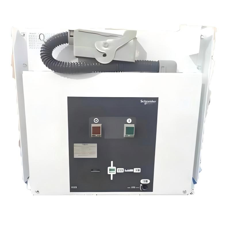
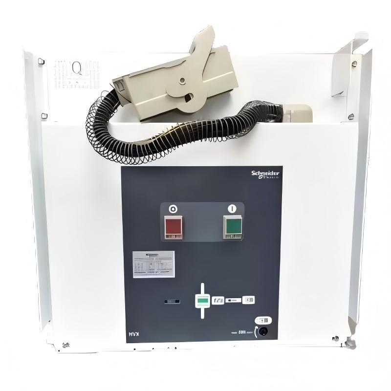
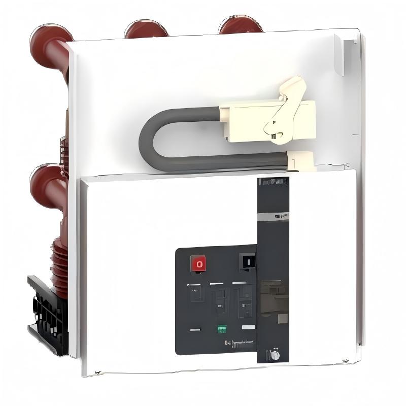
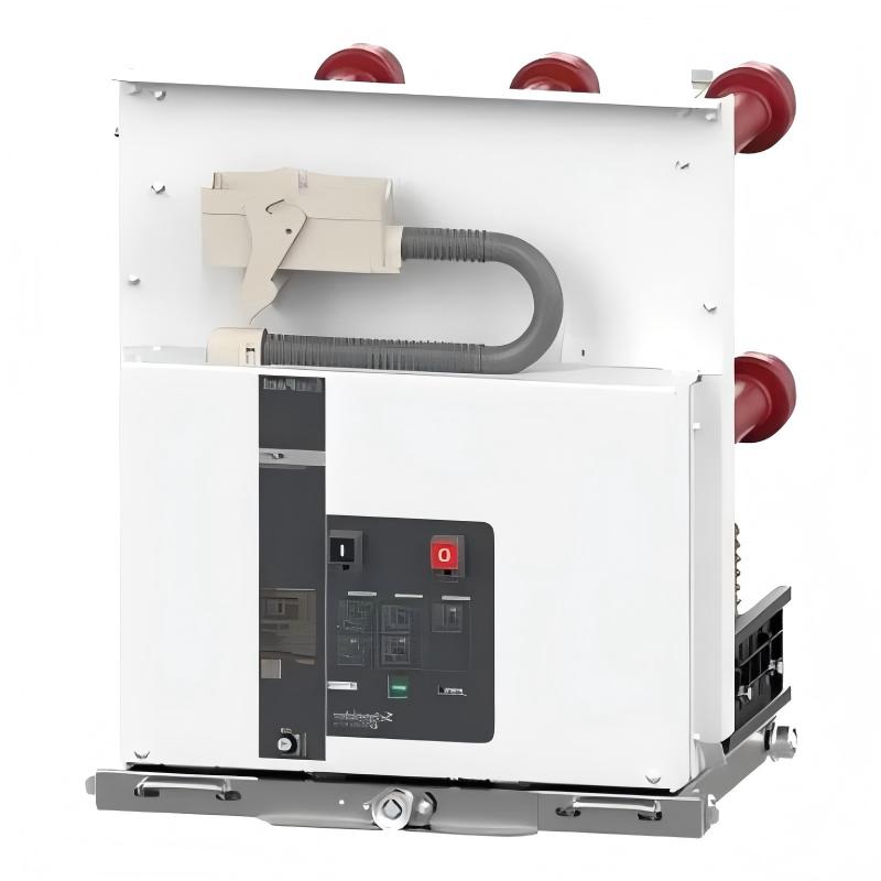
- Schneider
- HVX 24-31-16-E
- Vacuum Circuit Breaker
- France
- 691.5 x 653 x 640 mm
- 0.255 kg
- Xiamen, China
- New & In Stock
- T/T, PayPal, Western Union
- 1 Year
- 1-3 Working Days
- DHL, UPS, TNT, FedEx and EMS.
- 24-Hour Service
- COO
- 5
Our advantage

Global Logistics
We have a 10-year logistics and express cooperation agreement, so our products can be shipped to any place in the world.

Brand new and original
Our products are imported in bulk from the place of origin. Because of the cooperative relationship, our products are all original and 100% new.

24-hour service
We provide 7*24 hours service to our customers. We will be there whenever you need us.

Price advantage
All our products are priced very favorably because we have our own warehouse and supply.
| Company Information | |||
| [email protected] | |||
| Mobile | +8615980777398 | ||
| +8615980777398 | |||
| 15980777398 |
Product Overview
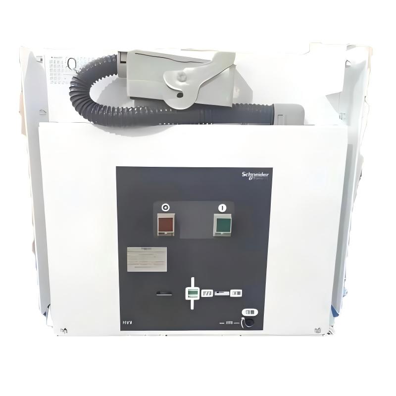
The Schneider Electric HVX 24-31-16-E Vacuum Circuit Breaker is a medium-voltage switching device designed for electrical distribution systems operating at a rated voltage of 24 kV. It belongs to the HVX vacuum circuit breaker family, which is used in medium-voltage switchgear applications requiring controlled circuit switching, fault interruption, and reliable electrical isolation within a properly engineered system.
Vacuum circuit breakers interrupt electrical current by separating contacts inside a sealed vacuum interrupter. When the contacts open, an arc forms briefly and is extinguished as the current passes through zero, allowing the circuit to be interrupted. This switching principle is widely used in medium-voltage equipment because it supports effective arc interruption without relying on oil as the arc-quenching medium.
The HVX 24-31-16-E configuration is associated with a rated voltage of 24 kV, a rated short-circuit breaking current of 31.5 kA, and a rated normal current of 1,600 A. These electrical ratings are important when evaluating the circuit breaker’s suitability for a distribution feeder, transformer circuit, industrial substation, or other medium-voltage installation.
The “E” designation is associated with a withdrawable configuration in the HVX range. Withdrawable circuit breakers are installed on a compatible mechanism or truck so that the breaker can be moved between defined service and disconnected positions in accordance with the switchgear design. This arrangement can facilitate maintenance and equipment replacement while supporting the interlocking procedures built into the switchgear.
The exact breaker configuration, contact arrangement, operating mechanism, auxiliary circuits, and switchgear compatibility must be confirmed against the product nameplate and the relevant technical drawings. Medium-voltage circuit breakers are not interchangeable solely because their rated voltage and current appear similar.
Technical Specifications
| Parameter | Specification |
|---|---|
| Brand | Schneider Electric |
| Product Series | HVX |
| Model | HVX 24-31-16-E |
| Product Type | Vacuum Circuit Breaker |
| Application | Medium-voltage electrical distribution |
| Rated Voltage | 24 kV |
| Rated Short-Circuit Breaking Current | 31.5 kA |
| Rated Normal Current | 1,600 A |
| Rated Frequency | Typically 50/60 Hz; verify the exact configuration |
| Arc-Interruption Medium | Vacuum |
| Configuration | Withdrawable type associated with the “E” designation |
| Installation | Compatible medium-voltage switchgear |
| Dimensions Provided | 691.5 × 653 × 640 mm |
| Weight Provided | 0.255 kg — requires verification |
| Approximate Reference Weight for Related Configuration | 255 kg fixed type / 280 kg withdrawable type, depending on configuration |
| Typical Applications | Industrial substations, distribution feeders, transformer circuits, and medium-voltage switchgear |
Important: The dimensions and weight supplied in the product listing should be verified against the exact unit. The 0.255 kg weight is inconsistent with a complete medium-voltage circuit breaker and may reflect a unit conversion or data-entry error. The reference weights for related HVX configurations are not a substitute for the exact model’s nameplate or shipping documentation.
Function and Working Principle
The HVX 24-31-16-E is designed to establish, carry, and interrupt electrical current within the limits of its rated operating conditions. Its operation depends on the vacuum interrupter, operating mechanism, control circuits, and the switchgear interlocking system.
1. Vacuum Arc Interruption
The vacuum interrupter contains electrical contacts in a sealed enclosure. When the breaker receives an opening command, the operating mechanism separates the contacts. An electrical arc forms between the contacts during interruption, and the vacuum environment supports rapid extinction of the arc.
This process enables the breaker to interrupt current without using oil as the arc-quenching medium. The interrupter’s integrity and the condition of its mechanical operating components are important to reliable performance.
2. Normal Current Carrying
When the circuit breaker is closed, its main contacts conduct current to the connected circuit. The 1,600 A rated normal current is a key selection parameter, but the actual permissible continuous current also depends on the switchgear arrangement, ambient conditions, installation design, and applicable manufacturer specifications.
Engineers should verify the busbar ratings, terminal connections, temperature-rise limits, and other switchgear characteristics before placing the breaker into service.
3. Short-Circuit Interruption
Electrical faults can produce currents far above normal operating levels. The circuit breaker is designed to interrupt fault current within its specified short-circuit breaking capability when used in a correctly rated system.
The 31.5 kA rating is an important parameter for system protection coordination. The prospective fault current at the installation point must not exceed the capability of the selected equipment. The protection relay and associated trip circuit must also be correctly configured to initiate the required breaker operation.
4. Opening and Closing Mechanism
A medium-voltage circuit breaker uses an operating mechanism to move its contacts between open and closed positions. Depending on the exact configuration, the mechanism may incorporate spring charging, electrical opening and closing coils, position indication, and auxiliary contacts.
These components allow the breaker to respond to control commands from local operating circuits or a wider substation automation system. The exact coil voltages, auxiliary-contact arrangement, and operating sequence must be verified from the unit’s electrical diagrams.
5. Interlocking and Safe Operation
Withdrawable circuit breakers operate within a switchgear assembly designed to control movement between service and disconnected positions. Mechanical and electrical interlocks help prevent prohibited operations, such as moving the breaker under conditions not permitted by the switchgear design.
Interlocks must never be bypassed as a routine operating method. Maintenance and switching procedures must follow the specific switchgear instructions and applicable electrical safety requirements.
Role in Medium-Voltage Electrical Distribution
The HVX 24-31-16-E can serve as a switching and protection component within a medium-voltage distribution network. Its role is determined by the circuit design, protection scheme, and the switchgear assembly in which it is installed.
1. Feeder Protection
Distribution feeders supply power from a busbar or substation to downstream equipment. A circuit breaker can connect or disconnect the feeder and interrupt fault current when commanded by the protection system.
The breaker must be coordinated with the protection relay, current transformers, and the electrical characteristics of the network.
2. Transformer Circuit Switching
Medium-voltage circuit breakers are commonly used in transformer feeder arrangements where controlled switching and fault interruption are required. A properly engineered installation coordinates the breaker with transformer protection and upstream and downstream protective devices.
The breaker itself does not replace transformer differential protection, overcurrent protection, temperature monitoring, or other required protection functions.
3. Industrial Substations
Industrial facilities often distribute power through medium-voltage switchgear to transformers, large motors, and other electrical loads. A vacuum circuit breaker can provide the switching and interruption function within this infrastructure.
Correct equipment selection requires checking rated voltage, normal current, short-circuit breaking capability, insulation levels, and the mechanical interface with the switchgear.
4. Switchgear Maintenance and Replacement
A withdrawable design can support planned maintenance by allowing the breaker to be moved out of its service position according to the manufacturer’s procedure. This may help maintenance teams inspect or replace the breaker without dismantling the entire switchgear assembly.
However, withdrawability does not mean the equipment is safe to remove under any operating condition. The circuit must be isolated, the required interlocks observed, and the absence of hazardous voltage established according to approved procedures.
Industrial Applications
1. Industrial Power Distribution
Manufacturing plants, processing facilities, and large commercial installations may use medium-voltage switchgear to distribute incoming electrical power. The HVX 24-31-16-E’s rated voltage and current class can be relevant to suitably designed 24 kV systems.
The final selection must account for the actual network voltage, load current, fault level, and switchgear design.
2. Transformer Feeders
Transformers supplying low-voltage distribution boards or industrial loads may be connected through medium-voltage breaker compartments. A circuit breaker provides a means of switching the transformer circuit and interrupting faults within its rated capability.
Protection settings and the coordination between the breaker, transformer, and upstream equipment must be engineered for the installation.
3. Utility and Substation Switchgear
Medium-voltage substations use circuit breakers to control outgoing feeders and selected equipment circuits. The breaker may be operated locally or through a substation control system, depending on the design.
The 31.5 kA short-circuit breaking rating must be evaluated against the maximum prospective fault current at the installation point.
4. Large Industrial Facilities
Facilities with substantial electrical demand may use medium-voltage distribution to reduce the number of low-voltage feeders and support efficient power distribution across a site. Vacuum circuit breakers can form part of the switching and protection infrastructure.
Environmental conditions, maintenance access, protection coordination, and the switchgear manufacturer’s requirements remain important to reliable operation.
5. Infrastructure and Process Plants
Water treatment plants, mining facilities, manufacturing complexes, and other process installations may use medium-voltage switchgear to control power distribution. The breaker can be considered where its electrical and mechanical specifications match the application.
Suitability should be established through engineering review rather than by relying on the product family name alone.
Installation and System Integration
Medium-voltage circuit breaker installation must be performed by appropriately qualified electrical personnel using the manufacturer’s documentation and the applicable safety procedures.
1. Verify the Complete Model
Check the complete model designation, nameplate ratings, serial number, and any configuration suffixes. Confirm the rated voltage, normal current, short-circuit breaking capability, and withdrawable arrangement.
The model number alone should not be used to infer every auxiliary circuit or accessory supplied with the unit.
2. Confirm Switchgear Compatibility
A withdrawable breaker must match the receiving switchgear compartment. Verify the mechanical dimensions, phase spacing, primary contact arrangement, secondary connector, racking mechanism, and interlocking system.
A breaker that has the correct electrical ratings may still be unsuitable if its mechanical interface or secondary wiring differs from the installed switchgear.
3. Check Installation Dimensions and Weight
The supplied dimensions are 691.5 × 653 × 640 mm. Confirm their orientation and measurement points against the manufacturer’s dimensional drawing before using them for cabinet planning or replacement work.
The supplied weight of 0.255 kg is not credible for a complete medium-voltage breaker. Related HVX configurations are listed at weights measured in hundreds of kilograms, with the exact value depending on the type and configuration. Use the verified unit weight when designing lifting arrangements, transport packaging, and handling procedures.
4. Inspect Primary and Secondary Connections
Inspect the main contacts, primary disconnect contacts, secondary connector, control wiring, grounding arrangements, and mechanical components according to the maintenance instructions.
Any damage, contamination, corrosion, or abnormal wear should be assessed before the equipment is energized. Do not modify terminals or wiring based on assumptions about another breaker model.
5. Integrate Protection and Control Circuits
The circuit breaker may receive trip and close commands through local control circuits, protection relays, or substation automation equipment. The precise arrangement depends on the installed configuration.
Confirm the control voltage, trip-coil and closing-coil specifications, auxiliary contacts, position signals, and relay interfaces. Test the complete trip path and relevant interlocks before returning the breaker to service.
6. Commissioning and Functional Testing
Commissioning should include the checks and tests specified by the manufacturer and the site’s approved procedures. These may include mechanical operation, contact and circuit checks, control-circuit verification, interlock testing, and suitable electrical tests performed by qualified personnel.
Record the results and retain them with the equipment’s maintenance documentation.
Compatible System Components
The HVX 24-31-16-E functions as part of a complete medium-voltage switchgear and protection system. Compatibility must be established for the exact breaker configuration.
| Component | Function | Compatibility Considerations |
|---|---|---|
| Medium-voltage switchgear compartment | Houses and supports the circuit breaker | Verify mechanical dimensions, phase spacing, and interface design |
| Protection relay | Detects electrical faults and issues trip commands | Confirm protection functions, settings, and trip-circuit compatibility |
| Current transformers | Provide current signals for protection and measurement | Check ratio, accuracy class, burden, and protection requirements |
| Voltage transformers or voltage sensors | Provide voltage signals where required | Confirm system design and relay input requirements |
| Trip coil | Opens the circuit breaker when energized | Verify rated control voltage and wiring |
| Closing coil | Commands breaker closing | Confirm coil ratings and closing-circuit design |
| Spring charging mechanism | Stores mechanical energy for operation, where fitted | Verify mechanism type, motor supply, and charging status indication |
| Auxiliary contacts | Report breaker status to control systems | Confirm contact arrangement and ratings |
| Secondary control connector | Connects the breaker to switchgear control wiring | Verify connector type and pin assignment |
| Racking and interlocking mechanism | Supports movement and safe positioning of a withdrawable breaker | Must match the switchgear design and approved operating sequence |
These are system-level components and are not necessarily supplied with the breaker. Confirm the complete bill of materials before procurement.
Alternative Models and Replacement Considerations
When replacing an HVX vacuum circuit breaker, selection must be based on electrical, mechanical, and control compatibility rather than nominal voltage alone.
| Replacement Option | Evaluation Points |
|---|---|
| Identical Schneider Electric HVX 24-31-16-E | Preferred starting point for a like-for-like replacement; verify series, condition, interfaces, and accessories |
| Another HVX 24 kV configuration | Check current rating, short-circuit breaking rating, phase spacing, fixed or withdrawable design, and mechanism details |
| Another Schneider Electric medium-voltage breaker | Requires confirmation of the switchgear interface, insulation levels, protection coordination, and control circuits |
| A breaker from another manufacturer | May require switchgear modifications, interface engineering, revised wiring, and formal type/design compatibility review |
Before approving a replacement, compare:
- Rated voltage and insulation levels.
- Rated normal current.
- Rated short-circuit breaking current and required fault withstand capability.
- Phase spacing and primary contact dimensions.
- Fixed or withdrawable configuration.
- Mechanical racking and interlocking arrangements.
- Trip and closing coil voltages.
- Auxiliary-contact configuration.
- Secondary connector and wiring.
- Switchgear compartment dimensions and clearances.
- Applicable standards and commissioning requirements.
A replacement must be approved for the actual switchgear application. A breaker with similar electrical ratings is not automatically a safe mechanical or electrical substitute.
Key Advantages
Vacuum Arc-Interruption Technology
Vacuum interruption provides an established method for extinguishing the arc during medium-voltage circuit switching without using oil as the arc-quenching medium.
High-Current Switching Capability
The 1,600 A normal-current rating supports applications requiring substantial continuous current, subject to the complete switchgear design and installation conditions.
Short-Circuit Interruption
The specified 31.5 kA short-circuit breaking rating provides an important selection criterion for systems with significant prospective fault currents.
Withdrawable Configuration
The withdrawable arrangement can facilitate maintenance and replacement when used with its compatible switchgear compartment and the prescribed operating procedures.
Integration with Protection Systems
The breaker can be incorporated into a coordinated protection system using suitable relays, current transformers, control circuits, and auxiliary signals.
Medium-Voltage Distribution Applications
The HVX family is designed for medium-voltage switchgear applications. Correct configuration and installation are essential to achieving the required switching and protection performance.
Technical FAQs
1. What is the Schneider Electric HVX 24-31-16-E?
It is a medium-voltage vacuum circuit breaker associated with a 24 kV rated voltage, 31.5 kA rated short-circuit breaking current, and 1,600 A rated normal current.
2. What does the 24-31-16 designation mean?
The model designation corresponds to a 24 kV voltage class, a 31.5 kA short-circuit breaking class, and a 1,600 A normal-current rating in the relevant HVX selection data. Always confirm the exact configuration against the applicable product documentation.
3. What is the function of a vacuum circuit breaker?
It establishes, carries, and interrupts current in an electrical circuit. During opening, its contacts separate inside a vacuum interrupter, where the arc is extinguished as part of the interruption process.
4. Is the HVX 24-31-16-E a withdrawable breaker?
The “E” designation is associated with the withdrawable type in the HVX range. Verify the nameplate and the switchgear interface before ordering a replacement.
5. Can it be installed in any 24 kV switchgear panel?
No. The breaker must match the compartment’s mechanical and electrical interfaces, including contact arrangement, phase spacing, racking mechanism, secondary connector, and interlocks.
6. Is 0.255 kg the correct weight?
It is unlikely to be the weight of the complete circuit breaker. Related HVX configurations have reference weights of approximately 255 kg for fixed versions and 280 kg for withdrawable versions, depending on the configuration. Verify the exact unit weight before transport or installation.
7. What should be checked before purchasing a used breaker?
Confirm the complete model number, nameplate ratings, serial number, physical condition, operating mechanism, primary contacts, auxiliary circuits, and compatibility with the receiving switchgear. Request available test records and confirm the seller’s condition and warranty terms.
8. What maintenance is required?
Maintenance should follow the manufacturer’s schedule and may include inspection of the mechanism, primary contacts, auxiliary circuits, interlocks, control wiring, and relevant electrical performance. The scope and test intervals depend on the installation and operating conditions.
9. Can the breaker be removed while the switchgear is energized?
Never assume it is safe to withdraw the breaker while the switchgear is energized. Follow the exact manufacturer’s switching sequence, isolation requirements, interlocking instructions, and site safety procedures. Only qualified personnel should perform the work.
10. Why are the listed dimensions and weight important?
Dimensions determine whether the breaker fits the switchgear compartment, while weight affects transport, lifting equipment, and handling procedures. Incorrect data can create serious installation and safety problems, so both should be verified against the actual unit and manufacturer drawings.
Procurement and Maintenance Recommendations
When sourcing the Schneider Electric HVX 24-31-16-E, begin by confirming the complete model designation and the requirements of the installed switchgear. Verify the rated voltage, normal current, short-circuit breaking capability, withdrawable arrangement, primary contact spacing, secondary connector, and control-circuit specifications.
For used or refurbished equipment, request clear photographs of the nameplate, primary contacts, operating mechanism, and secondary connector. Where available, review functional test reports and maintenance history. Confirm whether the breaker includes the required accessories and whether it has been tested for the intended service.
The product listing currently specifies dimensions of 691.5 × 653 × 640 mm and a weight of 0.255 kg. The dimensions should be checked against the exact dimensional drawing, and the weight should be corrected or confirmed before publication. For logistics and installation, distinguish the net equipment weight from the packaged shipping weight.
Maintenance should be carried out by qualified personnel using the manufacturer’s procedures. Inspect mechanical operation, contacts, interlocks, auxiliary circuits, and control wiring at the intervals specified for the actual installation. Record maintenance findings and functional test results for future troubleshooting.
For replacement projects, evaluate the breaker and switchgear as a complete system. Confirm mechanical fit, insulation requirements, protection coordination, control wiring, and interlock compatibility before approving a substitute.
Conclusion
The Schneider Electric HVX 24-31-16-E Vacuum Circuit Breaker is designed for medium-voltage electrical distribution applications. Its associated ratings of 24 kV, 31.5 kA short-circuit breaking current, and 1,600 A normal current make it relevant to suitably engineered switchgear installations in industrial and infrastructure environments.
Successful installation and replacement depend on more than the headline electrical ratings. The switchgear interface, withdrawable mechanism, protection circuits, control-coil specifications, and maintenance condition must all be verified. The supplied weight of 0.255 kg should be checked carefully because it is inconsistent with the expected weight of a complete medium-voltage breaker.