

ProductPRODUCT
Featured products
Contact Us
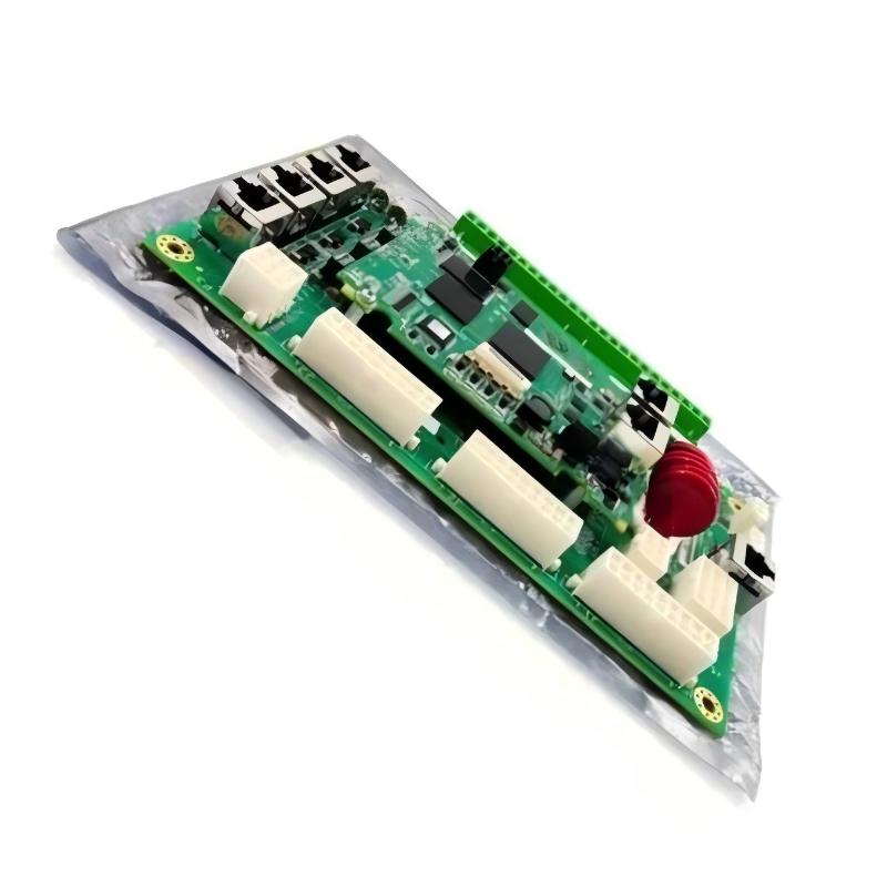
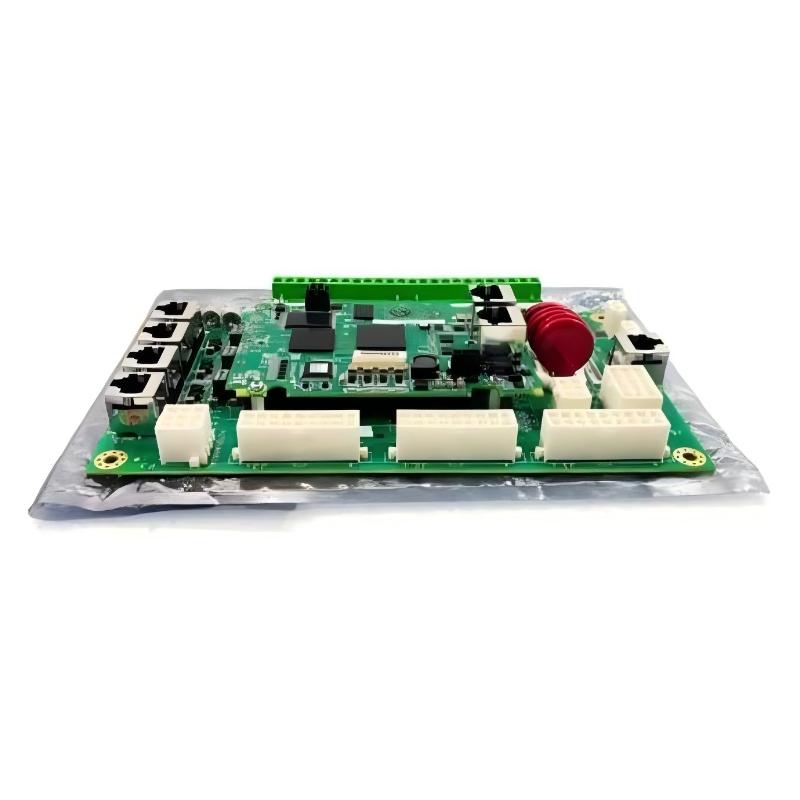
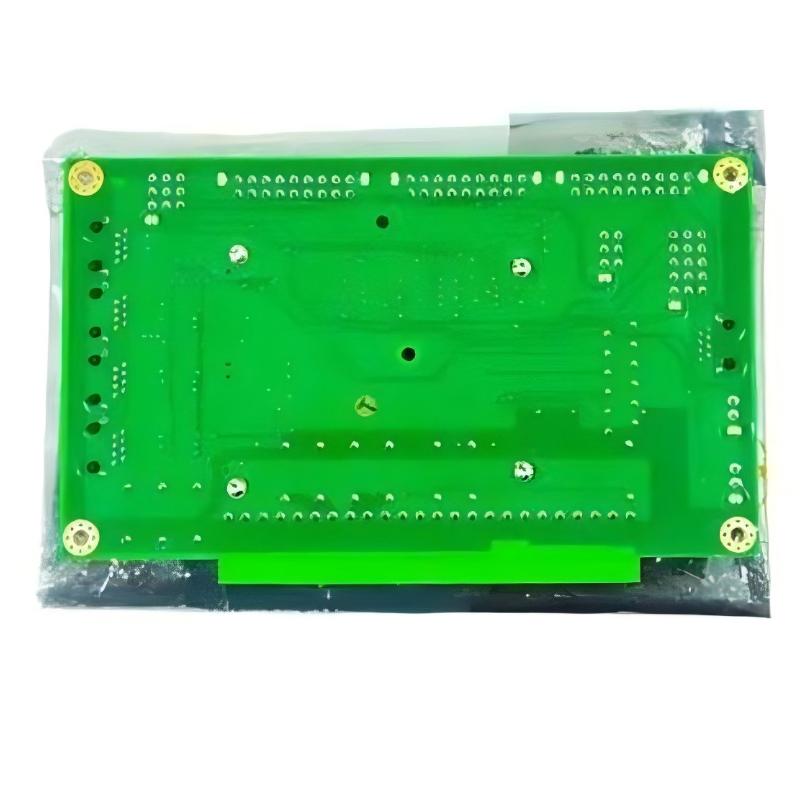
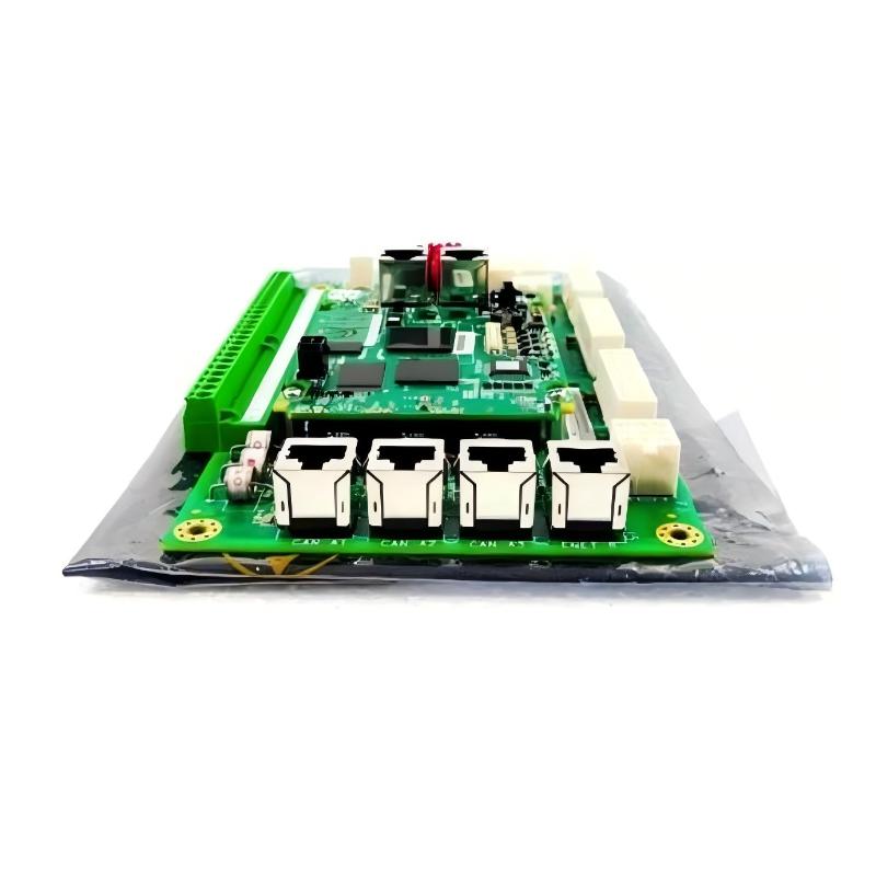
- GE
- IS400UCLIH1A
- Application Control Layer Module
- USA
- 158 x 120 x 30 mm
- 0.3 kg
- Xiamen, China
- New & In Stock
- T/T, PayPal, Western Union
- 1 Year
- 1-3 Working Days
- DHL, UPS, TNT, FedEx and EMS.
- 24-Hour Service
- COO
- 12
Our advantage

Global Logistics
We have a 10-year logistics and express cooperation agreement, so our products can be shipped to any place in the world.

Brand new and original
Our products are imported in bulk from the place of origin. Because of the cooperative relationship, our products are all original and 100% new.

24-hour service
We provide 7*24 hours service to our customers. We will be there whenever you need us.

Price advantage
All our products are priced very favorably because we have our own warehouse and supply.
| Company Information | |||
| [email protected] | |||
| Mobile | +8615980777398 | ||
| +8615980777398 | |||
| 15980777398 |
Product Overview
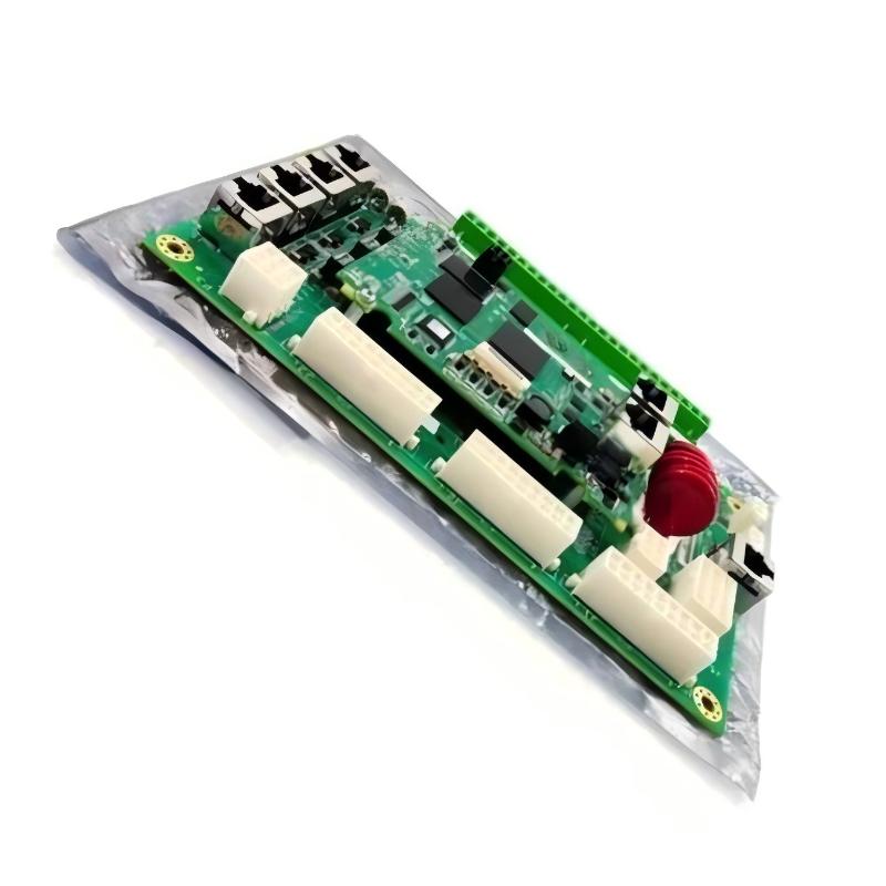
The GE IS400UCLIH1A Application Control Layer Module is an industrial automation component identified by its GE IS400 series model designation. Application-level control hardware can form part of a larger automation architecture, where control functions, equipment interfaces, and system-level operations are coordinated to support industrial processes. The precise responsibilities of the IS400UCLIH1A depend on its intended host system and the configuration in which it is installed.
Modern industrial automation systems often consist of multiple hardware and software layers. These may include control processors, I/O interfaces, communication assemblies, operator interfaces, and application-specific control components. Each element must operate within the architecture defined for the installation. Correctly identifying the Application Control Layer Module is therefore important when maintaining existing equipment, planning a system upgrade, or sourcing replacement hardware.
The GE IS400UCLIH1A has listed dimensions of 158 × 120 × 30 mm and a weight of approximately 0.3 kg. Its compact physical profile can simplify handling, equipment identification, and installation-space planning. These specifications are also useful for spare-parts inventory and replacement logistics.
The model’s exact processor capabilities, supported applications, communication interfaces, electrical requirements, and compatibility with other GE assemblies should be verified against the applicable equipment documentation. The product designation provides a useful identification reference, but it should not be used alone to infer specific performance ratings or supported functions.
Technical Specifications
| Parameter | Specification |
|---|---|
| Manufacturer | General Electric (GE) |
| Model Number | IS400UCLIH1A |
| Product Type | Application Control Layer Module |
| Product Series | GE IS400 Series |
| Primary Application | Industrial control and automation |
| Control Function | Application-level control support, subject to system configuration |
| Processor Architecture | Verify from the applicable technical documentation |
| Memory Capacity | Verify from the applicable technical documentation |
| Communication Interfaces | Verify from the applicable technical documentation |
| Supported Protocols | Verify from the applicable technical documentation |
| Power Requirements | Verify from the equipment documentation |
| I/O Support | Verify from the host-system configuration |
| Installation | Compatible industrial control equipment |
| Dimensions | 158 × 120 × 30 mm |
| Weight | 0.3 kg |
| Replacement Requirement | Confirm full part number, revision, and host-system compatibility |
Note: Dimensions and weight are based on the supplied product information. Detailed electrical, communication, processing, and compatibility specifications should be confirmed before installation.
What Is the GE IS400UCLIH1A Application Control Layer Module?
An application control layer is generally associated with the execution or coordination of control functions defined for a particular industrial system. Depending on the architecture, application-level control can connect equipment-level operations with higher-level process requirements, helping coordinate operating sequences, system responses, and control tasks.
The GE IS400UCLIH1A is identified as an Application Control Layer Module. Its precise role within a specific GE installation should be established by examining the host equipment, assembly identification, system configuration, and applicable technical documentation.
In industrial automation, not all control modules perform the same function. A processor module, communication interface, signal-processing board, and application-control component may have similar physical characteristics while supporting different operations. Their electrical interfaces, software dependencies, and replacement requirements may also differ.
For maintenance and procurement purposes, the IS400UCLIH1A should be treated as a model-specific component. Its supported functions and relationship with other assemblies should be verified before it is installed or substituted for existing hardware.
Function and Working Principle
1. Supporting Application-Level Control
Application-level control hardware may support functions associated with the operation of a particular machine, subsystem, or industrial process. These functions are determined by the control architecture and the configuration of the installed equipment.
The specific application-control responsibilities assigned to the IS400UCLIH1A should be confirmed from the host-system documentation rather than inferred from its product name.
2. Coordinating Control Functions
Industrial automation systems frequently divide responsibilities among different hardware components. One component may acquire signals, another may process control logic, and another may support communication or application-specific operations.
A module within this architecture must operate according to the interfaces and configuration defined for the complete system. Correct integration helps ensure that information is handled by the intended component and that related equipment functions remain coordinated.
3. Interfacing With Other Control Hardware
Control modules commonly operate alongside other electronic assemblies, I/O interfaces, power supplies, and communication components. The exact relationship between these elements depends on the platform and installation.
Before integrating the IS400UCLIH1A, verify the required hardware interfaces, connection assignments, power conditions, and any configuration dependencies specified for the host system.
4. Supporting System Operation
In a configured automation system, application-control functions may contribute to equipment sequencing, operating-state management, or the coordination of process tasks. The functions available depend on the installed control program and the hardware architecture.
The module’s individual capabilities should not be confused with the capabilities of the complete control system. Overall system performance depends on the controller, connected devices, configuration, and application requirements.
5. Supporting Diagnostics and Maintenance
Industrial control systems may provide diagnostic information to help maintenance personnel identify abnormal operating conditions. Depending on the platform, these diagnostics may be available through hardware indicators, engineering tools, system logs, or supervisory interfaces.
The diagnostic features specifically supported by the IS400UCLIH1A should be verified before developing a maintenance procedure.
Role in Industrial Automation Systems
The GE IS400UCLIH1A can be evaluated as part of an industrial control architecture in which application-related hardware supports the coordinated operation of connected equipment.
A typical industrial automation architecture may include several functional layers:
- Field layer: Sensors, transmitters, actuators, and equipment interfaces.
- I/O layer: Hardware that acquires or provides electrical signals.
- Control layer: Hardware and software responsible for configured control logic.
- Application layer: Functions associated with equipment or process operation.
- Supervisory layer: Operator interfaces, monitoring systems, and higher-level coordination tools.
These layers are conceptual descriptions of common automation architectures. The exact organization and responsibilities of the IS400UCLIH1A must be confirmed for the installed system.
When a control module is replaced, compatibility involves more than physical dimensions. Hardware revision, configuration requirements, communication interfaces, and relationships with other assemblies may all affect whether the replacement can operate correctly.
Maintenance personnel should therefore identify the module’s position in the control architecture before disconnecting or replacing it.
Industrial Applications
The following examples describe general applications for industrial control systems. They do not independently confirm that the IS400UCLIH1A supports every application listed.
Manufacturing Automation
Manufacturing facilities use automation systems to coordinate machine operations, monitor equipment status, and execute production sequences. Application-related control hardware may contribute to these functions when supported by the installed architecture.
Industrial Machinery
Industrial machines may require coordinated operation of motors, sensors, actuators, and auxiliary equipment. Application-level control functions can help organize machine behavior according to a configured operating sequence.
Process Control
Process facilities use control systems to manage equipment and monitor operating conditions. Application-control functions may form part of the wider system responsible for maintaining the required operating sequence and responding to process changes.
Material Handling Systems
Conveyors, transfer stations, and other material-handling equipment often require coordination between multiple devices. A compatible control architecture can manage operating states and equipment interactions.
Industrial Utilities
Utility installations may use automation to coordinate pumps, fans, auxiliary equipment, and monitoring devices. The suitability of a particular module depends on the actual system design and the module’s verified capabilities.
Control-System Maintenance and Modernization
Industrial facilities may need to replace aging electronic assemblies, maintain spare modules, or restore existing control equipment after a failure. Accurate identification of the installed module helps reduce the risk of selecting incompatible hardware.
Installation and System Integration
Correct installation of the GE IS400UCLIH1A requires confirmation of its intended function and compatibility with the host equipment. The following general procedure should be adapted to the applicable installation instructions.
1. Verify the Product Identification
Confirm the complete model number IS400UCLIH1A before removing or installing the component.
Record relevant identification details, including:
- Full part number
- Hardware revision or additional markings
- Existing installation location
- Associated control assemblies
- Connector arrangement
- Host-system identification
- Available fault or diagnostic information
Do not assume that a module with a similar enclosure or model designation is interchangeable.
2. Review Host-System Requirements
Identify the equipment in which the module is installed and verify the applicable hardware configuration. Check the specified power requirements, interfaces, mounting arrangement, and any required configuration or software dependencies.
The exact requirements should come from the documentation for the installed system.
3. Isolate the Equipment Safely
Before performing maintenance, follow the site’s electrical safety procedures and applicable lockout/tagout requirements. Isolate the relevant energy sources and verify that the equipment is safe to handle.
Only qualified personnel should perform installation or replacement work on industrial control equipment.
4. Check Physical Clearance
The listed dimensions are 158 × 120 × 30 mm, with a weight of 0.3 kg. Use these values as initial references when assessing the installation space.
Also account for connectors, wiring bends, mounting hardware, ventilation requirements, and access needed for future inspection or replacement. Confirm the actual mounting arrangement from the equipment documentation.
5. Inspect Connectors and Associated Wiring
Check the relevant connectors and wiring for physical damage, contamination, corrosion, or loose connections. Record existing connection assignments before disconnecting the module.
Avoid changing wiring or connector assignments based solely on appearance.
6. Confirm Configuration Requirements
Determine whether the replacement procedure requires restoration of configuration data, application settings, hardware definitions, or other system-specific information.
Use only configuration files and procedures confirmed as suitable for the installed hardware. A backup intended for a different hardware revision or control platform may not be appropriate.
7. Perform Commissioning Checks
After installation, follow the approved commissioning procedure. Check the hardware status, system diagnostics, and relevant interfaces. Where applicable, verify that the host system recognizes the module and that the associated application functions operate as expected.
Testing should be conducted under controlled conditions before the equipment returns to normal operation.
8. Update Maintenance Records
Record the replacement part number, revision information, installation date, configuration actions, and commissioning results. Accurate records help future technicians identify the installed hardware and investigate subsequent faults.
Troubleshooting the GE IS400UCLIH1A
Troubleshooting should begin with the complete control system rather than assuming that every abnormal condition originates from the application-control module.
Module Does Not Operate as Expected
Potential areas to investigate include:
- Power supply and connections
- Connector seating
- Hardware installation
- Host-system configuration
- Compatibility with associated components
- Available diagnostic indicators
- Faults reported by the wider control system
Use the approved diagnostic procedure for the specific installation to narrow down the cause.
Communication or Interface Problems
If the host system cannot communicate with the module or associated equipment, inspect the documented interface path. Check connectors, associated interface hardware, configuration settings, and available diagnostic information.
The supported communication method must first be established from the actual hardware documentation. Do not assume that a particular network protocol is supported based solely on the model number.
Unexpected Control Behavior
Unexpected behavior may result from incorrect configuration, a problem with connected hardware, an input signal issue, or a fault elsewhere in the control architecture.
Review recent configuration changes and compare the current operating conditions with the expected control sequence. Determine whether the issue affects one function or multiple related functions.
Intermittent Operation
Intermittent faults can be associated with loose connections, damaged wiring, unstable power, environmental conditions, configuration problems, or faults in related equipment.
Record the conditions under which the issue occurs. Fault logs, system status information, and a history of recent maintenance can help identify the underlying cause.
Repeated Faults After Replacement
If the same problem persists after replacing the module, investigate the surrounding system. Check associated hardware, power conditions, configuration, connectors, and the compatibility of the replacement.
Repeated replacement without identifying the root cause can increase maintenance costs and extend equipment downtime.
Maintenance Recommendations
A structured maintenance program can help improve the reliability of industrial control assemblies.
Visual Inspection
Inspect the module and surrounding installation for physical damage, contamination, corrosion, loose mounting hardware, and signs of overheating.
Connector Inspection
Check accessible connectors and wiring for damage, contamination, and mechanical strain. Follow the specified procedure before disconnecting or reconnecting hardware.
Environmental Management
Maintain the control cabinet within the environmental limits specified for the installed equipment. Appropriate protection from dust, moisture, excessive temperature, and vibration can help reduce the risk of premature failure.
Configuration Backup
Maintain current and verified backups of applicable system configuration data. Record the hardware revision and system version associated with each backup to simplify recovery.
Diagnostic Recordkeeping
Document faults, diagnostic messages, operating symptoms, and corrective actions. A clear history of events can help distinguish recurring hardware issues from configuration or system-level problems.
Spare-Parts Management
Store spare modules under suitable conditions and label them with their complete part numbers and revision information. Confirm compatibility before installing a spare unit.
Compatible System Components
An application-control module may operate within a wider industrial control system containing several categories of equipment.
| Component Category | Typical Function |
|---|---|
| Control Processor | Executes configured control logic where applicable |
| Application-Control Hardware | Supports application-related functions defined by the system architecture |
| I/O Modules | Interface with field signals |
| Power Supply | Provides power to compatible control equipment |
| Communication Interfaces | Exchange data between supported devices |
| Terminal Assemblies | Organize electrical connections |
| Operator Interface | Displays system status and operating information |
| Supervisory Control System | Supports monitoring and higher-level coordination |
| Field Sensors | Provide process or equipment measurements |
| Actuators and Drives | Carry out control actions under the system design |
These are general component categories, not a verified list of specific products compatible with the IS400UCLIH1A. The exact supported hardware and system relationships must be confirmed from the applicable technical documentation.
Replacement and Procurement Considerations
Selecting a replacement for the GE IS400UCLIH1A requires checking both the physical product and its relationship with the installed control architecture.
Before ordering, verify:
- Full model number: Confirm IS400UCLIH1A exactly.
- Hardware revision: Record any additional revision markings.
- Product function: Confirm the module’s role in the host system.
- System compatibility: Verify the supported control platform and associated hardware.
- Electrical requirements: Confirm power and interface requirements from the documentation.
- Configuration requirements: Determine whether application data or settings must be restored.
- Physical dimensions: Confirm the listed size of 158 × 120 × 30 mm.
- Weight: Use the listed weight of 0.3 kg for handling and shipping planning.
- Product condition: Inspect for physical damage and verify identification markings.
Similar model numbers or matching dimensions do not guarantee functional interchangeability. Compatibility should be established before installation.
Key Advantages
Compact Physical Design
The listed dimensions of 158 × 120 × 30 mm provide a practical reference for cabinet planning and spare-parts handling.
Support for Application-Level Control Architecture
The product designation identifies the module as an application-control component, making correct identification important when maintaining a compatible industrial control system.
Easier Maintenance Planning
Accurate part identification and configuration records help maintenance teams plan replacement work and reduce avoidable troubleshooting delays.
Practical Inventory Management
The model number, dimensions, and weight provide useful information for cataloging, storage, and replacement logistics.
Integration Assessment for Industrial Automation
The IS400UCLIH1A can be evaluated for a particular application by verifying its intended role, configuration requirements, and compatibility with the host equipment.
Technical FAQs
What is the GE IS400UCLIH1A?
The GE IS400UCLIH1A is identified as an Application Control Layer Module associated with the GE IS400 series. Its precise hardware functions should be confirmed from the applicable system documentation.
What are the dimensions of the IS400UCLIH1A?
The listed dimensions are 158 × 120 × 30 mm.
How much does the GE IS400UCLIH1A weigh?
The listed weight is approximately 0.3 kg.
What does an Application Control Layer Module do?
The designation generally indicates a component associated with application-level functions in an industrial control architecture. The specific responsibilities of this model depend on its documented role and host-system configuration.
Which communication protocols does the IS400UCLIH1A support?
The supported interfaces and protocols should be verified from the applicable hardware documentation. They should not be inferred from the model number alone.
How should the IS400UCLIH1A be replaced?
Confirm the full part number, hardware revision, host-system compatibility, connection arrangement, and configuration requirements. Follow the approved isolation, installation, and commissioning procedures.
What can cause a module-related fault?
Potential causes include power problems, connector issues, configuration errors, incompatible hardware, environmental conditions, or faults in associated equipment.
Can another GE IS400 module replace the IS400UCLIH1A?
Not automatically. The replacement must be confirmed as compatible with the required function, hardware configuration, electrical interfaces, and host system.
What information should be recorded during maintenance?
Record the full model number, revision markings, installation location, fault information, configuration changes, and commissioning results. These details help improve traceability and future troubleshooting.
Conclusion
The GE IS400UCLIH1A Application Control Layer Module is an industrial automation component identified for application-control-related use within a compatible GE control architecture. Its precise responsibilities and supported interfaces depend on the installed hardware and system configuration.
With listed dimensions of 158 × 120 × 30 mm and a weight of 0.3 kg, the module’s physical specifications are useful for installation planning, spare-parts management, and replacement logistics. Physical compatibility alone, however, does not establish that a replacement will function correctly in the host system.
For reliable maintenance and integration, technicians and procurement teams should verify the complete model designation, hardware revision, configuration requirements, electrical interfaces, and compatibility with associated control equipment. Careful identification, systematic troubleshooting, and documented commissioning help support dependable industrial automation operation.