

ProductPRODUCT
Featured products
Contact Us
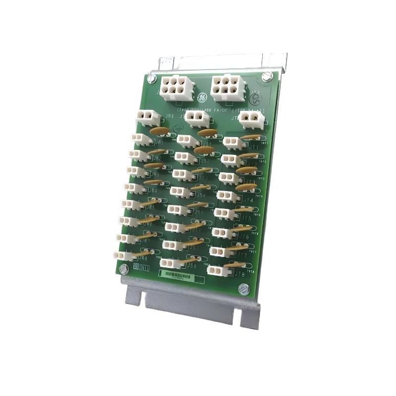
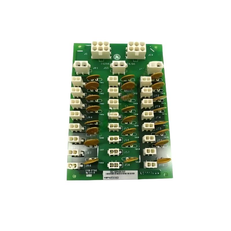
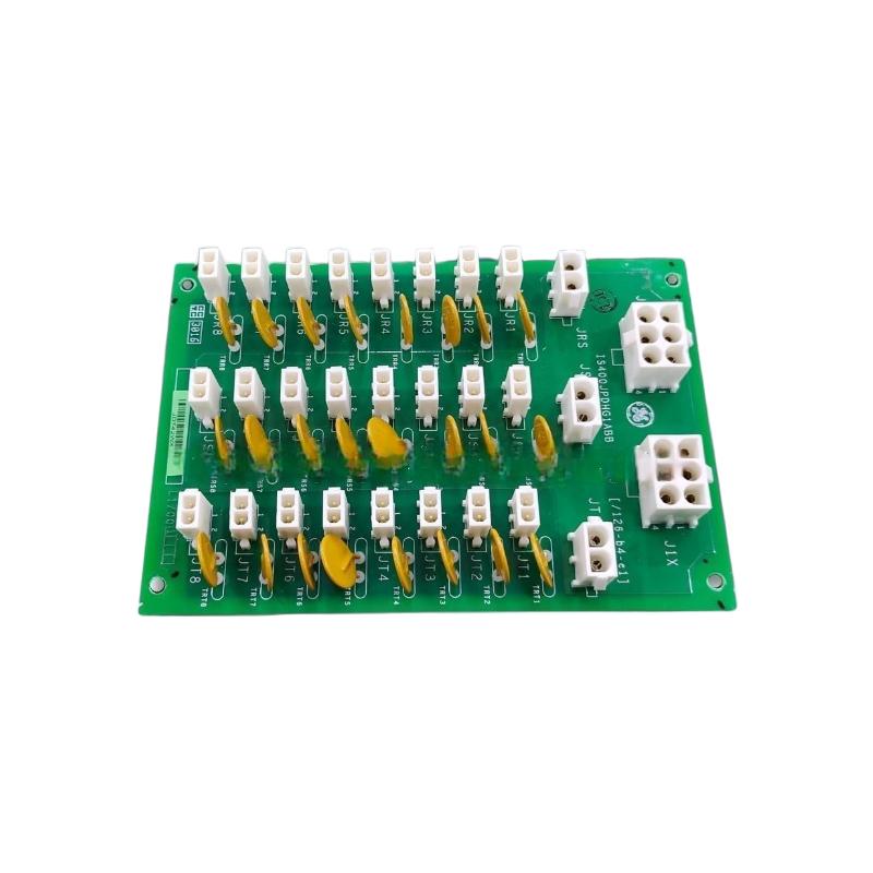

- GE
- IS400JPDHG1A
- High-Density Switchboard
- USA
- 158.75 x 60 x 107.95 mm
- 0.952 kg
- Xiamen, China
- New & In Stock
- T/T, PayPal, Western Union
- 1 Year
- 1-3 Working Days
- DHL, UPS, TNT, FedEx and EMS.
- 24-Hour Service
- COO
- 14
Our advantage

Global Logistics
We have a 10-year logistics and express cooperation agreement, so our products can be shipped to any place in the world.

Brand new and original
Our products are imported in bulk from the place of origin. Because of the cooperative relationship, our products are all original and 100% new.

24-hour service
We provide 7*24 hours service to our customers. We will be there whenever you need us.

Price advantage
All our products are priced very favorably because we have our own warehouse and supply.
| Company Information | |||
| [email protected] | |||
| Mobile | +8615980777398 | ||
| +8615980777398 | |||
| 15980777398 |
Product Overview
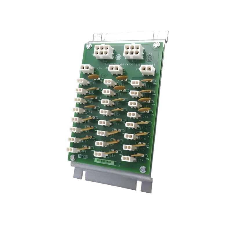
The GE IS400JPDHG1A High-Density Switchboard is an industrial control component identified by its GE IS400 series model designation. High-density switching and connection hardware can support the organization of multiple electrical circuits within a compact assembly, helping industrial control systems maintain structured connections between control equipment and associated electrical interfaces. The exact switching function and circuit arrangement of the IS400JPDHG1A should be confirmed against the equipment in which it is installed.
Industrial automation systems often contain numerous interconnected electronic assemblies, field circuits, power distribution components, and signal interfaces. Compact switching hardware can help accommodate connection requirements where cabinet space is limited and multiple circuits must be arranged within a defined installation area. Proper component identification and integration are essential to maintain reliable operation and simplify maintenance.
The GE IS400JPDHG1A is listed with dimensions of 158.75 × 60 × 107.95 mm and a weight of approximately 0.952 kg. These specifications are useful for equipment identification, cabinet-layout planning, inventory management, shipping preparation, and replacement evaluation.
When selecting this component for an existing installation, engineers should verify the complete part number, hardware revision, electrical ratings, terminal configuration, and intended system function. The term “high-density switchboard” alone does not establish the number of supported circuits, switching capacity, voltage rating, or compatibility with a particular control platform.
Technical Specifications
| Parameter | Specification |
|---|---|
| Manufacturer | General Electric (GE) |
| Model Number | IS400JPDHG1A |
| Product Type | High-Density Switchboard |
| Product Series | GE IS400 Series |
| Primary Function | Switching or circuit-connection function, subject to hardware configuration |
| Application | Industrial control and electrical systems |
| Circuit Count | Verify from the applicable technical documentation |
| Electrical Rating | Verify from the product documentation |
| Switching Capacity | Verify from the product documentation |
| Connection Configuration | Confirm from the installed hardware and wiring diagrams |
| Communication Interfaces | Not established; verify if applicable |
| Mounting Method | Verify from the applicable installation documentation |
| Dimensions | 158.75 × 60 × 107.95 mm |
| Weight | 0.952 kg |
| Installation Environment | Compatible industrial control equipment |
| Replacement Requirement | Verify part number, revision, electrical characteristics, and system compatibility |
Note: Dimensions and weight are based on the supplied product information. Circuit capacity, electrical ratings, and detailed compatibility should be confirmed before installation.
What Is the GE IS400JPDHG1A High-Density Switchboard?
A high-density switchboard is generally associated with arranging or switching multiple electrical connections within a relatively compact assembly. In industrial control environments, switching and connection components may support the routing, isolation, distribution, or organization of electrical circuits, depending on their design.
The GE IS400JPDHG1A is identified as a High-Density Switchboard. Its exact function within a particular GE control installation should be determined from the assembly documentation, wiring diagrams, physical identification markings, and associated equipment configuration.
It is important to distinguish between different types of industrial switching hardware. A circuit-connection board, relay assembly, power distribution board, and signal-switching module may have similar physical characteristics while serving different electrical purposes. Their voltage ratings, current capacities, switching behavior, and connection requirements can vary significantly.
For this reason, the IS400JPDHG1A should be selected and maintained according to its verified function rather than assumptions based on the product name alone.
Function and Working Principle
1. Electrical Circuit Organization
Industrial control assemblies often contain several electrical connections that must be arranged in a clear and maintainable layout. Switching or connection hardware can provide a structured arrangement for these circuits.
The specific circuit organization supported by the IS400JPDHG1A depends on its internal design and the configuration of the host equipment.
2. Switching or Connection Management
Depending on the actual hardware architecture, switching components may provide a means of controlling electrical paths or managing connections between associated circuits.
The precise switching mechanism of this model should be confirmed from its technical documentation. It should not be assumed to contain relays, semiconductor switches, or any particular switching technology without verification.
3. Integration With Control Equipment
Industrial switching assemblies may operate alongside controllers, interface boards, power distribution equipment, or other electrical components. The relationship between these devices is established by the system’s wiring and control design.
Correct integration ensures that each connection performs its intended function without exceeding the component’s electrical or mechanical limits.
4. Support for Compact Installation Layouts
The listed dimensions of 158.75 × 60 × 107.95 mm provide a reference for evaluating installation space. Compact hardware can be useful in control cabinets where several assemblies must fit within a limited area.
Actual installation planning should also account for connectors, wiring bends, mounting hardware, ventilation, inspection access, and required separation from other equipment.
5. Maintenance and Fault Isolation
Clearly identified electrical assemblies help maintenance personnel trace connections and isolate faults more efficiently. A well-documented installation can reduce the time needed to determine whether a problem originates from the switchboard, connected wiring, an upstream power source, or another component.
The effectiveness of this approach depends on accurate drawings, correct labeling, and an understanding of the host system.
Role in Industrial Automation Systems
The GE IS400JPDHG1A can be evaluated as part of an industrial electrical or control assembly in which switching and circuit connections support the wider automation architecture.
A typical industrial control arrangement may include:
- Programmable control equipment
- Input and output interfaces
- Switching and connection assemblies
- Power distribution components
- Signal-conditioning hardware
- Field wiring and electrical loads
- Operator interfaces
- Supervisory monitoring equipment
Each component has a defined role within the system. The controller may determine when an operation should occur, while the associated electrical hardware provides the connections needed to implement that operation.
A switchboard should not be assumed to execute programmable logic or provide communication functions unless those capabilities are confirmed for the specific model.
For maintenance engineers, understanding the switchboard’s position in the electrical architecture is essential. Before replacing the IS400JPDHG1A, technicians should determine which circuits connect to it, what function it performs, and whether its hardware revision is compatible with the existing installation.
Industrial Applications
The following are general application areas for industrial switching and connection hardware. They do not independently establish that the IS400JPDHG1A is approved for every application listed.
Industrial Control Cabinets
Control cabinets contain electronic assemblies, terminal connections, electrical distribution components, and associated wiring. Compact switching hardware can support a structured cabinet layout when selected for the intended electrical function.
Manufacturing Equipment
Manufacturing systems may require multiple electrical connections between control hardware, sensors, actuators, and auxiliary equipment. Appropriate switching and connection components help maintain an organized electrical architecture.
Process Automation
Process-control installations can include numerous instruments, control devices, and electrical interfaces. Switching hardware may support the circuit arrangements required by the system design.
Power and Electrical Distribution Assemblies
Electrical distribution systems use components selected according to their rated voltage, current, protection requirements, and intended circuit function. The suitability of a particular switchboard must be confirmed against these requirements.
Equipment Maintenance and Modernization
During maintenance or control-system refurbishment, existing switching and connection hardware may need inspection or replacement. Accurate identification helps reduce the risk of installing a component with an incompatible electrical configuration.
Industrial Spare-Parts Management
Maintaining correctly identified replacement components can support planned maintenance and reduce delays during equipment repair. The complete part number and revision information should be recorded in the spare-parts inventory.
Installation and System Integration
The GE IS400JPDHG1A should be installed only after its function and compatibility with the host equipment have been established.
1. Verify the Part Number
Confirm the complete model designation IS400JPDHG1A and compare it with the existing assembly. Record any additional identification markings or hardware revision information.
Also verify the switchboard’s location within the system and identify the equipment connected to it.
2. Review Electrical Documentation
Consult the applicable wiring diagrams, assembly drawings, and installation instructions. Identify the purpose of each connection and confirm the relevant electrical ratings before connecting any circuit.
Do not rely on connector shape or physical resemblance as proof of electrical compatibility.
3. Isolate the Equipment
Before installation or maintenance, follow the site’s electrical safety procedures. Isolate relevant energy sources, apply lockout/tagout procedures where required, and verify that the equipment is safe to handle.
Only qualified personnel should perform electrical installation and testing.
4. Check the Installation Space
Use the listed dimensions of 158.75 × 60 × 107.95 mm when planning the installation location. Confirm that the mounting arrangement provides adequate clearance for connectors, cables, inspection, and maintenance.
The component’s weight of 0.952 kg should also be considered when evaluating its support and mounting requirements.
5. Inspect Connectors and Wiring
Before connecting the switchboard, inspect the associated wiring and connector interfaces for damage, contamination, corrosion, or deformation.
Verify conductor identification and connection assignments against the approved wiring diagrams. Incorrect wiring can cause malfunction or damage to connected equipment.
6. Confirm Electrical Compatibility
Check the specified voltage, current, switching capacity, and other applicable electrical characteristics. These values must come from the documentation for the exact hardware configuration.
Never energize a circuit based on an assumed rating.
7. Perform Functional Checks
After installation, follow the approved commissioning procedure. Confirm that the assembly is correctly recognized or connected where applicable, that the wiring matches the system drawings, and that the relevant circuit functions operate as expected.
Testing should be conducted under controlled conditions, with appropriate safeguards in place.
8. Record the Installation
Update maintenance records with the installed part number, revision, location, inspection results, and any required test results. Accurate records support future troubleshooting and replacement activities.
Troubleshooting the GE IS400JPDHG1A
Troubleshooting should begin by identifying the affected circuit and reviewing the complete electrical path. A malfunction associated with a switchboard may originate from the board itself, but wiring, power, connected equipment, or configuration can produce similar symptoms.
No Electrical Response
If an expected circuit does not operate, investigate the following:
- Relevant power source
- Upstream protective devices
- Wiring and connector condition
- Correct circuit assignments
- Connected equipment
- Available diagnostic information
- Physical damage to the switchboard
The actual troubleshooting sequence depends on the verified function of the installed hardware.
Intermittent Operation
Intermittent behavior may result from loose connections, damaged conductors, vibration, unstable power, contamination, or faults in connected components.
Record the conditions under which the problem occurs. Determine whether it is associated with startup, load changes, temperature changes, or movement of the equipment. Any physical inspection should be performed under the required safe conditions.
Unexpected Circuit Behavior
Unexpected operation can indicate incorrect wiring, an incompatible replacement, a configuration problem, or a fault elsewhere in the control system.
Compare the actual connections with the approved wiring diagrams. Verify the function of upstream and downstream components before concluding that the switchboard is defective.
Visible Damage or Overheating
Discoloration, melted insulation, deformation, or signs of overheating require investigation before the equipment is returned to service.
Possible causes include excessive current, a loose connection, unsuitable electrical ratings, or a fault in the connected circuit. The underlying cause should be identified and corrected rather than simply replacing the damaged component.
Repeated Faults After Replacement
If the same problem returns after the switchboard has been replaced, examine the wider electrical installation. Check the supply, connected load, conductor condition, protective devices, and compatibility of the replacement.
Repeated replacement without a root-cause investigation can increase maintenance costs and prolong downtime.
Maintenance Recommendations
A structured maintenance program helps preserve the condition of industrial switching and connection hardware.
Visual Inspection
Inspect the component and surrounding installation for cracks, deformation, corrosion, contamination, loose mounting hardware, and signs of overheating.
Connector and Wiring Inspection
Check accessible connectors and conductors for mechanical damage, loose connections, damaged insulation, and contamination. Follow the specified maintenance procedure before disconnecting or reconnecting any wiring.
Environmental Control
Maintain the control cabinet within the environmental limits specified for the installed equipment. Protect the assembly from excessive dust, moisture, vibration, and temperature where required.
Electrical Verification
Where required by the maintenance plan, verify circuit operation and electrical characteristics using approved test methods. Test procedures must be appropriate for the specific circuit and must not expose personnel or equipment to unnecessary risk.
Documentation Management
Keep wiring diagrams, equipment identification, hardware revisions, inspection findings, and repair records current. Accurate documentation helps maintenance personnel identify the correct component and diagnose recurring problems.
Spare-Parts Planning
Record the full part number and relevant revision details for stored replacement units. Inspect spare parts for physical damage and verify their suitability before installation.
Compatible System Components
A high-density switchboard may be installed alongside several categories of industrial control equipment, depending on the system design.
| Component Category | Typical Function |
|---|---|
| Control Processor | Executes control logic in a compatible system |
| Input Interface Modules | Receive field signals |
| Output Interface Modules | Provide control outputs through suitable interfaces |
| Power Distribution Hardware | Supplies electrical power to designated circuits |
| Terminal Blocks | Provide organized electrical connection points |
| Relay or Switching Assemblies | Switch circuits where specified by the design |
| Signal-Conditioning Hardware | Processes or adapts signals where required |
| Field Wiring | Connects the control assembly to external equipment |
| Protective Devices | Provide circuit protection appropriate to the installation |
| Operator Interface | Displays equipment status and alarms where supported |
These categories describe typical industrial system components, not a verified list of specific products compatible with the IS400JPDHG1A. Actual compatibility must be confirmed using the host system’s documentation.
Replacement and Procurement Considerations
Selecting the correct replacement for the GE IS400JPDHG1A requires more than matching the product name or physical dimensions.
Before placing an order, confirm the following:
- Complete model number: Verify IS400JPDHG1A exactly.
- Hardware revision: Record any revision or suffix markings.
- Product function: Confirm the switchboard’s specific role in the existing assembly.
- Electrical characteristics: Verify voltage, current, and switching requirements where applicable.
- Connector arrangement: Compare the connection layout and wiring assignments.
- Mounting requirements: Confirm the mechanical interface and available installation space.
- Physical specifications: Use the listed dimensions of 158.75 × 60 × 107.95 mm and weight of 0.952 kg for planning.
- Host-system compatibility: Confirm that the replacement is suitable for the installed equipment.
- Condition and inspection: Check the replacement for damage, contamination, and signs of deterioration.
An alternative component should not be treated as interchangeable without confirming the required electrical and mechanical characteristics.
Key Advantages
Compact Physical Design
The listed dimensions of 158.75 × 60 × 107.95 mm provide a reference for cabinet planning and equipment replacement.
Structured Circuit Connections
Switching and connection assemblies can help organize electrical circuits within a properly designed industrial control system.
Support for Maintenance Activities
Clear identification and documented circuit arrangements can help technicians trace connections and investigate faults.
Practical Spare-Parts Management
The model designation and physical specifications provide useful information for product identification, inventory handling, and replacement planning.
Integration Into Industrial Control Equipment
The IS400JPDHG1A can be evaluated for an intended application by verifying its function and compatibility with the host equipment.
Technical FAQs
What is the GE IS400JPDHG1A?
The GE IS400JPDHG1A is identified as a High-Density Switchboard for industrial control applications. Its precise electrical function should be confirmed from the applicable equipment documentation.
What are the dimensions of the IS400JPDHG1A?
The listed dimensions are 158.75 × 60 × 107.95 mm.
How much does the GE IS400JPDHG1A weigh?
The listed weight is approximately 0.952 kg.
What does a high-density switchboard do?
The term generally describes hardware designed to organize or manage multiple electrical connections within a compact assembly. The exact switching mechanism and circuit function depend on the specific product design.
What electrical ratings does the IS400JPDHG1A support?
Its voltage, current, and switching ratings should be verified from the documentation for the exact hardware configuration. These values should not be inferred from the model number alone.
How should the IS400JPDHG1A be installed?
Confirm the product identification, host-system compatibility, wiring assignments, mounting requirements, and electrical ratings before installation. Follow the approved maintenance and commissioning procedures.
What can cause the switchboard to malfunction?
Potential causes include damaged wiring, loose connections, unsuitable electrical conditions, incorrect installation, connected-equipment faults, or a defective component.
Can another GE IS400 component replace the IS400JPDHG1A?
Not automatically. A replacement must match the required electrical function, connection arrangement, mechanical requirements, and host-system configuration.
What should be checked before ordering a replacement?
Verify the full part number, hardware revision, intended function, electrical characteristics, connector layout, dimensions, and compatibility with the existing equipment.
Conclusion
The GE IS400JPDHG1A High-Density Switchboard is an industrial control component identified for switching or circuit-connection applications, with its precise function dependent on the installed hardware configuration. In industrial automation systems, properly selected switching and connection components help maintain an organized electrical architecture and support equipment maintenance.
The unit has listed dimensions of 158.75 × 60 × 107.95 mm and a weight of 0.952 kg, providing useful information for cabinet planning, handling, and spare-parts management. These physical specifications do not, by themselves, establish electrical compatibility or confirm the number of supported circuits.
For reliable operation, technicians and procurement teams should verify the complete model designation, hardware revision, electrical ratings, connection arrangement, and host-system requirements before installation or replacement. Accurate identification, safe installation, systematic troubleshooting, and appropriate maintenance procedures help reduce avoidable downtime and support dependable industrial control operations.