
NewsNEWCENTER
Featured products
Contact Us
GE DS200UPSAG1AGD Power Supply Board Troubleshooting Guide
2026-11-09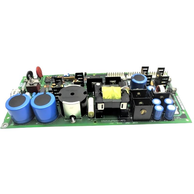
1. Introduction
The GE DS200UPSAG1AGD is a UC200 power supply board associated with the GE Mark V Speedtronic control system. It supports power-related functions within the control assembly and is equipped with three protective fuses, one LED indicator, one reset button, three 9-pin connectors, capacitors, and diagnostic test points.
When this board develops a fault, the symptoms may include abnormal power indications, intermittent operation, controller-related alarms, or failure of associated equipment to operate correctly. However, not every power or control-system alarm indicates a defective DS200UPSAG1AGD. External power conditions, connected boards, wiring, rack connections, and system configuration should also be investigated.
This guide provides a structured approach to identifying possible faults, performing safe inspections, and determining whether the board requires repair or replacement.
2. Product Identification and Main Components
| Item | Description |
|---|---|
| Manufacturer | General Electric (GE) |
| Model | DS200UPSAG1AGD |
| Product type | UC200 Power Supply Board |
| System family | GE Mark V / Speedtronic |
| Functional acronym | UPSA |
| Protective fuses | 3 |
| LED indicator | 1 |
| Reset button | 1 |
| Connectors | 3 × 9-pin connectors |
| Diagnostic features | Test points and onboard components |
Before troubleshooting, confirm the complete part number and revision printed on the installed board. Boards with similar DS200UPSAG1 model numbers may have different revision suffixes or hardware configurations. Do not assume that connector assignments, fuse ratings, or electrical characteristics are identical across all versions.
3. Common Fault Symptoms
3.1 Board LED Does Not Illuminate
An unlit LED may indicate that the board is not receiving the expected power, that an upstream supply or connection is interrupted, or that the board has an internal fault. The LED alone cannot identify the failed component.
Possible causes include:
- Missing or abnormal incoming power.
- Loose or incorrectly seated connectors.
- An open protective fuse.
- A fault in an upstream power distribution circuit.
- Damage to the board’s internal power circuitry.
Check the system power status and external connections first. Electrical measurements should only be performed by qualified personnel using the approved test procedure for the exact hardware revision.
3.2 Intermittent Board Operation
If the control system experiences intermittent power-related alarms or unstable operation, inspect the board and its surrounding installation for possible connection, environmental, or component problems.
Potential causes include loose connectors, damaged cables, contamination, excessive temperature, deteriorated solder joints, or unstable upstream power. A reset may temporarily restore operation, but repeated resets should not be used as a substitute for identifying the underlying fault.
3.3 Protective Fuse Failure
The DS200UPSAG1AGD contains three protective fuses. A blown fuse may interrupt a protected circuit and cause abnormal board behavior or loss of a related function.
A fuse failure should be treated as evidence of an electrical problem, not simply as a component that needs replacement. Possible causes include a short circuit, an overloaded circuit, a defective connected component, or an internal board failure.
Never install a fuse with a higher rating or an unverified specification. The correct fuse type and rating must be confirmed from the applicable GE documentation or the original board markings.
3.4 Control-System Alarms or Abnormal Operation
A fault associated with the power supply board may appear as an alarm elsewhere in the Mark V system. Before replacing the DS200UPSAG1AGD, determine whether the alarm is directly related to its power functions or originates from another board, external supply, or field connection.
Review the alarm sequence, event timestamps, system status, and any related diagnostic indications. Correlating the alarm with the actual operating conditions helps prevent unnecessary board replacement.
3.5 Communication or Connection-Related Problems
Incorrectly seated or misplaced 9-pin connectors can cause abnormal operation in an interconnected control assembly. Damaged cable contacts, loose plugs, or incorrect reconnection after maintenance should be considered during diagnosis.
Do not identify connector functions by appearance alone. Record the existing cable positions and verify each connection against the wiring drawings for the installed revision.
4. Safety Precautions Before Troubleshooting
The DS200UPSAG1AGD is used in an industrial control environment where hazardous electrical energy may be present. Troubleshooting and replacement must be performed by qualified technicians familiar with the GE Mark V system.
- Follow the plant’s lockout/tagout procedure before removing or handling the board.
- Isolate all relevant power sources, including auxiliary supplies where applicable.
- Follow the approved capacitor-discharge procedure and verify the absence of hazardous residual voltage with suitable test equipment. Do not rely on a fixed waiting period alone.
- Use appropriate ESD protection when handling the printed circuit board.
- Do not touch exposed conductors, components, or test points while energized.
- Do not press the reset button or perform live measurements unless the exact procedure explicitly authorizes the action and the technician is qualified to perform it.
- Record the original wiring, connector positions, board revision, and system configuration before disassembly.
5. Step-by-Step Troubleshooting Procedure
Step 1: Confirm the Fault Description
Start by recording the actual symptom instead of immediately assuming that the power supply board has failed.
- Record the alarm message and event time.
- Determine whether the fault is continuous or intermittent.
- Identify which control functions or associated boards are affected.
- Check whether the problem appeared after maintenance, a power interruption, or a system modification.
- Compare the current condition with the system’s previous normal operating state.
Step 2: Inspect the External Power Conditions
Check the relevant upstream power distribution equipment and approved system indications. Look for abnormal supply conditions, tripped protective devices, loose external connections, or signs of overheating.
If the upstream supply is unstable or unavailable, correct that condition before concluding that the DS200UPSAG1AGD is defective. Do not apply assumed voltage limits; use the system drawings and exact equipment specifications.
Step 3: Inspect the Board and Connectors
After the equipment has been safely isolated and verified de-energized, inspect the board for visible damage.
- Look for burned or discolored components.
- Check for cracked solder joints or damaged PCB areas.
- Inspect capacitors for visible swelling, leakage, or physical damage.
- Check connector housings and contacts for contamination or mechanical damage.
- Look for dust, moisture, corrosion, or evidence of overheating.
- Confirm that the board is correctly seated and secured.
Do not clean or repair the board using methods that could damage its coating, contacts, or components. Use an approved electronics maintenance procedure.
Step 4: Check the Three Protective Fuses
Inspect all three fuses according to the approved maintenance procedure. Visual inspection may reveal an obviously damaged fuse, but electrical continuity testing is more reliable when performed with the circuit safely isolated and the fuse tested as specified.
If a fuse is open, investigate the protected circuit and connected equipment before installing a replacement. Use only the exact approved fuse specification. If the replacement fuse opens again, stop repeated replacement attempts and investigate the underlying short circuit or overload.
Step 5: Evaluate the LED Indication
Record whether the board LED is illuminated under the approved operating conditions. Compare the indication with the relevant system documentation and other available diagnostic information.
An illuminated LED should not automatically be interpreted as proof that every board function is healthy. Likewise, an unlit LED does not by itself establish that the board must be replaced. Correlate the indication with power checks, fuse condition, system alarms, and qualified diagnostic measurements.
Step 6: Review the 9-Pin Connector Connections
Inspect the three 9-pin connectors and their associated cables for physical damage, loose connections, or signs of incorrect installation. If a connector has been removed, verify its original position using the cable labels, board markings, and system wiring drawings.
Do not rely on a connector arrangement copied from a different DS200UPSAG1 revision. Exact connector assignments must be confirmed for DS200UPSAG1AGD and the installed system configuration.
Step 7: Perform Approved Electrical Tests
The board includes test points intended to support circuit-level diagnosis. Measurements should be made only by qualified technicians using the correct test equipment, approved procedures, and documented reference values for the exact revision.
Do not apply generic voltage values or assumed test-point assignments from another board. If the required reference values or test procedures are unavailable, stop and obtain the appropriate technical documentation before proceeding.
Step 8: Determine Whether Repair or Replacement Is Required
Consider board repair or replacement when the evidence indicates an internal hardware fault, such as repeated protective fuse failure after external causes have been excluded, visible component damage, or electrical test results outside the approved limits.
If the board passes its documented checks, continue investigating the upstream power supply, connected boards, wiring, and system-level configuration rather than replacing it without evidence.
6. Troubleshooting Reference Table
| Symptom | Possible Cause | Recommended Action |
|---|---|---|
| LED not illuminated | Missing supply, open fuse, connection problem, or internal fault | Check upstream power, connectors, fuses, and approved diagnostic values |
| Intermittent operation | Loose connection, unstable supply, environmental issue, or component deterioration | Review event history and inspect the board and associated wiring |
| Fuse repeatedly opens | Short circuit, overload, defective connected equipment, or internal board damage | Investigate the protected circuit before replacing the fuse again |
| Abnormal system alarms | Power distribution issue, connected-board fault, or board malfunction | Correlate alarms with system status and upstream supply conditions |
| Problem after board replacement | Incorrect revision, connector placement, or installation error | Verify the complete part number, revision, wiring, and seating |
| Visible overheating | Electrical stress, poor connection, or component failure | Isolate the equipment and arrange qualified inspection |
7. Reset Button: When and How to Consider It
The board includes a reset button. A reset may be relevant when an approved diagnostic procedure identifies a recoverable board operating condition. However, resetting the board does not repair damaged components, restore an interrupted supply, or resolve an external short circuit.
Before considering a reset:
- Record the current alarms and diagnostic indications.
- Confirm that the operating procedure permits a reset in the current equipment state.
- Understand the possible effect on connected control functions.
- Ensure that the action is performed by authorized personnel.
- Observe whether the original fault returns after the reset.
If the fault reappears, continue diagnosis instead of repeatedly resetting the board.
8. Repair and Replacement Considerations
8.1 When Board Repair May Be Appropriate
Professional board-level repair may be considered when a specific damaged component or circuit can be identified and the repair can be completed using suitable electronic test equipment and approved workmanship standards.
After repair, the board should undergo appropriate inspection and functional testing before being returned to service. Unverified component substitutions or improvised circuit modifications can introduce additional faults.
8.2 When Replacement Is Recommended
Replacement may be appropriate when the PCB has extensive thermal damage, damaged circuit paths, repeated unexplained fuse failures, or test results that confirm an internal fault that cannot be reliably repaired.
When selecting a replacement, verify:
- Complete model number: DS200UPSAG1AGD.
- Functional and hardware revision compatibility.
- Connector layout and cable arrangement.
- Approved fuse specifications.
- Compatibility with the installed Mark V control configuration.
- Physical condition and evidence of previous repair or damage.
8.3 Post-Replacement Verification
After installation, qualified personnel should verify the board’s seating, connector positions, protective devices, and system configuration. Restore power only under the approved commissioning procedure.
Check the relevant status indications, alarms, and associated control functions. Monitor the system for recurring faults and document the replacement details, revision information, and test results.
9. Preventive Maintenance Recommendations
- Keep the control cabinet clean and within its specified environmental limits.
- Inspect cable routing and connector condition during scheduled maintenance.
- Review recurring power-related alarms instead of treating them as isolated events.
- Check protective fuses using the approved maintenance procedure.
- Maintain records of board part numbers, revisions, repairs, and replacements.
- Use ESD-safe handling and suitable protective packaging for spare boards.
- Keep the correct system drawings and revision-specific technical documentation available.
10. Frequently Asked Questions
What is the GE DS200UPSAG1AGD?
It is a GE UC200 power supply board associated with the Mark V Speedtronic control system. Its functional acronym is UPSA.
How many fuses are installed on the DS200UPSAG1AGD?
The board is commonly identified as having three protective fuses. Their exact ratings and replacement specifications must be verified from the applicable documentation or original board markings.
Does an illuminated LED mean the board is working correctly?
Not necessarily. The LED provides an indication, but it does not independently confirm that every power circuit and board function is operating correctly.
Why does the board keep blowing fuses?
Repeated fuse failure may indicate a short circuit, overload, defective connected equipment, or internal board damage. The underlying cause must be identified before another fuse is installed.
Can the DS200UPSAG1AGD be replaced with another DS200UPSAG1 version?
Do not assume direct interchangeability based only on a similar base model number. Confirm the complete part number, revision, connector arrangement, and system compatibility before replacement.
Can the board be reset without switching off the system?
The board has a reset button, but whether it can be used during operation depends on the approved system procedure and the potential effect on connected equipment. Only authorized technicians should perform this action.
What should be checked first when the board does not operate?
Begin with the fault history, upstream power condition, external connections, fuse condition, and board status indication. Then proceed to revision-specific electrical tests if necessary.
11. Conclusion
Effective troubleshooting of the GE DS200UPSAG1AGD requires a systematic approach that considers the board, its upstream power supply, connected equipment, and the wider Mark V control system. Checking the three protective fuses, LED indication, 9-pin connectors, and diagnostic test points can help narrow down possible fault locations.
However, visual inspection and individual indicators are not sufficient to confirm every internal failure. Accurate diagnosis depends on revision-specific documentation, approved electrical measurements, and qualified maintenance procedures. Correct identification of the board and its system connections is also essential when arranging repair or replacement.
Technical Summary
The GE DS200UPSAG1AGD UC200 Power Supply Board is a Mark V control-system component equipped with three protective fuses, one LED indicator, one reset button, three 9-pin connectors, capacitors, and diagnostic test points. Common troubleshooting areas include power availability, fuse condition, connector integrity, board status indications, and internal circuit condition. Before replacement, verify the complete part number and revision, investigate the cause of any fuse failure, and confirm compatibility with the installed control system.