
NewsNEWCENTER
Featured products



Contact Us
GE DS200TBQCG1ABB Analog I/O Termination Board: Installation, Setup and Commissioning Guide
2026-11-09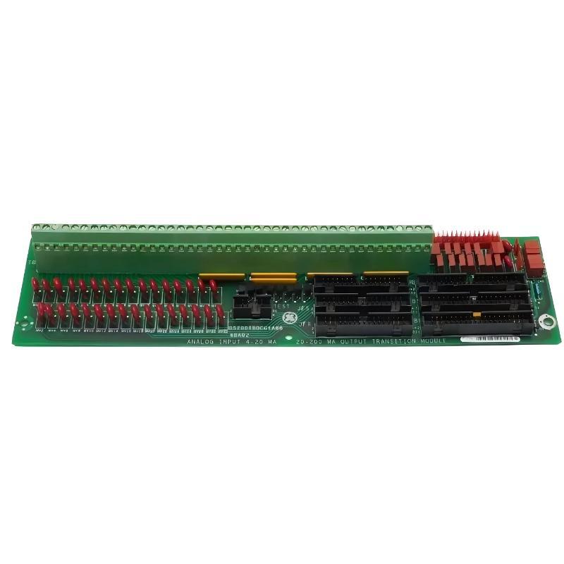
1. Product Overview
The GE DS200TBQCG1ABB is an Analog Input Milliamp I/O Termination Module designed for the GE Mark V Speedtronic turbine control system. It is also identified as an RST Analog Termination Board, with the functional acronym TBQC. The board provides termination and interface connections for analog signals within the turbine control architecture. It serves as an important connection point between field wiring and the associated analog control circuitry. Typical signal applications include milliamp analog inputs and LVDT/R position-related signals. The DS200TBQCG1ABB is not simply a standalone analog signal processing card. It operates as part of the larger Mark V I/O arrangement and works with associated control electronics, including the TCQA interface. Correct installation therefore requires attention to the complete system configuration, field wiring, connector arrangement, and jumper settings. For turbine control maintenance and replacement projects, identifying the exact board revision and installed system position is essential. A visually similar TBQC board should not automatically be treated as interchangeable with the DS200TBQCG1ABB.
2. Technical Specifications
| Parameter | Specification |
|---|---|
| Manufacturer | General Electric (GE) |
| Model | DS200TBQCG1ABB |
| Product Type | Analog Input Milliamp I/O Termination Module |
| Functional Description | RST Analog Termination Board |
| Functional Acronym | TBQC |
| Product Series | GE Mark V Speedtronic |
| Functional Revision 1 | A |
| Functional Revision 2 | B |
| Artwork Revision | B |
| Terminal Blocks | 2 |
| Terminal Capacity | 83 terminals per block |
| 40-Pin Connectors | 3 |
| 34-Pin Connectors | 3 |
| Jumper Configuration | Multiple board-mounted configuration jumpers |
| Associated Control Board | TCQA |
| Typical Signal Types | Milliamp analog signals and LVDT/R position signals |
| PCB Coating | Normal coating |
The terminal capacity and connector arrangement describe the board’s physical interface. They should not be interpreted as a statement that every terminal or connector is used in every Mark V installation. Actual signal assignments depend on the turbine control design and installed configuration.
3. Main Functions of the DS200TBQCG1ABB
3.1 Analog Signal Termination
The primary function of the DS200TBQCG1ABB is to provide termination points for analog field signals. Field instruments used in turbine control applications may measure variables such as pressure, temperature, flow, and other process conditions. The terminal blocks provide organized connection points for field wiring. Proper termination helps maintain signal identification and supports reliable connections between field devices and the control system.
3.2 Milliamp Signal Interface
The board is associated with analog milliamp input and output signal paths in the Mark V architecture. Industrial current-loop signals, including 4–20 mA signals, are commonly used to transmit process measurements from field instruments. The TBQC board provides the relevant termination and interface connections. Signal processing and control functions are performed by the associated system electronics rather than by treating the termination board as an independent measurement controller.
3.3 LVDT/R Position Signal Connections
The DS200TBQCG1ABB also supports LVDT/R-related position signal connections through the Mark V interface arrangement. Position feedback is important in turbine control applications because the control system may need to monitor the position of valves or other mechanical components. The board provides the relevant termination path to associated control electronics.
3.4 Interface with TCQA Control Electronics
The board uses ribbon-cable connections to interface with associated TCQA circuitry. The JBR connector is associated with milliamp input/output signal paths to and from the TCQA board. The JFR connector is associated with LVDT/R position input signals. Other board connections, including JBS/T, JFS/T, and TEST, must be handled according to the applicable system drawings. Their presence does not mean that every connection is required in every installation.
3.5 Jumper-Based Signal Configuration
The board includes multiple jumpers that are associated with signal configuration. Their functions depend on the relevant circuit and installed system design. Configuration jumpers must be treated as part of the original Mark V engineering arrangement. Their positions should be documented before removal or replacement. Never copy jumper settings from another board simply because it has a similar model designation.
4. Preparation Before Installation
Correct preparation reduces installation errors and helps protect the Mark V control system.
4.1 Verify the Board Model
Before installation, check the product label and confirm the complete part number: DS200TBQCG1ABB Also inspect the functional and artwork revision markings. Do not rely solely on the TBQC acronym or the general description of an analog termination board. Confirm that the replacement board is approved for the intended Mark V cabinet, R/S/T core arrangement, and associated TCQA configuration.
4.2 Check the Physical Condition
Inspect the board for:
- Cracked or damaged PCB material.
- Burn marks or signs of overheating.
- Corrosion or contamination.
- Damaged terminal blocks.
- Loose or bent connector pins.
- Missing or damaged jumpers.
- Evidence of unauthorized component replacement.
Pay particular attention to the two terminal blocks and the ribbon-cable connectors. Any physical damage should be evaluated before the board is installed.
4.3 Prepare Installation Records
Before removing an existing board, record its installed configuration. Recommended records include:
- Photographs of the board label and revision markings.
- Photographs of both terminal blocks.
- Field wire labels and terminal numbers.
- Ribbon-cable connector identification.
- All installed jumper positions.
- Associated TCQA board identification.
- Mark V core and cabinet location.
These records help technicians reproduce the original wiring and configuration during replacement.
5. Safety Precautions
The DS200TBQCG1ABB is installed in a turbine control environment. Incorrect wiring or configuration changes can affect process measurements, control functions, and equipment availability. Before beginning installation:
- Follow the site’s approved turbine maintenance procedure.
- Isolate the relevant power sources.
- Apply lockout/tagout requirements.
- Verify that the equipment is de-energized before handling the board or field wiring.
- Allow stored electrical energy to discharge according to system instructions.
- Use suitable ESD protection when handling the PCB.
- Keep loose screws, tools, and metal objects away from electronic assemblies.
- Do not disconnect or reconnect ribbon cables while energized unless an approved procedure explicitly permits it.
Never assume that a termination board is electrically safe to handle simply because it does not function as a standalone power supply. Field wiring and connected circuits may still carry hazardous or damaging electrical energy.
6. DS200TBQCG1ABB Installation Procedure
6.1 Step 1: Isolate the Equipment
Place the affected equipment in the approved maintenance condition. Isolate the relevant control system circuits and field signal sources according to the turbine maintenance procedure. Verify the absence of hazardous voltage before touching terminal connections or removing the board.
6.2 Step 2: Record the Existing Wiring
Document the wiring connected to both terminal blocks. The board has two terminal blocks, commonly identified as TB1 and TB2, with 83 numbered terminals on each block. Record each field wire using its terminal block and terminal number. For example, TB1-20 and TB2-20 must be treated as different connection points. Do not rely on wire color alone. Use the original wiring drawings, cable schedules, and field identification labels.
6.3 Step 3: Record the Jumper Positions
Before removing the original board, photograph and record every installed jumper. The jumper arrangement can affect how milliamp input signals and output circuits are configured. A different jumper position may change the electrical behavior of the associated signal path. Do not remove, reposition, or add jumpers based on assumptions. Use the applicable Mark V documentation and the original approved configuration record to establish the correct arrangement.
6.4 Step 4: Disconnect the Field Wiring and Ribbon Cables
After confirming isolation, disconnect the field wires using the approved procedure. Label each wire before removal. Keep the terminal block identity and individual terminal number associated with each wire. Next, identify and disconnect the ribbon cables. The board has three 40-pin connectors and three 34-pin connectors. Connector identification must be preserved during removal. The principal interface connections include:
| Connector | Documented Function |
|---|---|
| JBR | Associated with milliamp input/output signals to and from the TCQA board |
| JFR | Associated with LVDT/R position input signals to the TCQA board |
| JBS/T | System-dependent connection; verify the applicable drawing |
| JFS/T | System-dependent connection; verify the applicable drawing |
| TEST | Test-related connection; follow the approved system documentation |
Do not infer connector assignments from physical location alone.
6.5 Step 5: Remove the Existing Board
Remove the board’s mounting hardware carefully. Support the PCB during removal to prevent mechanical stress. Keep screws and other small hardware away from adjacent electronic assemblies. A loose metal object can cause an electrical short or mechanical damage. Place the removed board in suitable ESD-protective packaging if it is being retained for inspection or repair.
6.6 Step 6: Install the Replacement Board
Inspect the mounting area and confirm that the replacement board matches the required installation position. Install the DS200TBQCG1ABB carefully and secure it using the approved mounting hardware. Avoid excessive mechanical force. Do not bend the PCB or apply pressure to terminal blocks and connector housings.
6.7 Step 7: Reconnect the Ribbon Cables
Reconnect each ribbon cable according to the labels, photographs, and original system drawings. Before securing a cable, verify:
- Correct connector identification.
- Correct cable orientation.
- Proper alignment of connector contacts.
- Full and secure engagement.
- No twisted or damaged cable conductors.
Do not interchange connectors because their physical appearance seems similar. A wiring or connector error may cause incorrect analog signal routing or loss of feedback.
6.8 Step 8: Reconnect the Field Wiring
Reconnect the field wires to their documented terminal positions. Check the terminal block designation and individual terminal number for every connection. Verify that each wire is secure and that no conductor strands are exposed in a way that could contact adjacent terminals. Where shielded instrumentation cables are used, follow the grounding and shielding arrangement specified in the turbine control drawings.
6.9 Step 9: Verify Jumper Configuration
Compare the replacement board’s jumper positions with the approved configuration record. The correct configuration must be determined from the specific Mark V application. Do not assume that every DS200TBQCG1ABB installation uses identical jumper settings. Any unexplained difference should be resolved before power is restored.
7. Setup and Configuration Considerations
7.1 Milliamp Input Signal Configuration
The board is associated with milliamp analog input circuits. In many industrial control applications, 4–20 mA loops are used to transmit process variables. Before commissioning, confirm:
- The field instrument’s signal type.
- The correct terminal block and terminal number.
- The applicable input channel assignment.
- The corresponding TCQA interface connection.
- The signal reference and grounding arrangement.
- The expected measurement range in the control system.
Do not assume that every terminal is assigned to a 4–20 mA input. Confirm the actual channel allocation from the approved turbine wiring documentation.
7.2 Milliamp Output Configuration
The TBQC board is also associated with milliamp output signal paths. The board’s jumper arrangement may be relevant to output current configuration. Some board documentation describes jumper positions BJ16 and BJ17 as selecting the maximum current range for two milliamp output circuits. Because jumper assignments and board revisions must be verified, technicians should not change these settings without the correct documentation for the installed hardware.
7.3 LVDT/R Signal Configuration
LVDT/R-related position signals are routed through the board’s interface arrangement to the associated TCQA circuitry. Confirm that the correct position feedback wiring is connected to the designated terminals and that the associated control system configuration matches the installed sensor and mechanical equipment. Incorrect wiring or signal assignment may result in inaccurate position feedback or abnormal turbine control behavior.
7.4 Terminal Identification and Signal Records
A complete signal record should include:
| Record Item | Purpose |
|---|---|
| Terminal block ID | Identifies TB1 or TB2 |
| Terminal number | Identifies the exact connection point |
| Field instrument tag | Identifies the connected device |
| Signal type | Identifies the electrical signal arrangement |
| TCQA interface | Identifies the associated control electronics |
| Jumper configuration | Records the approved hardware settings |
| Shielding and grounding | Documents the cable protection arrangement |
Maintaining these records makes future troubleshooting and replacement work more reliable.
8. Commissioning and Functional Testing
Commissioning should confirm that the replacement board has been installed correctly and that the associated analog signal paths operate as intended.
8.1 Initial Visual Inspection
Before restoring power, inspect the complete installation. Check that:
- The board is properly mounted.
- All required connectors are correctly seated.
- Field wires are connected to the documented terminals.
- Terminal screws and connections are secure.
- Jumper positions match the approved configuration.
- No loose hardware or tools remain inside the cabinet.
8.2 Controlled Power Restoration
Restore power according to the approved Mark V startup and maintenance procedure. Observe the system for unexpected alarms or abnormal behavior. If an electrical fault, smoke, overheating, or abnormal odor is detected, stop the procedure and follow the site’s safety requirements.
8.3 Verify Analog Input Signals
Use the approved test procedure to verify the relevant field input channels. For each selected channel:
- Identify the field instrument and corresponding terminal assignment.
- Confirm the signal type and expected operating range.
- Check the field signal using an appropriately rated instrument and approved test method.
- Review the corresponding Mark V control system indication.
- Compare the measured and displayed values with the instrument calibration and system engineering records.
Any discrepancy should be investigated before the associated control function is released for normal operation.
8.4 Verify Milliamp Output Signals
For applicable output circuits, confirm the intended signal behavior using the approved commissioning procedure. Verify the output channel assignment, configured range, receiving device, and associated jumper settings. Do not apply an assumed load or test current without confirming the circuit design and permitted test method.
8.5 Verify LVDT/R Position Feedback
For systems using LVDT/R position feedback, compare the control system indication with the approved position reference or calibration procedure. Confirm that the feedback changes in the expected direction and corresponds to the mechanical position. Any abnormal feedback should be investigated before the associated turbine control function is returned to service.
8.6 Review System Diagnostics
Review Mark V alarms, channel status, and diagnostic information after installation. Confirm that the replacement has not introduced new signal faults and that all affected channels are operating according to the approved control system configuration.
9. System Integration and Application Areas
The DS200TBQCG1ABB is intended for use as part of the GE Mark V Speedtronic turbine control architecture. Typical application areas include:
- Gas Turbine Control: Provides termination and interface connections for selected analog field signals used in turbine monitoring and control.
- Steam Turbine Control: Supports the analog signal wiring arrangement in compatible turbine control cabinets.
- Industrial Power Generation: Helps connect process instrumentation with the associated Mark V analog control circuitry.
- Position Feedback Systems: Supports LVDT/R-related signal connections used in selected turbine applications.
- Plant Instrumentation: Provides organized termination for compatible analog signal circuits.
The board should be selected and installed according to the complete system architecture, not simply by matching the general description of an analog termination board.
10. Maintenance Recommendations
Periodic inspection helps maintain reliable signal connections and reduces the risk of unexpected control system problems. Recommended maintenance activities include:
- Inspect terminal blocks for loose connections and physical damage.
- Check ribbon cables for mechanical wear and damaged contacts.
- Inspect the PCB for corrosion, contamination, or overheating.
- Verify that jumper positions remain consistent with approved records.
- Review recurring analog input and output alarms.
- Compare selected field signal readings with control system indications.
- Keep wiring drawings and board replacement records up to date.
Maintenance intervals should be established according to equipment criticality, operating environment, and the site’s turbine maintenance program.
11. Frequently Asked Questions
What is the GE DS200TBQCG1ABB?
The DS200TBQCG1ABB is a GE Mark V Analog Input Milliamp I/O Termination Module, also known as an RST Analog Termination Board. It provides field signal termination and interface connections within the turbine control system.
Is the DS200TBQCG1ABB a standalone analog input card?
No. It is a termination and interface board rather than a standalone analog signal processing controller. It works with associated Mark V control electronics, including the TCQA board.
How many terminal points does the board have?
The board has two terminal blocks, each containing 83 terminals. Actual terminal usage and signal assignments depend on the specific Mark V system configuration.
What are the main connectors on the DS200TBQCG1ABB?
The board has three 40-pin connectors and three 34-pin connectors. The principal identified interfaces include JBR, JFR, JBS/T, JFS/T, and TEST. Their exact use should be confirmed against the applicable system drawings.
What is the function of the JBR connector?
JBR is associated with milliamp input and output signal paths to and from the TCQA board in the relevant Mark V control cores.
What is the function of the JFR connector?
JFR is associated with LVDT/R position input signals routed to the TCQA board.
Why are jumper settings important?
Jumpers are used for hardware signal configuration. Incorrect settings can affect the behavior of associated milliamp circuits. Always preserve and verify the original approved configuration before replacing the board.
Can another TBQC board replace the DS200TBQCG1ABB?
Not automatically. Replacement compatibility must be verified using the complete part number, functional and artwork revisions, connector arrangement, jumper configuration, associated TCQA hardware, and the receiving Mark V system requirements.
What should be checked after installation?
Check terminal wiring, ribbon-cable connections, jumper positions, analog input indications, applicable output circuits, LVDT/R feedback, and Mark V diagnostic information before returning the affected equipment to service.
12. Conclusion
The GE DS200TBQCG1ABB Analog Input Milliamp I/O Termination Module is an important interface component in the Mark V Speedtronic turbine control system. Its two terminal blocks, multiple ribbon-cable connectors, and configuration jumpers support the termination and routing of selected analog signals. Successful installation requires accurate board identification, careful field wiring documentation, correct connector handling, and preservation of the approved jumper configuration. Commissioning should verify the affected analog input, output, and position feedback paths through the associated Mark V control system. For maintenance teams and industrial automation engineers, following the correct system drawings and hardware revision requirements is essential for achieving reliable operation and avoiding signal configuration errors.
Technical Summary
The GE DS200TBQCG1ABB is an RST Analog Termination Board, also described as an Analog Input Milliamp I/O Termination Module, for the GE Mark V Speedtronic turbine control system. It features two 83-terminal blocks, three 40-pin connectors, three 34-pin connectors, and multiple configuration jumpers. It interfaces with associated TCQA control electronics for milliamp and LVDT/R-related signal paths. Installation and commissioning must follow the exact Mark V wiring drawings, revision requirements, and approved jumper configuration.