
NewsNEWCENTER
Featured products
Contact Us
GE 104X905BA603 Display Panel with Keypad Troubleshooting Guide
2026-10-06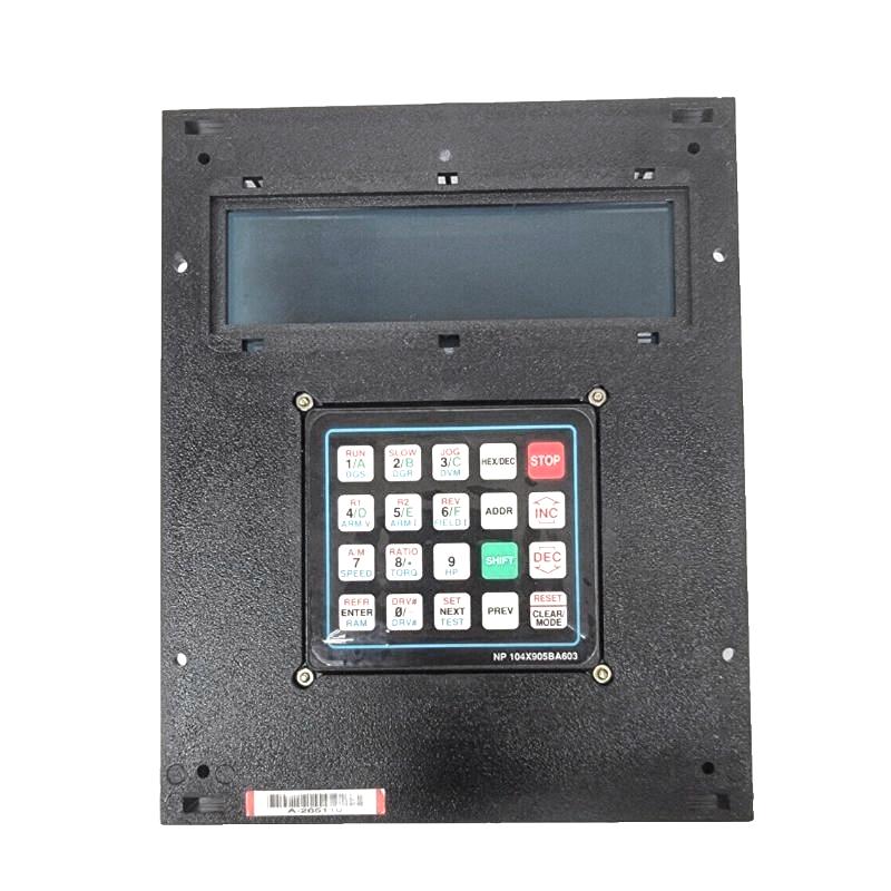
GE 104X905BA603 troubleshooting should begin by separating a display-panel hardware problem from communication, power, cabling, configuration, or controller problems. Symptoms such as a blank display, incorrect information, unresponsive keypad, intermittent operation, or communication errors can originate at different points in the operator-interface system. This GE 104X905BA603 Troubleshooting Guide provides a structured method for fault diagnosis, testing, and repair.
Table of Contents
- GE 104X905BA603 Fault Diagnosis Overview
- GE 104X905BA603 Common Fault Symptoms
- Common Causes of GE 104X905BA603 Faults
- GE 104X905BA603 Troubleshooting Diagnostic Logic
- GE 104X905BA603 Testing and Fault Analysis
- GE 104X905BA603 Repair and Replacement Procedure
- GE 104X905BA603 Field Troubleshooting Case
- GE 104X905BA603 Troubleshooting FAQ
- GE 104X905BA603 Technical Summary
GE 104X905BA603 Display Panel Fault Diagnosis Overview
The GE 104X905BA603 is part of an operator-interface path, so a panel-related fault should be investigated at several levels. The display itself, power supply, communication interface, cables, controller, and application configuration can all affect what the operator sees.
A useful diagnostic strategy is to divide the system into four areas: power, display hardware, communication, and keypad/interface functions.
Power Supply
     |
     v
GE 104X905BA603
     |
 +---+------------------+
 |                      |
 v                      v
Display              Keypad
 |                      |
 +----------+-----------+
            |
            v
Communication Interface
            |
            v
Associated Controller
            |
            v
Control System
This structure makes it easier to identify whether the fault affects the entire panel or only one particular function.
GE 104X905BA603 Common Fault Symptoms
Common symptoms that may lead to troubleshooting of the 104X905BA603 include:
- Display remains blank.
- Display powers up but does not show expected operating information.
- Displayed values appear incorrect or do not update.
- Communication-related indications appear.
- Some keypad functions do not respond.
- Menu navigation becomes intermittent.
- Panel operation changes after cable movement or cabinet maintenance.
- Display resets unexpectedly.
- Operator commands are not recognized by the associated control system.
The same symptom can have different causes. For example, an unresponsive keypad can result from panel hardware, interface communication, configuration, or a system-level condition.
Common Causes of GE 104X905BA603 Faults
Power Supply Problem
An unstable or missing supply can result in a blank display, repeated resets, or intermittent panel operation. The supply path should be checked before assuming internal panel failure.
Loose or Damaged Connection
A loose connector or damaged cable can interrupt power or communication. Intermittent behavior that changes when the cable is disturbed is a useful diagnostic clue.
Communication Problem
If the display operates but information is missing or does not update, the communication path between the panel and associated control equipment should be investigated.
Configuration Problem
An incorrect system configuration can cause valid hardware to display incorrect information or prevent expected operator functions from working.
Keypad Hardware Problem
If the display functions normally but individual keys do not respond, the keypad interface should be tested independently.
Internal Panel Failure
If power, wiring, communication, configuration, and associated controller functions have been verified, the 104X905BA603 itself becomes a stronger candidate for repair or replacement.
GE 104X905BA603 Troubleshooting Diagnostic Logic
Reported Panel Fault
        |
        v
Check Power
        |
   +----+----+
   |         |
 Normal   Abnormal
   |         |
   v         v
Check       Correct
Display     Power Path
   |
   v
Check Communication
   |
   +----+----+
   |         |
 Normal   Abnormal
   |         |
   v         v
Test       Check Cable /
Keypad     Interface
   |
   v
Check Controller Response
   |
   v
Confirm Root Cause
The diagnostic process should always start with the simplest external causes. Replacing the panel before checking its power and communication connections can result in unnecessary hardware replacement.
GE 104X905BA603 Testing and Fault Analysis
Testing should be performed with suitable instruments and according to the plant’s electrical safety procedures. Any keypad function capable of affecting operating equipment should be tested under controlled conditions.
Recommended Diagnostic Sequence
- Record the exact panel symptom.
- Determine whether the display is completely inactive or partially functional.
- Check the electrical supply path.
- Inspect connectors and cables.
- Check communication status.
- Compare panel information with controller information.
- Test keypad functions individually.
- Check whether the fault is continuous or intermittent.
- Review recent maintenance or configuration changes.
- Repeat the test after corrective action.
Illustrative Diagnostic Record
Observed condition:
Display powers up normally

Problem:
Displayed operating information does not update

Controller:
Associated equipment operating normally

Inspection:
Communication connection checked

Diagnostic direction:
Investigate the interface cable and communication path
before replacing the display panel.
The example above illustrates a troubleshooting method and is not a universal electrical specification for the GE 104X905BA603.
GE 104X905BA603 Repair and Replacement Procedure
When troubleshooting indicates that the display panel may require replacement, the work should be performed systematically.
Step 1: Record the Existing Fault
Document the display condition, keypad behavior, communication indications, controller status, and operating conditions associated with the failure.
Step 2: Verify External Causes
Check power, connectors, cables, grounding, communication interfaces, and system configuration before removing the panel.
Step 3: Isolate the Equipment
Apply the approved electrical isolation procedure before disconnecting the display panel.
Step 4: Remove the Existing Panel
Disconnect the identified cables carefully and protect connectors from mechanical damage. Preserve cable identification during removal.
Step 5: Install the Replacement
Install a properly verified 104X905BA603 and reconnect the interfaces according to the applicable system documentation.
Step 6: Perform Controlled Startup
Restore power using the approved procedure and observe the panel initialization sequence.
Step 7: Test Display and Keypad
Verify displayed information, communication status, menu navigation, keypad response, and any permitted operator functions.
Step 8: Reproduce the Original Fault Condition
Where practical, operate the equipment under the same condition that originally caused the problem. This provides stronger evidence that the corrective action has resolved the fault.
GE 104X905BA603 Field Troubleshooting Case
In one representative maintenance case, operators reported that the local display remained active but several values stopped updating. The associated equipment continued to operate, so the maintenance team initially suspected a communication failure.
The engineers compared the information available at the controller with the information shown on the display panel. The controller data remained stable, indicating that the upstream control system was still operating.
The investigation then moved toward the interface connection. A connector was found to be insufficiently secured after previous cabinet work. After correcting the connection, the display resumed normal updating and remained stable during repeated equipment operation.
The case demonstrates an important troubleshooting principle: when the controller continues to operate correctly but the operator panel does not update, the communication path should be checked before replacing the panel.
GE 104X905BA603 Troubleshooting FAQ
What should I check first if the GE 104X905BA603 display is blank?
Start with the power path and connector condition. If the supply is verified, inspect the panel and its associated interface before concluding that the internal display hardware has failed.
What if the display works but the information is incorrect?
Compare the panel information with the associated controller. Then check the communication connection, configuration, and source data to determine where the discrepancy begins.
Why can the keypad stop responding while the display still works?
The display and keypad functions can involve different interface elements. A keypad-specific problem may therefore require separate testing rather than treating the entire panel as failed.
Should I replace the panel when communication is lost?
Not automatically. Check power, cables, connectors, communication interfaces, controller status, and configuration first. If those areas are verified, panel replacement can then be considered.
What should be checked after replacing the 104X905BA603?
Verify display initialization, communication, displayed information, keypad operation, menu navigation, and any permitted control functions. The original fault condition should also be reproduced where practical.
GE 104X905BA603 Technical Summary
The GE 104X905BA603 Display Panel with Keypad provides a local operator interface between personnel and associated industrial control equipment. Troubleshooting requires a complete view of the panel’s power, display, keypad, communication interface, controller, and configuration.
The most reliable GE 104X905BA603 fault-diagnosis method is to isolate the problem by function: verify power first, then display operation, communication, keypad response, and controller interaction. This structured approach can distinguish an actual panel failure from external wiring or system-interface problems and helps reduce unnecessary replacement of serviceable hardware.