
NewsNEWCENTER
Featured products
Contact Us
Foxboro ZCP270 P0926CP Control Processor Troubleshooting and Fault Diagnosis Guide
2026-11-12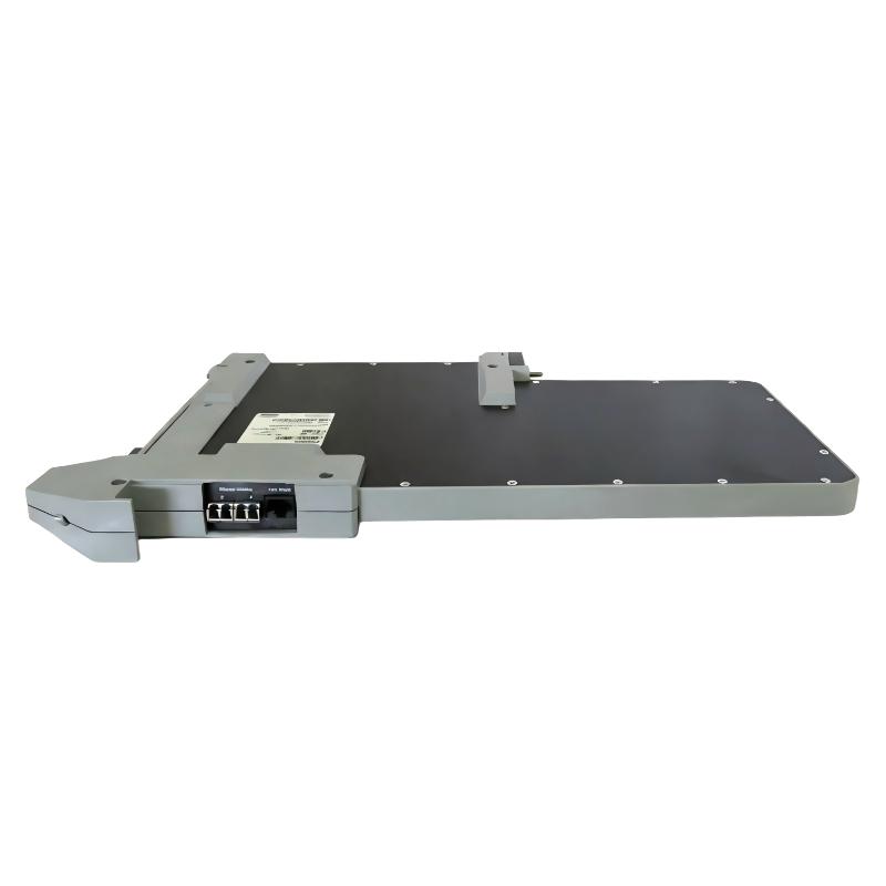
1. Introduction to ZCP270 Fault Diagnosis
The Foxboro ZCP270 P0926CP is a Z-Module Control Processor used in Foxboro I/A Series and compatible Foxboro control system architectures. It performs regulatory, logic, timing, and sequential control while coordinating data exchange with Fieldbus Communication Modules (FCMs), Fieldbus Modules (FBMs), and the control network.
The ZCP270 includes internal startup diagnostics, runtime monitoring, and watchdog functions. Its front-panel indicators provide information about processor health and Ethernet communication activity. These indicators are particularly useful when diagnosing processor startup failures, network interruptions, fieldbus communication problems, and faults in fault-tolerant controller configurations.
This guide explains common ZCP270 fault symptoms, operational LED conditions, communication checks, and practical recovery procedures. Troubleshooting should be performed by qualified Foxboro control system personnel using the approved site maintenance procedure.
2. Common ZCP270 Fault Symptoms
| Fault symptom | Possible cause | Recommended action |
|---|---|---|
| Both operational LEDs are off | Loss of DC power, poor module seating, or a power-bus problem | Check the power supply, rack connection, and module seating |
| Red LED on, green LED off | Startup diagnostic failure or internal hardware fault | Record the condition, review diagnostics, and follow the approved recovery procedure |
| Red and green LEDs remain on | Startup process, software update, configuration issue, or processor fault | Allow the documented startup period and inspect system configuration and diagnostics |
| Red and red/green LED conditions alternate | Possible I/O coprocessor or fieldbus-side diagnostic failure | Check fieldbus connections and associated hardware |
| Control network link LED is off | Disconnected fiber, failed network path, or switch-side problem | Inspect the fiber path and network equipment |
| Fieldbus communication is interrupted | FCM connection problem, fieldbus cable fault, or communication configuration issue | Check the fieldbus network and associated FCM status |
| Fault-tolerant pair does not synchronize | Incorrect interconnecting connector, cabling issue, or configuration mismatch | Inspect the redundant module arrangement and approved connection scheme |
| Unexpected controller restart | Power instability, watchdog event, software issue, or hardware fault | Review event records, power conditions, and processor diagnostics |
3. Understanding the Front-Panel Operational LEDs
The ZCP270 uses separate red and green operational status LEDs. Their combined condition provides an initial indication of processor health. Interpret the LEDs together with system diagnostics rather than treating one indicator as a complete fault diagnosis.
| Red LED | Green LED | Indicated condition |
|---|---|---|
| Off | On | Normal online and functional operating state |
| Off | Off | No power or a condition preventing the status indicators from operating |
| On | Off | Startup diagnostic failure or failed module condition |
| On | On | Startup or software update; if persistent beyond the expected period, investigate a possible processor fault |
During power-up, both LEDs may initially illuminate. The normal operating condition is reached when the red LED turns off and the green LED remains on. A red-and-green condition may persist temporarily during software updates, so do not interrupt the startup process prematurely.
4. Troubleshooting When Both Operational LEDs Are Off
When both operational status LEDs are off, first investigate whether the processor is receiving the required DC power. A dark front panel does not automatically prove that the processor itself is defective.
- Check the power supply status indicators and confirm that the relevant power source is operating normally.
- Inspect the processor’s connection to the mounting structure power bus.
- Review the power distribution wiring and associated connectors.
- Check whether other modules installed in the same mounting structure are operating normally.
- Inspect the processor connector for visible damage, contamination, or bent contacts after safe isolation.
- Where permitted by the maintenance procedure, compare the affected position with a known-good compatible module or approved test arrangement.
If multiple modules in the same structure lose power simultaneously, investigate the shared power supply, distribution connection, and mounting structure before replacing individual processors.
5. Diagnosing a Red LED On and Green LED Off
A red operational LED with the green LED off indicates that the processor has failed to reach its normal operating condition. This can occur when startup diagnostics detect an internal problem.
Recommended checks:
- Record the LED condition and any corresponding system diagnostic messages.
- Check whether the processor is correctly configured in the system management environment.
- Review the power supply and module seating condition.
- Check for visible damage to the module and its connectors.
- Determine whether the fault appeared immediately after installation, a firmware operation, or a configuration change.
- If authorized, perform a controlled processor restart using the approved system management procedure.
If the processor repeatedly returns to the same failed state after the approved recovery steps, the module may have an internal hardware fault. Foxboro maintenance procedures generally favor module replacement over field-level circuit-board repair. Do not attempt component-level repair without an authorized specialist procedure.
6. Troubleshooting When Both Red and Green LEDs Remain On
Both operational LEDs may illuminate during normal startup. If the condition persists, investigate the startup process, configuration, and possible communication problems.
In some cases, a software update can extend the time required for startup. Allow the documented process to complete before taking corrective action.
For a persistent red-and-green condition, check:
- Whether the processor is undergoing a software update or initialization process.
- Whether the correct processor configuration is present in the system management environment.
- Whether the processor is installed in the intended mounting position.
- Whether a fault-tolerant connector is fully seated and secured, if the module belongs to a redundant pair.
- Whether control network A and B fiber connections are correctly assigned.
- Whether fieldbus connections are correctly routed.
- Whether the processor’s diagnostic records indicate a startup or synchronization fault.
In a fault-tolerant arrangement, incorrect cable assignments or a poorly seated interconnecting connector can prevent the two processors from establishing the expected operating relationship. Verify the physical connections against the system drawings.
7. Diagnosing Alternating Red and Red/Green Conditions
If the operational indicators alternate between a red condition and a red/green condition, investigate the I/O coprocessor and fieldbus side of the processor. This pattern may indicate that the main processor has passed initial checks but encounters a problem while loading or validating the I/O-side software.
Follow this diagnostic sequence:
- Check the fieldbus A and B fiber connections.
- Inspect the associated FCM modules and their communication status.
- Verify that the correct fieldbus paths are connected to the intended ports.
- Check whether the same problem exists on a fault-tolerant partner.
- Review the system diagnostic messages for I/O-side or communication-related faults.
- Perform a controlled restart only after confirming that the process and system are in an approved maintenance condition.
If the condition remains after the documented checks, arrange replacement or specialist evaluation of the processor. Repeated resets without identifying the underlying problem may delay diagnosis and affect system availability.
8. Troubleshooting Ethernet Control Network Problems
The ZCP270 communicates with The MESH control network through fiber-optic Ethernet connections. Network communication problems can affect workstation access, controller data exchange, and communication with other system components.
The front-panel control network indicators provide useful information about link and traffic activity:
- Tx indicator: Illuminates when the primary controller transmits data over the corresponding network path.
- Rx/Link indicator: Indicates received communication activity and link status.
- Established link: In normal idle conditions, the Rx/Link indicator is typically illuminated while the Tx indicator is dark until transmission occurs.
- Broken link: If the Rx/Link indicator remains off, investigate the corresponding fiber connection and network path.
When a control network link is unavailable, inspect the following:
- Fiber-optic cable seating and connector condition.
- Correct assignment of network A and network B.
- Fiber routing through the approved splitter/combiner arrangement, where used.
- Network switch port status and configuration.
- Communication status of the other controller and connected workstations.
- Whether the same communication failure affects multiple modules.
Do not swap network A and B cables as an experimental troubleshooting method. In a redundant architecture, incorrect cable assignments can create additional communication or synchronization faults.
9. Troubleshooting Ethernet Fieldbus Communication
The fieldbus Ethernet indicators show activity associated with the processor’s communication paths to the FCM infrastructure. If fieldbus communication is interrupted, determine whether the problem is limited to one path or affects the entire fieldbus network.
Recommended checks include:
- Inspect the fieldbus A and B fiber connections.
- Check the corresponding FCM100E or FCM100Et status.
- Verify that the fieldbus switch and fiber distribution equipment are operating normally.
- Review communication alarms and the availability of connected FBMs.
- Check whether the problem affects one fieldbus segment or multiple segments.
- Confirm that the network configuration matches the installed hardware architecture.
If the processor is online but fieldbus devices are unavailable, investigate the FCM and fieldbus infrastructure before concluding that the ZCP270 has failed.
10. Fault-Tolerant Pair Synchronization Problems
A fault-tolerant ZCP270 arrangement consists of two processor modules operating in parallel. The processors exchange information through a dedicated fault-tolerant connector and use redundant network paths. Their coordinated operation is designed to maintain controller availability when one processor experiences a qualifying hardware failure.
If the pair fails to synchronize or establish the expected primary and shadow relationship, inspect the following:
- Confirm that both processors are compatible and correctly installed in adjacent designated slots.
- Check the dedicated fault-tolerant connector for correct seating and mechanical security.
- Verify that both processors have the intended configuration and compatible software.
- Inspect control network A and B cable assignments.
- Check fieldbus A and B connections.
- Review the system management displays for the current primary and shadow states.
- Confirm that the modules have completed their startup and synchronization procedures.
Do not remove both processors or disturb the redundant connection while the controlled process is operating unless the approved maintenance procedure specifically permits it. The system’s redundancy status and process risk must be evaluated before intervention.
11. Reset and Recovery Procedures
The ZCP270 provides a reset button that can restart the processor. However, resetting should not be the first response to every alarm. A restart may interrupt control functions or change the operating state of a non-redundant controller.
Before performing a reset:
- Check the processor’s current online or primary/standby state.
- Confirm that the controlled process is in an approved condition.
- Record the existing alarms, LED conditions, and diagnostic messages.
- Check whether the fault-tolerant partner is healthy and available, if applicable.
- Obtain authorization from the responsible operations and control system personnel.
Where possible, use the approved system management displays to perform a controlled restart. Use the physical reset button only when the applicable procedure authorizes it. After restarting, verify that the processor returns to its normal operational LED condition, communication links are restored, and the correct application is running.
12. When to Replace the ZCP270 P0926CP
Replacement may be appropriate when the processor repeatedly fails startup diagnostics, cannot maintain normal operation, or continues to show hardware-related faults after power, configuration, and communication issues have been excluded.
Before replacement, confirm:
- The exact processor catalog number and hardware revision.
- The compatibility of the replacement with the installed system platform.
- The required software and firmware revision.
- The approved application and configuration backup.
- The system’s redundancy status and the permitted replacement sequence.
- The correct mounting position and associated connector arrangement.
After installation, verify processor recognition, control network communication, fieldbus communication, and application status. In a fault-tolerant arrangement, confirm that the replacement module successfully establishes the required relationship with its partner before returning the system to normal service.
13. Preventive Maintenance Recommendations
- Review processor status and system diagnostic records during scheduled maintenance.
- Keep control network and fieldbus fiber connections clean, secure, and correctly identified.
- Maintain accurate records of processor revisions, software versions, and configuration changes.
- Inspect cabinet power distribution and environmental conditions.
- Maintain verified backups of the control application and relevant system configuration.
- Document fault-tolerant primary and shadow status during maintenance activities.
- Use approved replacement procedures and avoid unauthorized firmware or configuration changes.
- Investigate recurring communication alarms instead of relying on repeated processor resets.
The ZCP270 performs internal startup and runtime diagnostics. Routine manual diagnostic execution is not normally required; maintenance personnel should focus on reviewing system status and responding to detected faults.
14. Technical FAQs
1. What does the Foxboro ZCP270 P0926CP do?
It performs regulatory, logic, timing, and sequential control in compatible Foxboro control systems. It also coordinates data acquisition and communication with connected FCM and FBM hardware.
2. What does a green operational LED with the red LED off indicate?
This is the normal online and functional operating condition of the ZCP270.
3. What does it mean when both operational LEDs are off?
This generally indicates a loss of DC power or a condition preventing the status indicators from operating. Check the power supply, mounting structure, and module connection before replacing the processor.
4. Why are both red and green operational LEDs illuminated?
This can occur during startup or software updates. If the condition persists beyond the expected startup period, check configuration, connections, synchronization, and diagnostic records.
5. What does an alternating red and red/green LED condition indicate?
It can indicate a problem on the I/O coprocessor or fieldbus side. Inspect the fieldbus connections, associated FCM hardware, and system diagnostics.
6. How can I identify a control network fiber fault?
Check the relevant control network Rx/Link indicator and inspect the corresponding fiber path, splitter/combiner arrangement, and network switch port.
7. Why might a fault-tolerant ZCP270 pair fail to synchronize?
Possible causes include an incorrectly seated fault-tolerant connector, incompatible configuration, incorrect fiber assignments, or communication problems between the modules.
8. Can I reset the ZCP270 while the process is running?
Do not reset it without authorization. First evaluate the process condition, controller role, and redundancy status. Follow the approved site procedure for any restart.
9. Does the ZCP270 require routine manual diagnostic testing?
The processor performs internal startup and runtime diagnostics. Scheduled manual execution of these diagnostics is not normally required, although system status and fault records should be reviewed.
10. When should the ZCP270 be replaced?
Replacement should be considered when persistent hardware-related faults remain after power, configuration, connector, and network problems have been ruled out.
Technical Summary
The Foxboro ZCP270 P0926CP Control Processor includes internal diagnostics and front-panel indicators that help identify power, processor, control network, and fieldbus problems. Effective troubleshooting begins by interpreting the red and green operational LEDs, checking DC power, and reviewing the control network and fieldbus communication paths.
For fault-tolerant installations, the dedicated interconnecting connector, adjacent module positions, and correct redundant network cabling are essential. Before resetting or replacing the processor, record diagnostic information, confirm the system’s operating condition, and follow the approved maintenance procedure. These steps help distinguish a processor hardware fault from a power, configuration, or communication problem.