
NewsNEWCENTER
Featured products
Contact Us
Foxboro ZCP270 P0926CP Control Processor Installation and Commissioning Guide
2026-11-12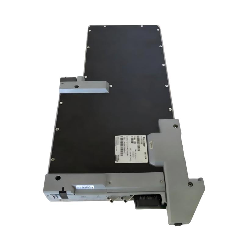
1. Product Overview
The Foxboro ZCP270 P0926CP is identified as a control processor used in industrial process automation systems. As a controller component, it participates in executing control strategies and coordinating communication with associated system hardware. Its role in a process control environment makes correct identification, compatibility checking, installation, and commissioning essential.
Before installing or replacing a ZCP270, maintenance personnel should confirm the complete catalog number, hardware revision, system platform, and applicable engineering documentation. Processor modules that look similar may belong to different system generations or have different firmware and backplane requirements.
2. Pre-Installation Checks
Prepare the installation area and verify the replacement requirements before removing an existing processor.
- Confirm the module label reads ZCP270 and the catalog number is P0926CP.
- Record the hardware revision and any additional identification printed on the module.
- Confirm that the target controller rack or system chassis is designed to accept this exact processor.
- Check the system configuration, firmware requirements, and supported engineering software version.
- Back up the current control application, configuration, communication settings, and relevant diagnostic records.
- Review the approved system drawings to identify power, grounding, network, and rack connections.
- Inspect the module for damaged connectors, cracked housing, corrosion, or signs of overheating.
3. Safety and Handling Requirements
Control processors are part of systems that may directly affect machinery and industrial processes. Installation must be performed by qualified personnel under the site’s maintenance and process-safety procedures.
- Obtain the required maintenance authorization and coordinate with the control-room or operations team.
- Place the controlled process or equipment in an approved safe state before removing a processor.
- Apply lockout/tagout where required and isolate the relevant electrical supplies.
- Allow stored electrical energy to discharge according to the equipment manufacturer’s procedure, then verify the safe condition.
- Use an ESD wrist strap and suitable antistatic handling practices.
- Hold the module by its edges and avoid touching connector contacts or circuit components.
- Never force the module into a rack or connector position.
Do not assume that the processor is hot-swappable. Live insertion or removal is permissible only when the exact system documentation explicitly supports it and the site’s approved procedure authorizes the operation.
4. Installation Procedure
Step 1: Verify the installation location
Identify the designated processor position using the system rack layout and engineering drawings. Confirm the slot assignment and module orientation before handling the hardware. Do not select a slot based only on the physical appearance of another installed module.
Step 2: Inspect the rack and connectors
Check the receiving connector for bent contacts, foreign material, or mechanical damage. Inspect the module guide rails and retention hardware. If the rack connector is damaged, stop the installation and arrange an appropriate repair.
Step 3: Prepare the processor
Confirm that the ZCP270 P0926CP is the approved replacement for the target application. Compare its revision and identification information with the existing module or the approved spare-parts record. Check whether any system-specific configuration or firmware preparation is required before installation.
Step 4: Insert the module
Align the processor with the designated guides and connector. Insert it evenly using the manufacturer’s specified method. Secure the retaining mechanism, if fitted, without applying excessive force. Confirm that the module is fully seated and mechanically secure.
Step 5: Reconnect associated interfaces
Where the installation requires external communication or auxiliary connections, reconnect each cable according to the approved wiring and network drawings. Verify connector identification and cable routing rather than relying on memory or physical similarity.
Step 6: Complete a physical inspection
Check that the processor is correctly seated, retention hardware is secured, and all required connections are restored. Make sure that no tools, loose hardware, or foreign objects remain inside the cabinet.
5. Configuration and System Integration
A replacement processor may require configuration verification before it can operate correctly in the existing control system. The exact configuration method depends on the Foxboro system platform and installed software revision.
- Hardware identification: Confirm that the engineering configuration recognizes the installed processor as the intended hardware type.
- Firmware compatibility: Verify that the processor firmware is supported by the system software and other installed modules.
- Application configuration: Confirm that the correct control strategy and approved configuration are assigned to the processor.
- Communication setup: Check the configured communication interfaces, network identity, and associated system connections against the project documentation.
- Redundancy arrangements: If the installation belongs to a redundant controller arrangement, verify the designated primary and standby roles and the approved synchronization procedure.
- System consistency: Review module status, configuration consistency, and any reported hardware or communication alarms.
Do not invent or copy network addresses, switch positions, firmware images, or configuration parameters from a different processor. Use the exact system drawings and revision-specific engineering instructions.
6. Power-Up and Initial Commissioning
After installation and configuration checks are complete, restore power according to the approved startup sequence. Coordinate with operations before enabling control functions or returning the process to automatic operation.
- Confirm that all installation checks have been completed and signed off.
- Verify that the cabinet power supply and grounding arrangements are correct.
- Restore power using the site’s approved sequence.
- Observe the processor’s status indicators and record their behavior.
- Check the engineering workstation for module recognition and diagnostic messages.
- Verify communication with the expected system components.
- Confirm that the correct application and configuration are present.
- Perform approved control-loop, interlock, and I/O verification tests.
- Obtain operations approval before returning the controlled equipment to normal service.
7. Commissioning Acceptance Checklist
| Inspection item | Acceptance requirement |
|---|---|
| Product identification | ZCP270 P0926CP and hardware revision verified |
| System compatibility | Rack, platform, firmware, and software compatibility confirmed |
| Mechanical installation | Module fully seated and secured |
| Electrical condition | Power and grounding checked against approved drawings |
| Configuration | Correct processor and application configuration recognized |
| Communication | Required system connections operate normally |
| Diagnostics | No unresolved processor or system faults |
| Functional testing | Approved control and I/O checks completed |
| Documentation | Replacement and commissioning records updated |
8. Maintenance Recommendations
Reliable processor operation depends on more than the module itself. Maintain the surrounding control cabinet, power distribution, grounding, cooling, and communication infrastructure.
- Keep an up-to-date backup of the approved control application and configuration.
- Record processor catalog numbers, revisions, firmware versions, and replacement history.
- Inspect cabinet ventilation and environmental conditions during scheduled maintenance.
- Check power supply and grounding conditions when unexplained processor resets occur.
- Review diagnostic logs and investigate recurring communication or hardware alarms.
- Store spare processors in suitable antistatic packaging and controlled storage conditions.
- Use only approved replacement parts and documented firmware or configuration procedures.
9. Technical FAQs
1. What is the Foxboro ZCP270 P0926CP?
It is identified as a Foxboro control processor for industrial process automation applications. Its exact system role and supported platform should be confirmed from the module identification and applicable system documentation.
2. Can the ZCP270 P0926CP be installed in any Foxboro rack?
No. The receiving rack or chassis must be specifically compatible with the processor. Verify the system platform, slot assignment, and hardware revision before installation.
3. Should the system be powered down before replacing the processor?
Follow the exact system maintenance procedure. Unless the applicable documentation explicitly confirms supported live replacement and the site authorizes it, isolate the equipment before removing or inserting the module.
4. Does a replacement processor automatically contain the original control program?
Do not assume so. Confirm the application and configuration requirements, and restore only an approved, verified backup using the correct engineering procedure.
5. What should be checked before commissioning?
Verify the module identity, hardware revision, rack compatibility, firmware requirements, application configuration, power arrangements, and communication connections.
6. Why might a newly installed processor fail to communicate?
Possible causes include incompatible firmware, incorrect configuration, network connection problems, incorrect addressing, or a fault in an associated system component. Check diagnostics and approved network drawings.
7. Can firmware from another Foxboro processor be used?
Not without confirming compatibility. Firmware must match the exact processor model, hardware revision, and system software requirements.
8. What should I do if the processor reports a fault after startup?
Record the exact status indication and diagnostic message. Check power, seating, compatibility, configuration, and communication conditions before deciding whether the processor requires replacement.
9. Is the ZCP270 P0926CP suitable for redundant control systems?
Redundancy support must be confirmed for the exact system architecture and processor revision. Do not assume that a processor supports a particular redundancy arrangement without checking the system design.
10. What information should be recorded after replacement?
Record the processor catalog number, hardware revision, firmware version, rack position, application revision, diagnostic results, test results, and commissioning approval.
Technical Summary
The Foxboro ZCP270 P0926CP Control Processor is an industrial automation component that requires careful compatibility verification and controlled commissioning. Before installation, confirm the processor identity, system platform, hardware revision, firmware requirements, and approved application backup. During commissioning, check mechanical seating, power, communication, configuration recognition, and system diagnostics.
Because exact rack compatibility, connector assignments, firmware requirements, and operating parameters must be established from the applicable Foxboro documentation, these details should not be inferred from the model number alone. A revision-controlled installation procedure and verified application backup are essential for a reliable replacement.