

ProductPRODUCT
Featured products
Contact Us


- Bently Nevada
- 3500/93-05-00-02-00
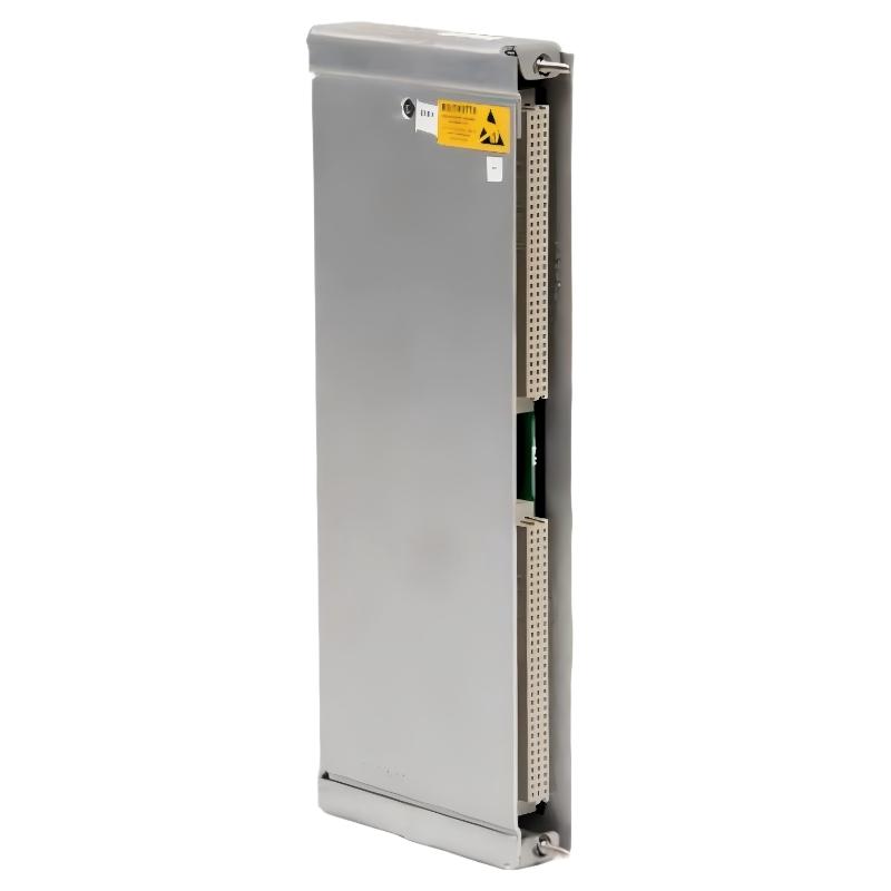
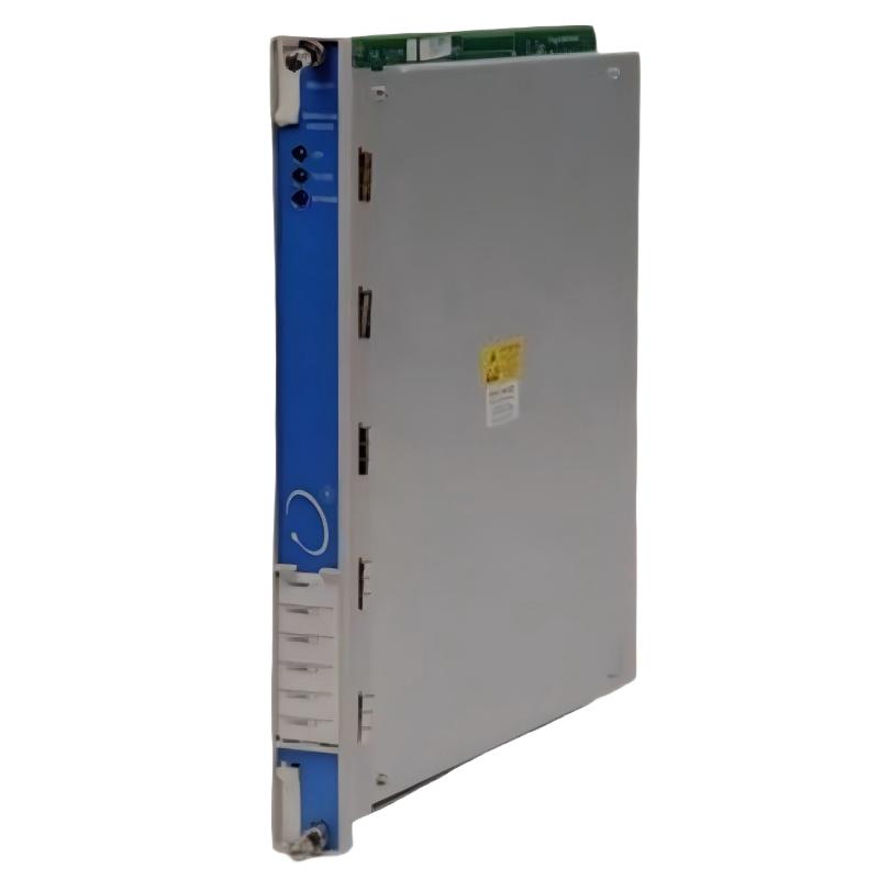
- Display Interface I/O Module
- USA
- 203.2 × 412.8 × 31.2 mm
- 2.1kg
- Xiamen, China
- New & In Stock
- T/T, PayPal, Western Union
- 1 Year
- 1-3 Working Days
- DHL, UPS, TNT, FedEx and EMS.
- 24-Hour Service
- COO
- 2
Our advantage

Global Logistics
We have a 10-year logistics and express cooperation agreement, so our products can be shipped to any place in the world.

Brand new and original
Our products are imported in bulk from the place of origin. Because of the cooperative relationship, our products are all original and 100% new.

24-hour service
We provide 7*24 hours service to our customers. We will be there whenever you need us.

Price advantage
All our products are priced very favorably because we have our own warehouse and supply.
| Company Information | |||
| [email protected] | |||
| Mobile | +8615980777398 | ||
| +8615980777398 | |||
| 15980777398 |
Bently Nevada 3500/93-05-00-02-00 System Display — Product Description, Technical Specifications, Applications and Related Models
1. Product Introduction
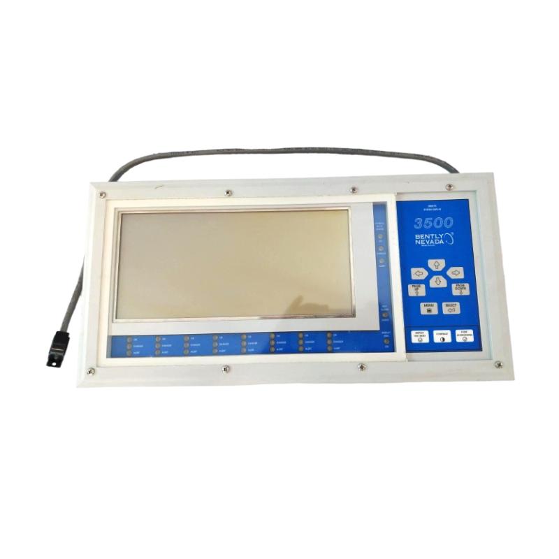
The Bently Nevada 3500/93-05-00-02-00 is a configured 3500 System Display designed to provide local visual access to machinery monitoring and protection information held within a compatible 3500 rack. The model belongs to the 3500 Machinery Monitoring and Protection System and is intended for industrial facilities that need operators and maintenance personnel to review equipment condition, alarm information, and system status directly from a dedicated display.
The 3500/93 display is more than a general-purpose screen. It is part of a purpose-designed interface arrangement that works with the compatible Display Interface Module (DIM), I/O hardware, and the 3500 rack. The system can present supported channel values, monitor information, relay status, Keyphasor information, tachometer data, system events, and alarm event lists, depending on the installed modules and configuration.
The specified ordering code is important because it describes the mounting arrangement and accessory requirements of the display system. In 3500/93-05-00-02-00, the 05 mounting option identifies a back-lighted system face-mount configuration. This arrangement is designed to mount over the front of a compatible full-size 3500 rack, with the Display Interface Module installed in the designated rack position. The 00 cable option indicates that no separate cable is specified in the ordering configuration, the 02 external power-supply option specifies a 230 V AC supply, and the final 00 indicates no additional agency approval option in this ordering format.
The backlighted display is useful when the screen must remain readable under varying ambient-light conditions. The external power-supply requirement is an important part of this configuration and should be considered during installation and replacement planning.
The 3500/93 display is intended to make monitoring information easier to access during normal plant operation, equipment start-up, alarm investigation, maintenance, and troubleshooting. It does not replace the monitoring modules that process sensor signals or the protective logic configured in the rack. Instead, it provides a dedicated visual interface to information generated by the wider machinery monitoring system.
2. Detailed Technical Parameters
The table below summarizes the principal characteristics of the 3500/93-05-00-02-00 System Display. Dimensions and weights are provided separately for the display unit and Display Interface Module because these are distinct physical components within the overall arrangement.
| Parameter | Specification |
|---|---|
| Model | 3500/93-05-00-02-00 |
| Brand | Bently Nevada |
| Product name | 3500 System Display |
| Product category | Industrial machinery monitoring display system |
| Product series | 3500 Machinery Monitoring and Protection System |
| Display family | 3500/93 |
| Mounting option | 05 — back-lighted system face mount |
| Mounting arrangement | Installed over the front panel of a compatible full-size 3500 rack |
| Display Interface Module (DIM) | Required; installed in the designated rack position |
| I/O module | Included under the applicable mounting option |
| Cable option | 00 — no separate cable specified in the ordering configuration |
| External power-supply option | 02 — 230 V AC |
| Agency approval option | 00 — no additional agency approval option specified |
| Display technology | Back-lighted LCD display |
| Display resolution | 640 × 200 dots |
| Display format | Text and graphical information |
| Main display functions | Presents supported monitoring values, channel status, alarm events, and system events |
| Available data categories | Channel, monitor, relay, Keyphasor, tachometer, and system-event information, subject to rack configuration |
| Configuration software | Compatible 3500 Rack Configuration Software |
| Communication arrangement | Display communicates with the compatible Display Interface Module through the designated interface and cable arrangement |
| Main Display Interface Module dimensions (H × W × D) | Approximately 241.3 × 24.4 × 241.8 mm |
| Main Display Interface Module weight | Approximately 0.82 kg |
| Display Interface I/O Module dimensions (H × W × D) | Approximately 241.3 × 24.4 × 99.1 mm |
| Display Interface I/O Module weight | Approximately 0.38 kg |
| Display unit dimensions (H × W × D) | Approximately 203.2 × 412.8 × 31.2 mm |
| Display unit weight | Approximately 2.1 kg |
| Rack space requirement | One full-height front slot for the Display Interface Module and one full-height rear slot for the I/O module |
| External power input | 230 V AC for the specified external power-supply option |
| Operating temperature | Depends on the component and installation; verify the display-unit and interface-module limits separately |
| Storage temperature | Depends on the component revision; verify the applicable technical documentation |
| Relative humidity | Up to 95%, non-condensing, for applicable interface hardware |
| Installation environment | Compatible industrial rack or control-panel environment |
| Intended operating mode | Continuous visual presentation of supported machinery monitoring information |
| Compatibility requirement | Compatible 3500 rack, Display Interface Module, I/O module, display unit, power supply, and configuration |
Physical specification note: The display unit measures approximately 203.2 × 412.8 × 31.2 mm and weighs approximately 2.1 kg. The Display Interface Module and I/O module are separate components with their own dimensions and weights. These values should not be confused with the shipping weight of the complete display arrangement, which depends on the supplied hardware, power supply, mounting parts, and packaging.
3. Product Applications
3.1 Local Machinery Monitoring
The primary application of the 3500/93 System Display is to provide a direct view of machinery monitoring information at the equipment rack or a nearby operator position. In a typical installation, sensors measure machinery parameters, monitoring modules process the signals, and the display system presents supported information in a form that operators can readily review.
The back-lighted display is particularly useful in industrial environments where lighting conditions vary or where operators need to read the screen inside a control cabinet. Its face-mount configuration places the display directly at the front of a compatible rack, making routine checks convenient.
3.2 Alarm and Event Monitoring
Machinery protection systems can generate alarms when monitored values reach configured thresholds or when a module reports an abnormal condition. The 3500/93 can display available alarm and system event information, helping operators identify reported conditions and review the system’s current status.
This is useful during equipment start-up, shutdown, changes in operating load, and investigation of unexpected machinery behavior. The display provides access to the information generated by the rack; alarm limits and protective actions remain functions of the configured monitoring and protection modules.
3.3 Turbine and Generator Applications
Turbines and generators are critical assets in power generation and other process industries. Their condition may be assessed through parameters such as vibration, shaft position, rotational speed, and other measurements supported by the installed monitoring modules.
When integrated with a compatible 3500 rack, the 3500/93 can present available measurements and status information on a dedicated display. Operators can review the displayed data during routine operation and use it as part of their response to alarms or abnormal conditions.
3.4 Compressor and Pump Monitoring
Large compressors and pumps are common in oil and gas processing, petrochemical production, power plants, and water-treatment facilities. Unplanned machinery problems can disrupt production and increase maintenance requirements.
The 3500/93 display allows personnel to view supported monitoring information close to the rack. This can help technicians check channel status, review available alarm information, and determine whether further investigation is required.
3.5 Oil and Gas Processing Facilities
Oil and gas plants often have multiple machinery trains distributed across process units, compressor stations, and utility areas. A dedicated machinery display provides a practical point of access to monitoring information without requiring every operator to open a separate engineering workstation.
The 3500/93 is suitable for compatible installations where local visual access is required. The specified back-lighted face-mount configuration is especially relevant when the display is intended to sit directly over the rack front panel.
The external 230 V AC power-supply requirement must be included in the installation plan. Electrical supply, mounting, grounding, cable routing, and environmental conditions should be checked before the display is placed into service.
3.6 Chemical and Petrochemical Production
Chemical and petrochemical facilities use rotating equipment to maintain process circulation, compression, cooling, and material transfer. Machinery condition monitoring supports operational awareness and maintenance planning.
The 3500/93 can display supported rack information from compatible monitoring modules, helping personnel review equipment status during normal operation and maintenance. It provides a visual interface to the monitoring system rather than a separate measurement function.
3.7 Power Generation and Utility Systems
Power generation facilities use a range of large rotating machines and auxiliary equipment. Operators and maintenance teams may need access to machinery status during inspections, commissioning, fault investigation, and planned shutdowns.
The 3500/93 can serve as a dedicated display point for available rack information. The face-mount design is convenient when the rack is installed in a location where operators need to view the information directly at the equipment.
3.8 Industrial Maintenance and Commissioning
During commissioning, technicians need to confirm that modules are installed correctly, expected measurements are available, and the monitoring rack reports the appropriate status. During maintenance, they may need to review alarm records or check whether a reported issue affects a particular channel or module.
The 3500/93 helps make this information accessible through its display interface. It can reduce dependence on a separate computer for routine visual checks, although detailed configuration, diagnostics, and system maintenance may still require compatible software and test procedures.
3.9 Control Room and Machinery Room Installations
The 3500/93 family supports different mounting configurations depending on the selected ordering option. The 05 configuration is specifically associated with a back-lighted system face-mount arrangement.
This configuration is appropriate when the display is intended to be mounted directly on the front of a compatible full-size rack. It should not be assumed to be interchangeable with panel-mount, 19-inch EIA rack-mount, or independent-mount versions because those options may require different hardware, cabling, and power arrangements.
4. Main Product Advantages
4.1 Direct Access to Monitoring Information
The 3500/93 provides a dedicated visual interface to information available from the 3500 rack. Operators can review supported monitoring values and system status at the equipment rather than relying entirely on a separate computer.
This is valuable in facilities where quick access to machinery condition information is part of routine operating and maintenance work.
4.2 Back-Lighted Display for Better Readability
The 05 configuration specifies a back-lighted system display. The backlight improves screen visibility where ambient lighting is limited or inconsistent.
This can be useful in machinery rooms, industrial cabinets, and other installations where a non-backlighted display may be harder to read. The back-lighted option also explains why the specified configuration requires an external power supply.
4.3 Face-Mount Installation
The face-mount configuration places the display directly over the front panel of a compatible full-size 3500 rack. This provides convenient access to the screen without requiring a separate display enclosure or remote mounting location.
The selected configuration requires the Display Interface Module to be installed in the designated rack position. Installation must follow the rack and display system requirements to ensure the display does not obstruct necessary access or interfere with other rack functions.
4.4 Presentation of Alarm and Event Information
The display system can present available alarm event lists and system event information. This helps operators review reported conditions and supports the initial stages of troubleshooting.
The display is not a replacement for a detailed diagnostic system, but it provides a practical view of information generated by the installed monitoring modules.
4.5 Visibility Across Multiple Monitoring Functions
Depending on the installed rack modules and configuration, the 3500/93 can display information related to channels, monitors, relay modules, Keyphasor modules, tachometers, and system events.
This makes it useful in a monitoring system containing different types of machinery measurements. The actual information available on the screen depends on the modules installed and the system configuration.
4.6 Integration with the 3500 Platform
The 3500/93 is designed for use with the 3500 machinery monitoring and protection architecture. Its dedicated interface arrangement helps maintain compatibility between the rack and the display system.
This is particularly useful for facilities that already use the 3500 platform and want local visual access to information without introducing an unrelated display interface.
4.7 Clear Separation of System Functions
The display provides visual access to monitoring information, while sensors and monitoring modules perform the actual measurement and processing functions. Protective responses are handled by the configured machinery protection system.
This separation makes the system easier to understand and maintain. A display issue does not automatically mean the monitoring channels themselves have failed, although the actual condition must be checked using the rack status and appropriate diagnostics.
4.8 Practical for Routine Inspections
A dedicated display can make routine inspections more efficient by giving technicians a consistent place to review system status and available measurements.
During maintenance rounds, operators can use the display to check the current condition reported by the rack and determine whether further inspection or investigation is required.
4.9 Supports a Structured Installation
The model’s ordering code identifies a specific mounting arrangement and associated accessory configuration. This helps system designers select a display arrangement that suits the intended installation.
For the 3500/93-05-00-02-00 configuration, the main considerations are the back-lighted face-mount arrangement, the 230 V AC external power supply, and the requirements for the associated interface and I/O hardware.
4.10 Suitable for Industrial Monitoring Applications
When installed within its specified operating limits, the display system can serve as part of a continuous industrial machinery monitoring installation.
Reliable operation depends on the complete installation, including the rack, display interface, power supply, wiring, mounting, and configuration. The display should therefore be evaluated as part of the system rather than as an isolated screen.
5. Brand and Product Series
Brand: Bently Nevada
Bently Nevada is the brand associated with the 3500 machinery monitoring and protection product family. Its portfolio includes rack-based monitoring equipment, vibration and position monitoring modules, proximity measurement systems, speed-reference modules, relay modules, communication interfaces, and display accessories.
These products are used in industrial environments where rotating machinery condition must be monitored and presented to operating or maintenance personnel.
The 3500/93 is a display product within this portfolio. It provides a visual interface to information available from a compatible rack rather than directly measuring vibration, position, or rotational speed.
Product Series: 3500 Machinery Monitoring and Protection System
The 3500 series is a modular rack-based platform designed for machinery monitoring and protection applications. A typical installation includes a rack, power supplies, a rack interface, monitoring modules, associated I/O modules, and optional communication, relay, and display hardware.
Each component has a defined function:
-
Monitoring modules process supported sensor signals and provide monitoring information.
-
Rack interface modules provide system-level communication and interface functions.
-
Relay modules provide configured relay outputs.
-
Communication gateways transfer supported rack data to compatible external systems.
-
Display systems present available monitoring information to operators.
The 3500/93 belongs to the display category. It complements the monitoring and protection modules by making their supported information easier to view.
Role of the 3500/93-05-00-02-00 in the Series
The 3500/93-05-00-02-00 is configured for a back-lighted system face-mount installation. It is intended for a compatible full-size 3500 rack and uses the designated Display Interface Module and I/O arrangement.
Its primary function is visual presentation. It should not be confused with the 3500/92 communication gateway, which is designed for data communication, or with measurement modules such as the 3500/42M, which process designated machinery-monitoring signals.
6. Ordering Code Interpretation
The complete ordering code provides important information about how the display system is configured.
| Code segment | Meaning |
|---|---|
| 3500/93 | 3500 System Display family |
| 05 | Back-lighted system face-mount configuration |
| 00 | No separate cable specified in the ordering configuration |
| 02 | 230 V AC external power-supply option |
| 00 | No additional agency approval option specified |
The mounting option 05 is especially important. It identifies a back-lighted face-mount configuration, with the Display Interface Module installed in the designated rack position and the I/O module included under this option.
The 02 power-supply code specifies a 230 V AC external power supply. The final 00 does not mean that the product has every possible industrial certification; it indicates that no additional agency approval option is selected in this ordering format.
Before ordering a replacement, compare the full code with the existing unit’s nameplate and installation records. A display with a similar family number may have a different mounting style, cable arrangement, backlight configuration, or power requirement.
7. Five Related Models in the Same Series or Application
The following models are related to the 3500/93 display system or serve complementary functions in the same machinery monitoring architecture. They may be relevant when maintaining a display installation, replacing associated hardware, or expanding the rack.
Dimensions and weights are approximate references. Where a model is supplied in different configurations, the actual physical specification should be verified against the complete part number.
Dimensions are in millimeters (H × W × D). Weight is in kilograms (kg).
| Model | Product type | Main parameters and function | Dimensions | Weight (kg) |
|---|---|---|---|---|
| 3500/93-02-00-00-00 | System Display | Standard 19-inch EIA rack-mount display configuration; non-backlighted option | Display unit: approx. 203.2 × 412.8 × 31.2 mm | Approx. 2.1 for display unit |
| 3500/93-06-00-02-00 | System Display | Back-lighted 19-inch EIA rack-mount configuration; 230 V AC external power supply | Display unit: approx. 203.2 × 412.8 × 31.2 mm | Approx. 2.1 for display unit |
| 3500/93-07-00-02-00 | System Display | Back-lighted panel-mount configuration; 230 V AC external power supply | Display unit: approx. 203.2 × 412.8 × 31.2 mm | Approx. 2.1 for display unit |
| 3500/93-08-00-02-00 | System Display | Back-lighted independent-mount configuration; stainless-steel housing and 230 V AC external power supply | Display unit: approx. 203.2 × 412.8 × 31.2 mm; housing dimensions vary | Approx. 2.1 for display unit; housing adds weight |
| 3500/22M | Transient Data Interface | Rack interface for compatible configuration, transient data, and data-acquisition functions | Main board: approx. 241.3 × 24.4 × 241.8 mm | Approx. 0.82 for main board |
7.1 Model 3500/93-02-00-00-00 — Standard Rack-Mount Display
This model represents a standard 19-inch EIA rack-mount configuration in the 3500/93 display family. It is useful when the display is intended to be installed in an equipment rack rather than mounted directly over the front panel.
The principal difference from the specified -05 configuration is the mounting and backlight arrangement. The standard rack-mount version should be selected when its display characteristics and installation style match the application.
7.2 Model 3500/93-06-00-02-00 — Back-Lighted Rack-Mount Display
The -06 configuration is associated with a back-lighted 19-inch EIA rack-mount arrangement and a 230 V AC external power supply.
It may be suitable where the display must be installed in a separate rack position rather than over the face of the 3500 rack. Because the mounting style differs from the -05 configuration, the required rack space and hardware must be reviewed before replacement.
7.3 Model 3500/93-07-00-02-00 — Back-Lighted Panel-Mount Display
The -07 configuration is designed for panel mounting and includes the back-lighted display arrangement with the specified external power-supply option.
This can be useful when the display needs to be incorporated into a control panel or operator station. Panel cutout dimensions and mounting hardware should be confirmed before installation.
7.4 Model 3500/93-08-00-02-00 — Back-Lighted Independent-Mount Display
The -08 configuration is associated with an independently mounted, back-lighted display arrangement using a stainless-steel housing and the specified external power-supply option.
This option can be useful when the display needs to be installed away from the rack in a separate enclosure or at a more convenient viewing position. The dimensions and weight of the complete assembly depend on the housing and mounting accessories, so the display-unit dimensions alone do not describe the entire installed product.
7.5 Model 3500/22M — Transient Data Interface
The 3500/22M provides rack interface and data-acquisition functions within the 3500 architecture. It supports compatible communication with configuration and data-acquisition software and is relevant to installations that need access to rack data beyond the local display.
Its role differs from the 3500/93. The 3500/22M is a rack data interface, while the 3500/93 presents supported information visually.
8. Five Popular Models from the Same Brand
The following models are commonly encountered in industrial machinery monitoring installations. They cover measurement, speed reference, relay output, communication, and rack power functions.
They are related to the same overall product ecosystem, but most are not direct replacements for the 3500/93 display. The correct selection depends on the function required by the installation.
Dimensions and weights for rack modules are approximate main-board references. Separate I/O modules, connectors, or mounting accessories may add to the installed or shipping weight.
| Model | Product type | Main parameters and function | Dimensions (H × W × D) | Weight (kg) |
|---|---|---|---|---|
| 3500/42M | Proximitor Seismic Monitor | Four-channel monitoring module family for supported vibration and position measurements | Approx. 241.3 × 24.4 × 241.8 mm for main board | Approx. 0.82 for main board |
| 3500/45 | Position Monitor | Supports configured position-monitoring applications, depending on version and input configuration | Approx. 241.3 × 24.4 × 241.8 mm for main board | Approx. 0.82 for main board |
| 3500/25 | Keyphasor Module | Processes rotational reference signals used for speed- and phase-related monitoring | Approx. 241.3 × 24.4 × 241.8 mm for main board | Approx. 0.82 for main board |
| 3500/32M | Four-Channel Relay Module | Four configured relay channels for designated system alarms and status conditions | Approx. 241.3 × 24.4 × 241.8 mm for main board | Approx. 0.82 for main board |
| 3500/92 | Communication Gateway Module | Provides supported rack data to compatible external systems using the selected communication configuration | Main board: approx. 241.3 × 24.4 × 241.8 mm | Approx. 0.82 for main board |
8.1 Model 3500/42M — Proximitor Seismic Monitor
The 3500/42M is used for supported vibration and position monitoring applications. It processes signals from compatible sensors and supplies monitoring information to the wider 3500 system.
This module is relevant where machinery condition needs to be monitored continuously. Its measurement and monitoring functions complement the 3500/93 display, which can present available data from compatible installed modules.
8.2 Model 3500/45 — Position Monitor
The 3500/45 supports position-monitoring functions according to its version and configuration. Applications may include differential expansion and other supported machinery position measurements.
Position monitoring can be important on large rotating machines where axial or relative movement must be assessed against configured limits. The 3500/45 performs the monitoring function, while the 3500/93 provides a visual way to access supported information.
8.3 Model 3500/25 — Keyphasor Module
The 3500/25 processes rotational reference signals used in speed- and phase-related monitoring. This information can help relate machinery measurements to shaft rotation and operating speed.
The module is useful where a rotational reference is required for the monitoring application. It is not a display module and does not replace the 3500/93.
8.4 Model 3500/32M — Four-Channel Relay Module
The 3500/32M provides four relay channels that can be configured to respond to designated system conditions. Relay outputs can be used to interface configured alarm or status information with external equipment.
This model complements the display system by providing a different form of system output. The display presents information visually, while the relay module supplies configured discrete outputs.
8.5 Model 3500/92 — Communication Gateway Module
The 3500/92 is used to transfer supported monitoring and status information from the 3500 rack to compatible external systems. Depending on the installed configuration, it can support communication arrangements such as Ethernet and serial interfaces.
It is useful where rack information needs to be integrated with a plant control or data-acquisition system. Unlike the 3500/93, which is designed for local visual presentation, the 3500/92 serves as a communication interface.
9. Comparison of the Main Display Configurations
| Feature | 3500/93-05-00-02-00 | 3500/93-06-00-02-00 | 3500/93-07-00-02-00 | 3500/93-08-00-02-00 |
|---|---|---|---|---|
| Display type | Back-lighted System Display | Back-lighted System Display | Back-lighted System Display | Back-lighted System Display |
| Mounting method | System face mount | 19-inch EIA rack mount | Panel mount | Independent mount |
| Intended installation | Directly over compatible rack front | Separate EIA rack position | Operator or control panel | Independent housing |
| External power supply | 230 V AC option | 230 V AC option | 230 V AC option | 230 V AC option |
| Display interface hardware | Required | Required | Required | Required |
| Main selection consideration | Rack-front mounting and access | Rack-space availability | Panel cutout and mounting | Housing, location, and cable arrangement |
The four configurations share the same general display-system purpose, but they are designed for different physical installations. The -05 configuration is appropriate when the display is intended to sit directly over the front of a compatible full-size 3500 rack. The -06, -07, and -08 options are intended for different mounting arrangements.
10. Installation and Maintenance Considerations
10.1 Verify the Mounting Arrangement
Before installation, confirm that the rack is compatible with the system face-mount option. The Display Interface Module must be installed in the required rack position, and the display must be mounted so that it does not obstruct necessary access to the rack’s controls or connectors.
The face-mount option is not compatible with every rack type. Confirm rack size and mounting requirements before ordering or installing the display.
10.2 Confirm the External Power Supply
The 02 power-supply option specifies 230 V AC. Verify the supply voltage, installation location, wiring, and grounding before connecting the external power supply.
Do not assume that a display with a similar model number uses the same power arrangement. Back-lighted and non-backlighted options can have different power requirements.
10.3 Check Cable Requirements
The 00 cable option means no separate cable is specified under the ordering configuration. It should not be interpreted as meaning that the display system has no interface connection.
Check the physical arrangement and supplied components to determine whether the appropriate cable is included, already installed, or required separately. Cable requirements depend on the selected mounting option and the distance between the display and its interface hardware.
10.4 Verify the Display Interface Module
The Display Interface Module is an essential part of the 3500/93 display arrangement. Confirm its part number, rack position, hardware revision, and compatibility with the display unit.
A display fault can result from the display unit, interface module, I/O module, cable, power supply, or configuration. Replacing the screen alone may not resolve the problem if the fault lies elsewhere in the system.
10.5 Check System Configuration
The 3500/93 display is configured through compatible 3500 Rack Configuration Software. Confirm that the rack firmware and software revisions support the installed display arrangement.
After installation, verify that the expected monitoring values, status information, alarm records, and event information are available. If information is missing, check the status of the relevant monitoring modules and the display communication path.
10.6 Consider Environmental Conditions
Ensure that the rack and display are installed within the specified environmental limits for the individual components. Temperature, humidity, electrical noise, grounding, and cabinet conditions can affect long-term reliability.
Where the display is installed in a demanding industrial environment, the complete enclosure and mounting arrangement should be reviewed rather than relying only on the specifications of the display unit.
10.7 Follow Safe Maintenance Procedures
Follow the applicable site procedures before removing or replacing any component. Determine whether the work affects access to monitoring information or reduces the availability of a required operator display.
The display is an interface to the monitoring system, so its failure does not necessarily mean that the monitoring rack has stopped processing sensor signals. However, the actual condition must be confirmed through the rack’s status indicators and approved diagnostic procedures.
11. Summary
The Bently Nevada 3500/93-05-00-02-00 System Display is a back-lighted, system face-mount display configuration designed for a compatible full-size 3500 machinery monitoring rack. It provides local visual access to supported monitoring values, channel status, alarm event lists, system events, and other information generated by the installed modules.
The most important characteristics of this model are its back-lighted display, system face-mount arrangement, and 230 V AC external power-supply option. The associated Display Interface Module and I/O hardware are necessary parts of the complete installation.
The display unit itself measures approximately 203.2 × 412.8 × 31.2 mm and weighs approximately 2.1 kg. The Display Interface Module and I/O module have separate dimensions and weights and should be considered separately when preparing a parts list or planning a replacement.
For procurement and maintenance, confirm the complete ordering code, mounting style, power-supply requirement, cable arrangement, and compatibility of the Display Interface Module and I/O hardware. These checks help ensure that the selected configuration matches the installed rack and provides the intended display function.