

ProductPRODUCT
Featured products
Contact Us
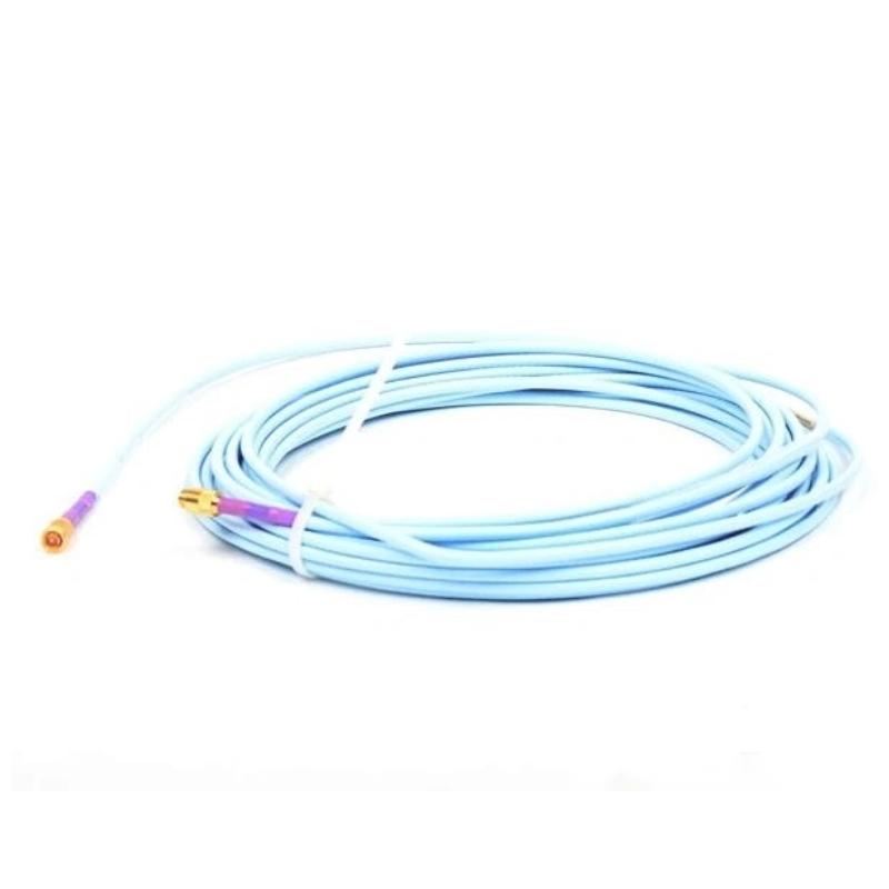
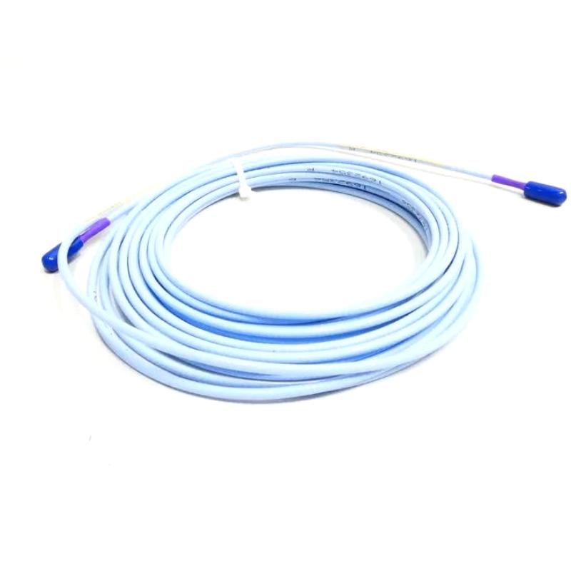
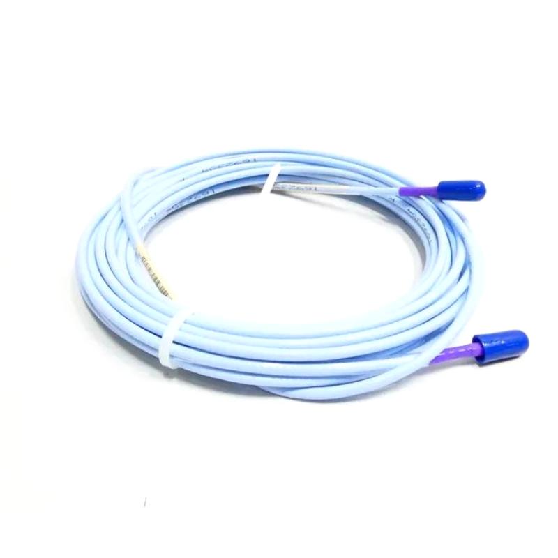
- Bently Nevada
- 330730-080-00-05
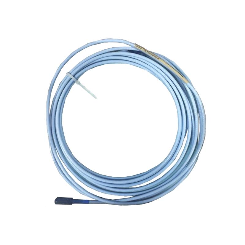
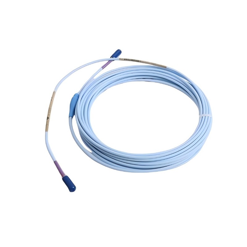
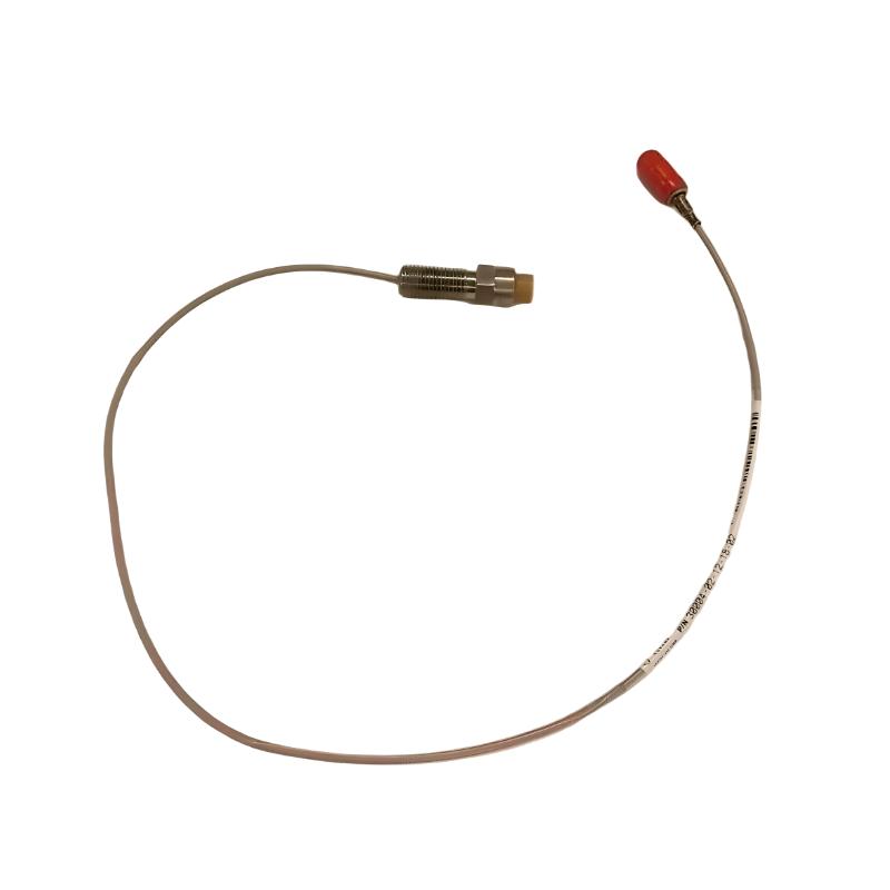
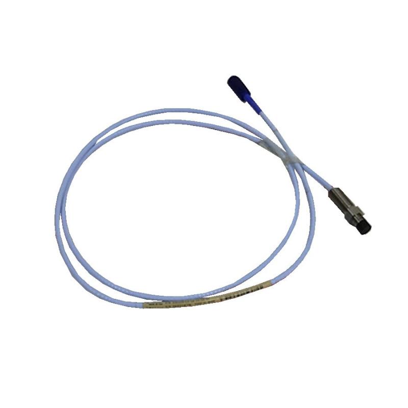
- 3300 XL 11mm Extension Cable
- USA
- 4.0 m
- 1kg
- Xiamen, China
- New & In Stock
- T/T, PayPal, Western Union
- 1 Year
- 1-3 Working Days
- DHL, UPS, TNT, FedEx and EMS.
- 24-Hour Service
- COO
- 3
Our advantage

Global Logistics
We have a 10-year logistics and express cooperation agreement, so our products can be shipped to any place in the world.

Brand new and original
Our products are imported in bulk from the place of origin. Because of the cooperative relationship, our products are all original and 100% new.

24-hour service
We provide 7*24 hours service to our customers. We will be there whenever you need us.

Price advantage
All our products are priced very favorably because we have our own warehouse and supply.
| Company Information | |||
| [email protected] | |||
| Mobile | +8615980777398 | ||
| +8615980777398 | |||
| 15980777398 |
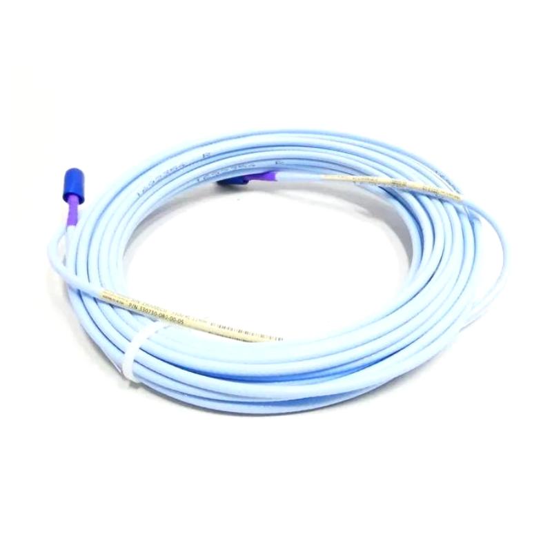
Bently Nevada 330730-080-00-05 Extension Cable: Technical Specifications, Product Description, Applications, Advantages, and Related Models
1. Product Overview
The Bently Nevada 330730-080-00-05 is a model designation associated with the 330730 extension cable product family used in industrial proximity measurement systems. Extension cables serve as an important connection between a compatible proximity probe and its associated proximitor sensor, allowing the sensing element and signal-conditioning equipment to be installed at suitable locations within a machine installation.
In rotating machinery monitoring, the extension cable forms part of the complete measurement circuit. The probe detects changes in the distance between its sensing tip and a conductive target, such as a rotating shaft. The cable carries the corresponding electrical signal to the compatible sensor electronics, where it can be processed for machinery monitoring.
The cable itself does not independently measure vibration or determine machine condition. Its role is to provide the correct electrical and mechanical connection within the overall measurement system.
Important specification note: The complete technical specification for the exact order code 330730-080-00-05 has not been independently verified. Consequently, exact cable length, connector configuration, dimensions, weight, and the meaning of the final ordering-code suffix should be confirmed before purchasing or installing the product. The description below distinguishes general product-family characteristics from values that remain unconfirmed.
2. Technical Parameters
The following table provides a structured overview of the model and its intended function.
| Parameter | Specification |
|---|---|
| Brand | Bently Nevada |
| Model | 330730-080-00-05 |
| Product type | Extension cable assembly |
| Product series | 3300 XL proximity measurement system |
| Related equipment | Compatible proximity probe and proximitor sensor |
| Primary function | Electrical connection between compatible sensing components |
| Measurement system | Non-contact proximity measurement |
| Typical measurement applications | Shaft vibration and relative shaft displacement monitoring |
| Cable length | Requires confirmation for this exact order code |
| Connector configuration | Requires confirmation |
| Cable construction | Requires confirmation against the supplied assembly |
| Electrical impedance | Requires confirmation |
| Capacitance | Requires confirmation |
| Conductor configuration | Requires confirmation |
| Shielding arrangement | Requires confirmation |
| Operating temperature | Refer to the specification for the exact cable configuration |
| Installation type | Industrial machinery sensor installation |
| Mounting method | Routed and secured between compatible components |
| Environmental suitability | Must be evaluated against the installation environment |
| Overall dimensions | Not independently confirmed |
| Net weight (kg) | Not independently confirmed |
| Gross weight (kg) | Depends on packaging and included accessories |
| Replacement compatibility | Must be checked against the complete installed system |
2.1 Dimensions and Weight
Physical dimensions and weight are important when planning equipment installation, replacement, transportation, and spare-parts inventory.
For an extension cable assembly, the overall length is normally the most significant physical measurement. Connector size, cable diameter, protective hardware, and packaging may also affect the dimensions recorded for the product.
| Physical parameter | Value for 330730-080-00-05 |
|---|---|
| Overall cable length | Requires confirmation |
| Cable outside diameter | Requires confirmation |
| Connector length | Requires confirmation |
| Connector diameter | Requires confirmation |
| Protective hardware dimensions | Requires confirmation |
| Minimum bend radius | Refer to the applicable cable specification |
| Net weight (kg) | Not verified |
| Gross shipping weight (kg) | Not verified |
| Packaging dimensions | Depends on the supplied package |
An exact weight should not be estimated from the model number alone. Net weight refers to the cable assembly itself, while gross weight includes packaging and any accessories supplied with the item.
For purchasing records, warehouse management, and freight calculations, the actual supplier specification or a measured sample should be used.
2.2 Electrical Parameters and Compatibility
Extension cables used in proximity measurement systems must meet the electrical requirements of the probe and associated sensor electronics.
The following parameters should be checked when identifying a replacement:
| Electrical parameter | Description | Verification requirement |
|---|---|---|
| Impedance | Characteristic electrical impedance of the cable | Confirm against the intended system |
| Capacitance | Electrical capacitance per unit length or assembly | Confirm against the product specification |
| Conductor resistance | Resistance of the cable conductor | Confirm if specified for the assembly |
| Insulation resistance | Electrical isolation between conductors and other conductive elements | Refer to applicable test requirements |
| Shielding | Arrangement used to control electrical interference | Confirm the cable construction |
| Connector interface | Electrical and mechanical connection at each end | Match the existing equipment |
| Total system length | Combined length of the probe, extension cable, and related components as applicable | Confirm compatibility with the proximitor |
| Environmental rating | Permitted operating conditions | Confirm for the installation location |
These parameters should be evaluated together rather than individually. A cable that physically fits the existing connectors may still be electrically unsuitable for the measurement system.
3. Detailed Product Description
3.1 General Function
The 330730-080-00-05 is described as an extension cable model associated with industrial proximity sensing equipment. Its intended role is to provide a connection between a compatible probe and its corresponding sensor electronics.
In a typical installation, the probe is mounted close to the shaft or target being monitored. The proximitor sensor is positioned where it can be installed, connected, inspected, and maintained conveniently. An extension cable provides the required connection between these components.
This arrangement is particularly useful when mechanical restrictions prevent the probe and sensor electronics from being installed immediately beside one another.
3.2 Role in Shaft Vibration Monitoring
Proximity probes are commonly used to monitor the position of a rotating shaft relative to the probe mounting point.
As the shaft moves, the gap between the shaft surface and the probe tip changes. A compatible proximity measurement system converts these changes into an electrical signal that can be used by monitoring equipment.
The extension cable carries the signal between the sensing component and the associated electronics. Its electrical characteristics and length therefore need to match the intended system configuration.
A correctly selected cable helps preserve the designed measurement arrangement. An incompatible cable, damaged connector, or poor installation can contribute to unreliable readings.
3.3 Cable and Connector Considerations
The precise construction of the 330730-080-00-05 should be confirmed for the supplied unit. In general, industrial extension cables used in sensor systems must meet several functional requirements.
Electrical insulation: The insulation must provide suitable separation between electrical elements and help maintain stable performance under the specified operating conditions.
Signal integrity: The cable must be appropriate for the electrical characteristics of the sensor circuit. Incorrect cable properties can affect the behavior of the complete measurement system.
Connector reliability: Connectors must provide a secure electrical interface and remain mechanically stable during normal operation.
Mechanical protection: Appropriate routing and securing help prevent damage caused by abrasion, excessive bending, crushing, or tension.
Environmental suitability: The cable assembly must be appropriate for the temperature, moisture, oil exposure, vibration, and other conditions present at the installation site.
These characteristics should be checked against the exact cable specification rather than assumed from the general product family.
4. Product Applications
4.1 Steam and Gas Turbines
Turbines operate at high rotational speeds and may be critical to the continuous operation of a power generation or industrial facility.
Proximity measurement systems can be used to monitor shaft vibration and relative shaft displacement. A compatible extension cable connects the probe to the sensor electronics, allowing the measurement system to be installed according to the turbine’s mechanical layout.
The resulting measurements can support condition monitoring and maintenance investigations.
4.2 Centrifugal Compressors
Compressors are widely used in industrial processes, gas handling, refrigeration, and other applications requiring continuous mechanical operation.
Shaft monitoring systems can provide information about changes in shaft movement and vibration-related behavior. The extension cable forms part of the connection between the probe and sensor electronics.
During installation, the cable should be routed away from sharp edges, hot surfaces beyond its permitted rating, and components that could damage or pull on the assembly.
4.3 Industrial Pumps
Large pumps may operate continuously in water treatment, energy production, chemical processing, and general industrial services.
Where a compatible proximity measurement system is installed, an extension cable connects the sensing element to the associated electronics. The condition of the cable and its connectors can influence the reliability of the resulting measurement signal.
Regular inspection is useful in installations exposed to moisture, oil, vibration, or restricted maintenance access.
4.4 Gearboxes and Rotating Drives
Gearboxes, coupled drives, and other rotating equipment may use shaft monitoring systems to observe mechanical movement.
A suitable extension cable allows the probe and sensor electronics to be positioned according to the physical arrangement of the machinery.
The cable does not independently identify gear wear, bearing damage, or alignment problems. Instead, it supports the measurement system that supplies information for further analysis.
4.5 Power Generation Equipment
Power generation facilities use monitoring systems to evaluate the condition of critical rotating assets.
Extension cables can form part of proximity measurement installations associated with turbines and other suitable rotating machinery. Maintaining correct cable compatibility helps the system deliver the intended measurement signals to the monitoring equipment.
4.6 Petrochemical and Process Plants
Process plants frequently contain compressors, pumps, turbines, and other machines whose unexpected shutdowns may affect production.
A correctly configured proximity measurement system can provide information about shaft movement and vibration-related conditions. The extension cable contributes to the reliable connection of the system components.
The suitability of any cable for a hazardous area must be assessed according to the requirements of the actual installation and the applicable equipment specifications.
4.7 Predictive Maintenance Programs
Predictive maintenance uses operating measurements and historical information to identify changes in machinery condition.
Proximity monitoring data can help maintenance personnel determine when additional inspection or diagnostic work may be appropriate.
The extension cable supports this process by providing the intended connection between the sensing element and its electronics. It is one component of a larger measurement chain that must be maintained as a complete system.
5. Product Advantages
5.1 Supports Flexible Component Placement
The extension cable allows the probe and associated sensor electronics to be located at practical positions within the machine installation.
This flexibility is valuable where access is limited or where the machinery layout makes direct connection impractical.
5.2 Helps Maintain the Intended Signal Path
A correctly matched extension cable provides the electrical connection required by the measurement system.
Maintaining the intended cable configuration helps preserve the system’s designed operating characteristics.
5.3 Facilitates Replacement and Maintenance
If an extension cable becomes damaged, replacing the compatible cable may allow the existing probe and sensor electronics to remain in service, provided they are otherwise functioning correctly.
This can simplify maintenance compared with replacing a larger assembly unnecessarily.
The replacement must still be checked for correct electrical characteristics, cable length, connectors, and system compatibility.
5.4 Supports Reliable Industrial Monitoring
A suitable cable and properly maintained connectors help reduce connection-related problems.
Reliability depends on the entire installation, including the probe, proximitor, cable routing, connector condition, and monitoring equipment. No cable can compensate for an incompatible system or a damaged sensing component.
5.5 Provides Installation Flexibility
Cable routing can be adapted to the physical layout of the machinery, subject to the permitted cable length and installation requirements.
Correct routing helps protect the assembly from abrasion, excessive bending, tension, and interference with moving components.
5.6 Simplifies Spare-Parts Identification
Keeping the complete model number in the maintenance database helps distinguish this cable from related configurations.
A clear record of the installed cable can reduce identification errors during planned maintenance and emergency repairs.
5.7 Supports Condition Monitoring Infrastructure
The extension cable is part of the infrastructure that allows a proximity measurement system to operate as intended.
Although it does not generate diagnostic conclusions, it supports the collection of measurements used by machinery monitoring and maintenance personnel.
6. Brand Information
The product is associated with Bently Nevada, a brand known for industrial machinery condition monitoring and protection equipment.
Its product range includes technologies used to monitor rotating machinery, including proximity measurement systems and vibration monitoring equipment.
In these applications, sensors and related electronics help collect information about machine behavior. The measurements may be used by monitoring systems and maintenance teams to assess operating conditions and investigate changes over time.
The 3300 XL family is associated with non-contact proximity measurement. Within this type of system, the probe, extension cable, and proximitor must be configured to operate together.
For the 330730-080-00-05, the brand and product-family identification provide a starting point for identifying the intended application. The complete model specification remains necessary for selecting a replacement.
7. Product Series: 3300 XL Proximity Measurement System
The 3300 XL product family is associated with industrial proximity sensing and measurement applications.
Depending on the configuration, a complete system can include a proximity probe, extension cable, proximitor sensor, and monitoring equipment.
7.1 Series Characteristics
| Parameter | Description |
|---|---|
| Product family | 3300 XL |
| Primary technology | Non-contact proximity measurement |
| Typical target | Conductive shaft or target surface |
| Main measurement purpose | Shaft vibration and relative displacement monitoring |
| Typical components | Probe, extension cable, proximitor sensor, monitoring equipment |
| Common applications | Turbines, compressors, pumps, and other rotating machinery |
| System selection | Must account for electrical and mechanical compatibility |
| Installation considerations | Cable routing, connector security, mounting, and environmental conditions |
| Maintenance considerations | Cable condition, connector integrity, and measurement signal quality |
7.2 Why Correct System Matching Matters
A proximity measurement system depends on the combined properties of its components.
The cable length and electrical characteristics may influence the behavior of the complete circuit. As a result, selecting an extension cable based only on appearance, connector fit, or a similar model prefix is not sufficient.
When replacing the 330730-080-00-05, confirm the existing probe model, proximitor model, cable identification, and required total system configuration.
8. Installation and Maintenance Guidelines
8.1 Before Installation
– Confirm that the full model number matches the required replacement.
– Check the cable’s intended probe and proximitor compatibility.
– Inspect the connectors for damage, contamination, and corrosion.
– Confirm the cable length and connector arrangement.
– Check that the operating environment falls within the permitted conditions for the actual assembly.
8.2 During Installation
– Route the cable away from sharp edges and moving machinery.
– Avoid excessive pulling force, twisting, crushing, and bending.
– Observe the applicable minimum bend radius.
– Secure the cable without putting unnecessary tension on the connectors.
– Follow the equipment-specific requirements for shielding, grounding, and electrical separation.
8.3 During Routine Maintenance
– Inspect the cable jacket for cuts, abrasion, deformation, and other damage.
– Check that the connectors remain secure.
– Investigate intermittent measurements and unexpected signal changes systematically.
– Replace damaged cables with a verified compatible assembly.
– Record the model number and replacement date in the equipment maintenance history.
9. Five Related Models or Series Alternatives
The following models are related candidates for further comparison. Their inclusion does not establish that they are direct replacements for the 330730-080-00-05.
| No. | Model | Product category | Key parameters and selection considerations | Dimensions | Weight (kg) |
|---|---|---|---|---|---|
| 1 | 330730-040-00-00 | Extension cable family candidate | Confirm cable length, connector arrangement, and electrical compatibility | Not verified | Not verified |
| 2 | 330730-040-03-00 | Extension cable family candidate | Compare the complete ordering code and required system configuration | Not verified | Not verified |
| 3 | 330730-040-03-05 | Extension cable family candidate | Verify cable construction, connector configuration, and application requirements | Not verified | Not verified |
| 4 | 330730-040-10-05 | Extension cable family candidate | Confirm the exact assembly and compatibility with the installed sensor system | Not verified | Not verified |
| 5 | 330730-040-12-00 | Extension cable family candidate | Check the complete model specification before considering replacement | Not verified | Not verified |
Selection Advice
The appropriate replacement is determined by the installed system, not simply by which model appears most similar.
Before purchasing any of these candidates, confirm:
– The complete model number and suffixes.
– The required cable length.
– The electrical characteristics of the cable.
– The connector interfaces at both ends.
– Compatibility with the installed proximity probe and proximitor.
– The physical dimensions and net weight required for inventory or installation planning.
10. Five Other Models and Product Categories from the Same Brand
The following table provides additional models or product categories associated with the brand’s machinery monitoring range. These are not all extension cables and should not be treated as direct substitutes for the target model.
The exact part numbers and specifications must be checked against the intended application before ordering.
| No. | Model | Product category | Main parameters and identifying considerations | Dimensions | Weight (kg) |
|---|---|---|---|---|---|
| 1 | 330101-00-08-10-02-00 | Proximity probe candidate | Verify probe dimensions, mounting configuration, and sensor compatibility | Requires confirmation | Not verified |
| 2 | 330103-00-07-10-02-00 | Proximity probe candidate | Confirm probe configuration, connection type, and intended measurement system | Requires confirmation | Not verified |
| 3 | 330104-00-06-10-02-00 | Proximity probe candidate | Check the exact part number and applicable installation requirements | Requires confirmation | Not verified |
| 4 | 330180-50-00 | Proximitor sensor candidate | Verify sensor configuration and compatibility with the complete probe system | Requires confirmation | Not verified |
| 5 | 3300 XL 11 mm proximity probe system | Proximity measurement system | System-level configuration using compatible probe, cable, and sensor components | Depends on selected components | Depends on selected components |
These recommendations are intended to help organize a comparison of related product categories. The model designations above should be validated before use in a formal quotation or purchasing specification.
11. Procurement and Replacement Checklist
The following checklist can be used when preparing a purchase request for the 330730-080-00-05.
| Item to verify | Required information | Purpose |
|---|---|---|
| Product identification | Full model number from the cable label | Avoids confusion between similar models |
| Cable length | Confirmed overall cable length | Ensures the cable suits the installation |
| Connector configuration | Type and interface at each end | Ensures correct physical connection |
| Probe model | Exact installed probe model | Confirms compatibility |
| Proximitor model | Exact installed sensor model | Confirms compatibility |
| Electrical properties | Applicable impedance and capacitance specifications | Supports correct system operation |
| Environmental rating | Permitted operating conditions | Helps ensure suitability for the installation |
| Physical dimensions | Cable diameter and connector dimensions | Supports installation planning |
| Net weight (kg) | Weight of the cable assembly | Supports inventory and shipping calculations |
| Gross weight (kg) | Weight including packaging | Supports freight planning |
| Replacement approval | Confirmation against the installed system | Reduces the risk of incorrect substitution |
12. Conclusion
The Bently Nevada 330730-080-00-05 is treated in this product description as an extension cable model associated with the 3300 XL proximity measurement product family. Its general purpose is to provide the electrical connection between a compatible proximity probe and the associated sensor electronics.
Its importance comes from its role in the complete measurement chain. Correct cable selection, appropriate routing, secure connectors, and compatibility with the installed probe and proximitor all contribute to reliable machinery monitoring.
The exact cable length, electrical specifications, connector configuration, physical dimensions, and weight in kilograms have not been confirmed for this particular model. These details should be verified from the actual product identification and applicable technical specification before the information is used for procurement, installation, or inventory control.
The related models listed above provide a starting point for product comparison, but they are not guaranteed equivalents. The final selection should always be based on the confirmed requirements of the installed proximity measurement system.