

ProductPRODUCT
Featured products


Contact Us
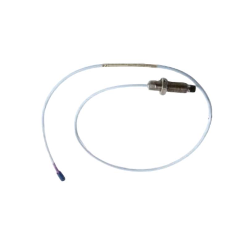
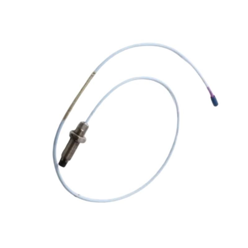
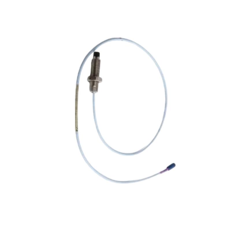
- Bently Nevada
- 330704-000-060-50-02-00
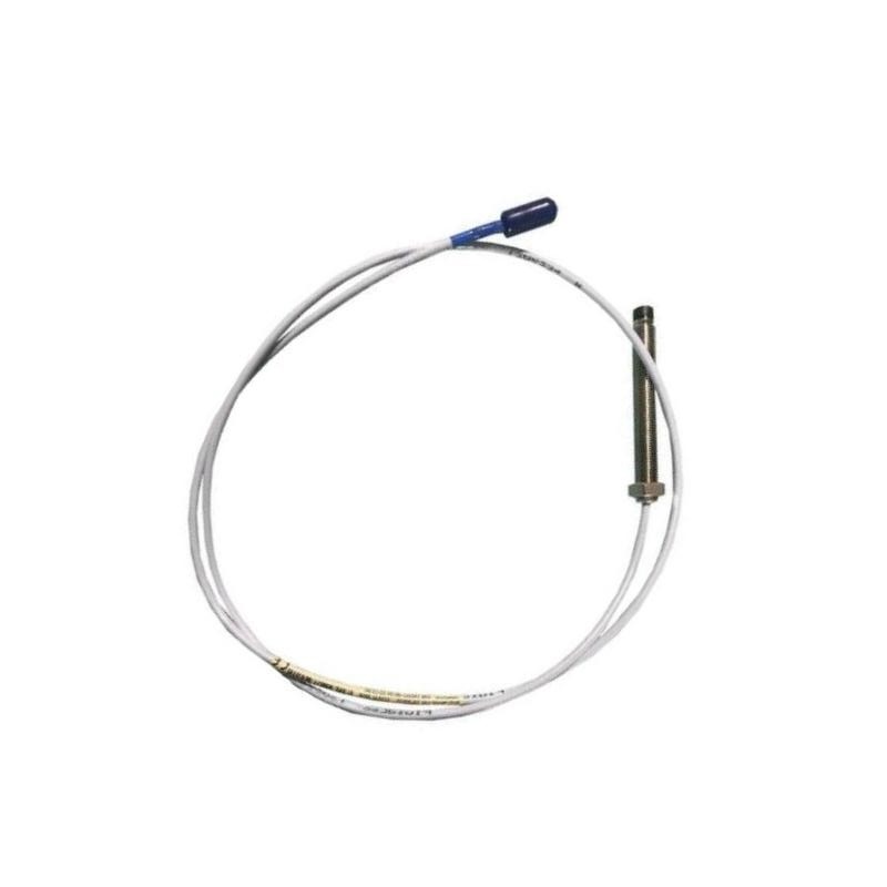
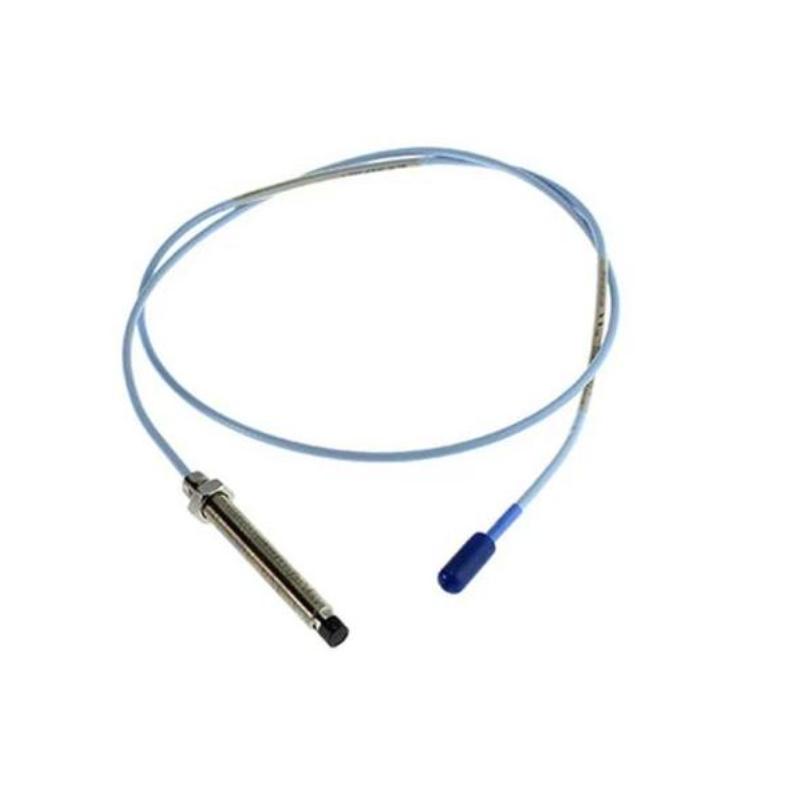
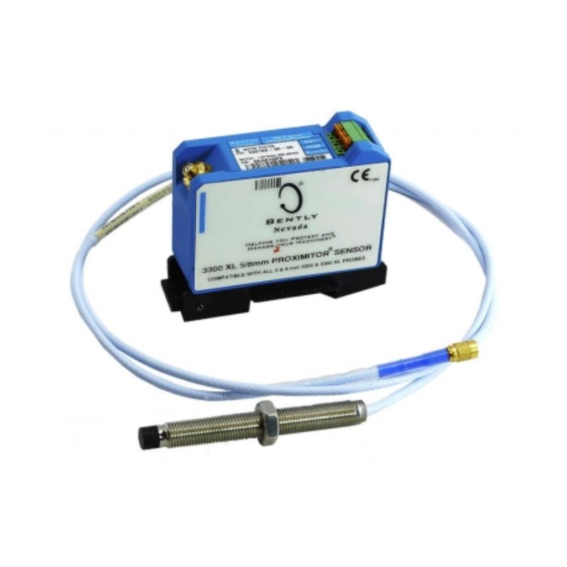
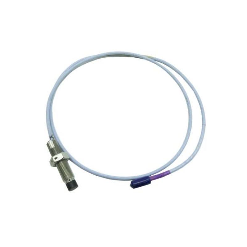
- 3300 XL 11 mm Proximity Probe
- USA
- 50 mm
- 2kg
- Xiamen, China
- New & In Stock
- T/T, PayPal, Western Union
- 1 Year
- 1-3 Working Days
- DHL, UPS, TNT, FedEx and EMS.
- 24-Hour Service
- COO
- 4
Our advantage

Global Logistics
We have a 10-year logistics and express cooperation agreement, so our products can be shipped to any place in the world.

Brand new and original
Our products are imported in bulk from the place of origin. Because of the cooperative relationship, our products are all original and 100% new.

24-hour service
We provide 7*24 hours service to our customers. We will be there whenever you need us.

Price advantage
All our products are priced very favorably because we have our own warehouse and supply.
| Company Information | |||
| [email protected] | |||
| Mobile | +8615980777398 | ||
| +8615980777398 | |||
| 15980777398 |
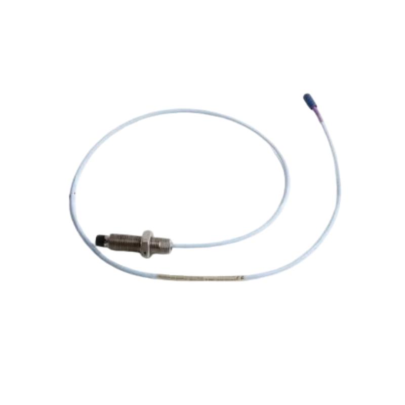
Bently Nevada 330704-000-060-50-02-00 Proximity Probe
1. Product Overview
The Bently Nevada 330704-000-060-50-02-00 is an industrial instrumentation model intended for evaluation in proximity-probe applications. Proximity probes are used in rotating machinery monitoring systems to measure the distance between a sensor tip and a conductive target, commonly a rotating shaft. When paired with compatible monitoring electronics, the measurement signal can be used to assess shaft displacement, relative vibration, and changes in shaft position during equipment operation.
In industrial facilities, rotating machinery often operates continuously under changing loads, speeds, temperatures, and process conditions. Turbines, compressors, pumps, and other critical machines can experience changes in shaft movement as operating conditions vary or mechanical components deteriorate. A correctly selected proximity probe provides a non-contact measurement signal that can help maintenance personnel monitor operating trends and investigate abnormal mechanical behavior.
The complete model number is important when selecting this type of instrument. Differences in the ordering code may represent changes in probe construction, mounting dimensions, cable arrangement, connector configuration, or other options. The exact configuration of 330704-000-060-50-02-00 should therefore be confirmed before it is purchased as a direct replacement for an existing sensor.
2. Brand and Product Series
| Parameter | Description |
|---|---|
| Brand | Bently Nevada |
| Model | 330704-000-060-50-02-00 |
| Product category | Industrial proximity probe; exact configuration to be verified |
| Product series | Requires confirmation against the complete part-number record |
| Measurement technology | Proximity measurement; exact sensing principle requires confirmation |
| Primary function | Non-contact measurement of target displacement, if confirmed for this configuration |
| Typical target | Conductive metallic shaft or target surface |
| Typical system components | Probe, compatible cable, driver, and monitoring electronics |
| Main application | Rotating machinery monitoring |
| Installation method | Fixed mounting near the target surface |
| Cable configuration | Requires confirmation |
| Connector configuration | Requires confirmation |
| Electrical compatibility | Must be checked against the complete measurement system |
| Overall dimensions | Not confirmed |
| Net weight | Not confirmed (kg) |
| Shipping weight | Not confirmed (kg) |
The 3300 XL family is associated with industrial proximity-probe technology, but the exact series designation for this complete model number should not be assumed without configuration-specific confirmation.
3. Detailed Product Parameters
The following table summarizes the main technical and physical parameters relevant to product identification, installation, and procurement. Values that cannot be established reliably from the model number alone are marked as unconfirmed rather than estimated.
| Parameter | Specification |
|---|---|
| Model | 330704-000-060-50-02-00 |
| Brand | Bently Nevada |
| Product type | Industrial proximity probe; exact configuration to be verified |
| Product series | Requires confirmation |
| Measurement principle | Requires confirmation for this exact model |
| Measurement mode | Depends on the confirmed sensor configuration |
| Typical measurement object | Conductive shaft or metallic target |
| Typical measurement purpose | Relative shaft displacement and vibration monitoring |
| Probe tip diameter | Not confirmed |
| Mounting thread diameter | Not confirmed |
| Thread pitch | Not confirmed |
| Threaded section length | Not confirmed |
| Unthreaded section length | Not confirmed |
| Probe case length | Not confirmed |
| Cable length | Not confirmed |
| Connector type | Not confirmed |
| System sensitivity | Not confirmed |
| Linear measurement range | Not confirmed |
| Operating temperature range | Requires the applicable technical specification |
| Environmental protection rating | Not confirmed |
| Overall length | Not confirmed |
| Maximum body diameter | Not confirmed |
| Compatible electronics | Must be matched to the verified probe configuration |
| Net weight | Not confirmed (kg) |
| Packaging dimensions | Not confirmed |
| Shipping weight | Not confirmed (kg) |
| Maintenance requirements | Periodic inspection of mounting, cable, connectors, and signal condition |
Dimensions and Weight
The exact dimensions and mass of 330704-000-060-50-02-00 cannot be stated reliably without a matching technical drawing or verified product record. Assigning numerical values based on a similar part number could result in incorrect installation clearances, replacement decisions, or shipping calculations.
| Physical parameter | Value |
|---|---|
| Model | 330704-000-060-50-02-00 |
| Probe tip diameter | Not confirmed |
| Thread diameter | Not confirmed |
| Thread pitch | Not confirmed |
| Threaded length | Not confirmed |
| Unthreaded length | Not confirmed |
| Probe case length | Not confirmed |
| Cable length | Not confirmed |
| Connector dimensions | Not confirmed |
| Total assembly length | Not confirmed |
| Net weight | Not confirmed (kg) |
| Shipping weight | Not confirmed (kg) |
For replacement work, the mounting thread, case length, total assembly length, and available installation clearance should be compared with the existing installation. Cable length and connector configuration must also be checked.
4. Product Description and Working Principle
A proximity probe measures the distance between its sensing tip and a target without requiring direct contact. In an eddy-current system, compatible electronics energize a sensing coil inside the probe, creating an electromagnetic field around the sensing tip.
When a conductive target enters this field, eddy currents are induced in the target material. Changes in the distance between the probe and the target alter the electromagnetic interaction. Compatible electronics convert this response into an electrical signal representing the target’s relative position within the system’s calibrated range.
When the target is a rotating shaft, the signal can reveal changes in shaft position as the machine rotates or vibrates. A monitoring system can use this information to evaluate operating behavior, compare current readings with baseline values, and support alarm functions when configured limits are exceeded.
The probe is only one part of the measurement system. Reliable readings depend on the correct probe configuration, compatible cable and driver, proper mounting, appropriate gap adjustment, and suitable monitoring-system settings.
5. Main Product Applications
5.1 Turbine Shaft Monitoring
Turbines often require continuous monitoring because shaft vibration and relative position can affect mechanical stability and equipment reliability. A suitable proximity probe can provide measurement data to a monitoring system that tracks shaft behavior during startup, normal operation, load changes, and shutdown.
Historical trends may help maintenance personnel investigate changes associated with imbalance, misalignment, bearing deterioration, or other mechanical conditions. The probe provides measurement data rather than an automatic diagnosis; identifying the cause of a change requires analysis of the complete operating information.
5.2 Compressor Monitoring
Industrial compressors operate under demanding mechanical conditions, often for extended periods. Changes in shaft vibration and relative position can provide useful information about the condition of the rotating assembly.
When the sensor is correctly selected and integrated, its signal can contribute to continuous monitoring, alarm management, and maintenance planning. The suitability of this particular model for a compressor installation must be checked against the machine’s instrumentation requirements.
5.3 Pump Monitoring
In suitable pump installations, shaft displacement measurements can help assess changes in operating behavior. Abnormal movement may be associated with misalignment, imbalance, mechanical looseness, bearing wear, or changing operating conditions.
Not every pump requires a proximity probe. The appropriate sensor type depends on the pump design, shaft and bearing arrangement, rotational speed, installation space, and monitoring objectives.
5.4 Rotating Machinery Protection
When connected to compatible monitoring electronics, a proximity probe can supply a measurement signal used by a machinery protection system. The monitor evaluates the signal against configured alarm or trip limits and can alert operators when measured conditions fall outside the defined operating range.
Alarm and trip settings should be established according to the machine design and operational requirements. They should not be selected solely from the sensor model number.
5.5 Industrial Condition Monitoring
Proximity measurement can also be used on other rotating machines where shaft-relative displacement measurements are required. Application suitability depends on the target material, mounting arrangement, operating environment, cable routing, and compatibility with the installed monitoring equipment.
6. Product Advantages
Non-Contact Measurement
The sensing method does not require the probe to touch the rotating shaft. This makes proximity measurement suitable for many high-speed rotating applications where continuous contact would be impractical.
Continuous Measurement Capability
When installed in a compatible system, the probe can provide ongoing measurement data. Monitoring equipment can use these readings to track changes in shaft behavior rather than relying only on periodic manual inspections.
Support for Condition-Based Maintenance
Changes in shaft displacement and vibration trends can help maintenance teams determine when additional investigation may be necessary. This can support maintenance planning when measurements are evaluated alongside operating conditions and established baseline data.
Integration with Monitoring Systems
A properly selected probe can form part of a wider machinery-monitoring arrangement. The probe, extension cable, driver, and monitor must be compatible with one another; matching the brand alone is not enough to guarantee compatibility.
No Routine Sliding Contact at the Sensing Point
Because the probe normally measures without touching the target, the sensing method does not depend on a sliding contact surface. The probe mounting, cable, and connectors still need regular inspection to maintain reliable operation.
Support for Historical Trend Analysis
When measurements are collected consistently, engineers can compare current readings with historical data. This helps identify persistent changes that may warrant further mechanical inspection or instrumentation troubleshooting.
7. Installation and Commissioning
Before installation, check the complete model number against the equipment documentation. Confirm the mounting thread, body dimensions, cable length, connector arrangement, and compatibility with the existing monitoring electronics.
The probe should be installed on a mechanically stable mounting point. Movement of the bracket or probe body can introduce unwanted changes into the measurement and may be mistaken for actual shaft displacement.
Set the probe gap according to the instructions for the verified probe-and-driver system. An incorrect gap may place the measurement outside the intended operating range or cause readings that are difficult to interpret.
Cable routing should protect the cable from excessive heat, abrasion, sharp bends, vibration, and other environmental stresses. Connectors should be clean, correctly fitted, and secured according to the installation requirements.
After installation, confirm that the measurement signal is stable and plausible. Where historical readings are available, compare the new values with the established baseline and verify the monitor’s configuration.
8. Maintenance and Troubleshooting
Although proximity probes avoid direct contact with the target, the complete measurement system should still be inspected periodically.
– Unstable readings: Inspect the mounting arrangement, connector seating, cable condition, and electrical installation.
– Unexpected position readings: Verify the probe gap, mounting geometry, target condition, and monitoring-system settings.
– Signal loss: Check the probe, cable, connectors, driver, and associated monitoring equipment.
– Changes over time: Compare the readings with historical trends and operating conditions. Investigate potential mechanical movement, target changes, or instrumentation faults.
– Replacement incompatibility: Confirm the complete part number and system compatibility before installing a substitute.
Troubleshooting should consider the full measurement chain. Replacing the probe alone may not resolve a problem caused by a damaged cable, incompatible electronics, poor mounting, or an incorrect installation gap.
9. Five Related Models for Comparison
The following models are candidates for further comparison within related proximity-probe configurations. Their precise relationship to 330704-000-060-50-02-00 and their individual specifications have not been confirmed. They should not be treated as guaranteed compatible replacements.
| No. | Model | Parameters to compare | Dimensions | Net weight |
|---|---|---|---|---|
| 1 | 330704-000-050-90-02-RU | Full ordering code, mounting arrangement, cable, and connector | Not confirmed | Not confirmed (kg) |
| 2 | 330704-000-050-90-02-CN | Suffix differences and configuration requirements | Not confirmed | Not confirmed (kg) |
| 3 | 330704-000-050-90-02-05 | Mechanical and electrical configuration | Not confirmed | Not confirmed (kg) |
| 4 | 330704-000-050-10-02-CN | Cable arrangement, mounting dimensions, and system compatibility | Not confirmed | Not confirmed (kg) |
| 5 | 330703-000-050-10-02-CN | Probe construction and installation requirements | Not confirmed | Not confirmed (kg) |
These models are listed for comparison, not as verified equivalents. Before choosing one, confirm the exact product family, mounting dimensions, cable and connector configuration, electrical characteristics, and intended application.
10. Five Additional Models from the Same Brand
The following model numbers may be useful starting points when comparing other proximity-probe configurations and related machinery-monitoring products. This is a general comparison list, not a verified sales or popularity ranking. The precise product type and specifications of each model should be confirmed individually.
| No. | Model | General comparison purpose | Dimensions | Net weight |
|---|---|---|---|---|
| 1 | 330703-000-050-10-02-CN | Related probe configuration candidate | Not confirmed | Not confirmed (kg) |
| 2 | 330703-000-070-10-02-CN | Compare mounting and physical configuration | Not confirmed | Not confirmed (kg) |
| 3 | 330709-000-050-10-02-00 | Verify product type and system compatibility | Not confirmed | Not confirmed (kg) |
| 4 | 330701-00-30-10-02-CN | Compare mechanical construction and electrical requirements | Not confirmed | Not confirmed (kg) |
| 5 | 330907-05-30-10-02-CN | Confirm product family and intended monitoring application | Not confirmed | Not confirmed (kg) |
These models should not be assumed to share the same dimensions, sensitivity, cable length, connector type, weight, or compatible electronics. A model can serve a similar monitoring purpose without being mechanically or electrically interchangeable.
11. Procurement Checklist
Before purchasing 330704-000-060-50-02-00, confirm the following details.
1. Complete part number: Check every digit and suffix against the installed equipment specification.
2. Product series: Confirm the precise series designation for this configuration.
3. Mechanical dimensions: Verify the mounting thread, probe case length, total assembly length, and installation clearance.
4. Cable and connector: Confirm the required cable length and connector arrangement.
5. Electrical compatibility: Check the driver, extension cable, and monitoring electronics.
6. Operating environment: Confirm suitability for the installation’s temperature, vibration, and environmental conditions.
7. Dimensions and weight: Obtain verified physical dimensions and net weight in kilograms for engineering records, inventory, or transport.
8. Replacement suitability: Compare the proposed model with the original component and equipment documentation before installation.
12. Final Summary
The Bently Nevada 330704-000-060-50-02-00 is a model number that requires configuration-specific verification before its exact technical characteristics can be stated confidently. Proximity probes are used in suitable industrial monitoring systems to measure shaft displacement without contact and can support vibration assessment, shaft-position monitoring, and machinery protection.
The main benefits of proximity measurement include continuous monitoring capability, no routine contact wear at the sensing point, and the ability to track changes in machine behavior over time. Actual performance depends on the correct sensor configuration, compatible electronics, proper installation, calibration, and appropriate interpretation of measurement data.
The precise product series, probe dimensions, cable arrangement, connector configuration, electrical sensitivity, and weight of this specific model remain unconfirmed here. For accurate procurement and replacement decisions, the complete ordering specification should be checked. Overall dimensions and net weight in kilograms should be verified rather than estimated, and related models should not be treated as direct replacements until their mechanical and electrical compatibility has been established.